NISSAN PRIMERA 1999 Electronic Repair Manual
PRIMERA 1999
NISSAN
NISSAN
https://www.carmanualsonline.info/img/5/57377/w960_57377-0.png
NISSAN PRIMERA 1999 Electronic Repair Manual
Trending: radio, washer fluid, CD player, fuse diagram, ABS, catalytic converter, refrigerant type
Page 811 of 2267
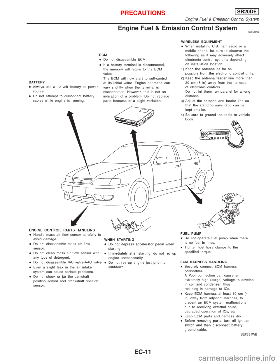
Engine Fuel & Emission Control SystemNCEC0004
SEF331WB
PRECAUTIONSSR20DE
Engine Fuel & Emission Control System
EC-11
Page 812 of 2267
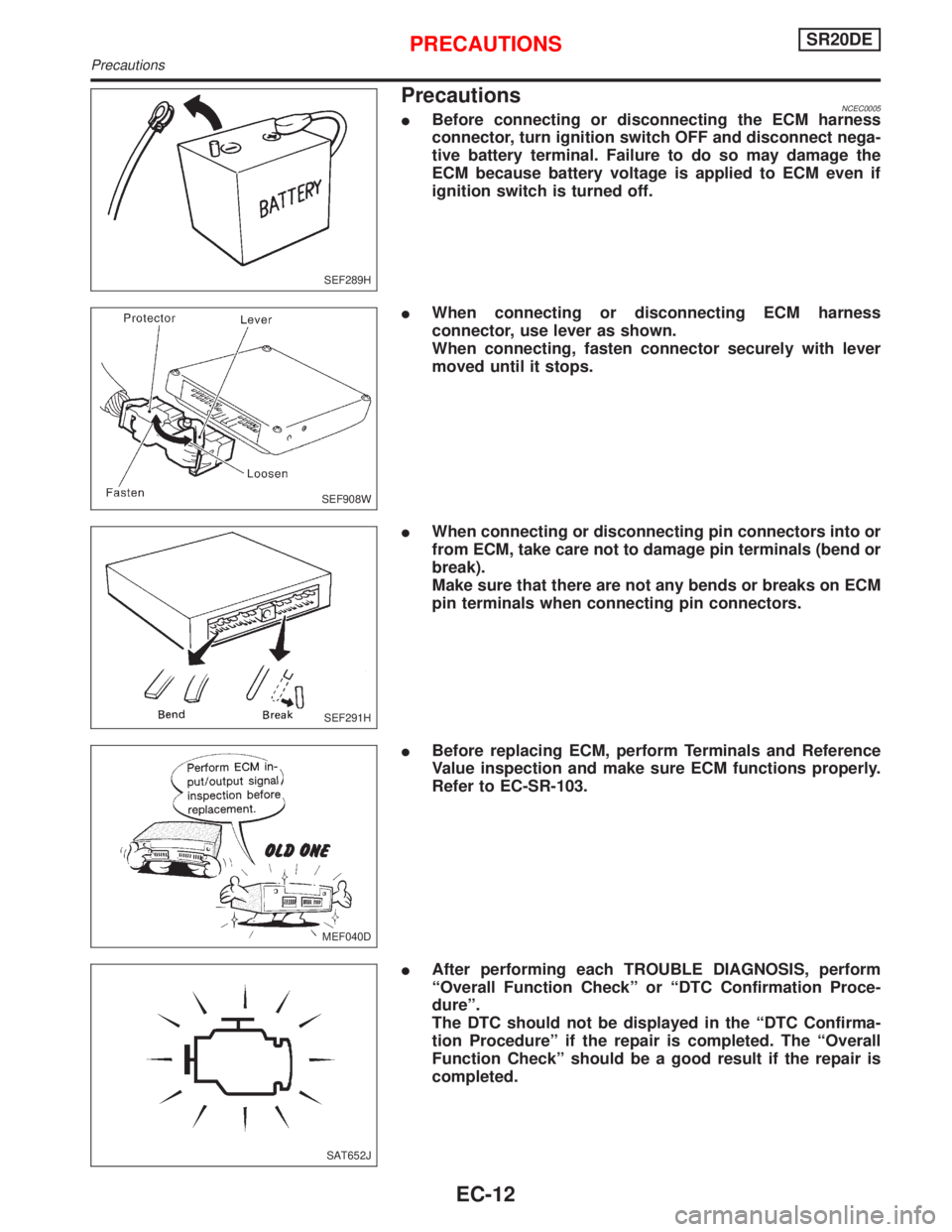
PrecautionsNCEC0005IBefore connecting or disconnecting the ECM harness
connector, turn ignition switch OFF and disconnect nega-
tive battery terminal. Failure to do so may damage the
ECM because battery voltage is applied to ECM even if
ignition switch is turned off.
IWhen connecting or disconnecting ECM harness
connector, use lever as shown.
When connecting, fasten connector securely with lever
moved until it stops.
IWhen connecting or disconnecting pin connectors into or
from ECM, take care not to damage pin terminals (bend or
break).
Make sure that there are not any bends or breaks on ECM
pin terminals when connecting pin connectors.
IBefore replacing ECM, perform Terminals and Reference
Value inspection and make sure ECM functions properly.
Refer to EC-SR-103.
IAfter performing each TROUBLE DIAGNOSIS, perform
ªOverall Function Checkº or ªDTC Confirmation Proce-
dureº.
The DTC should not be displayed in the ªDTC Confirma-
tion Procedureº if the repair is completed. The ªOverall
Function Checkº should be a good result if the repair is
completed.
SEF289H
SEF908W
SEF291H
MEF040D
SAT652J
PRECAUTIONSSR20DE
Precautions
EC-12
Page 813 of 2267
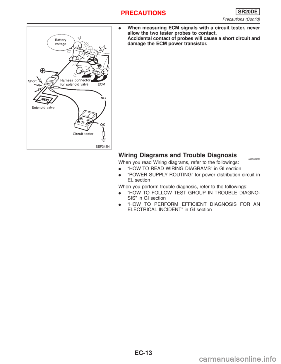
IWhen measuring ECM signals with a circuit tester, never
allow the two tester probes to contact.
Accidental contact of probes will cause a short circuit and
damage the ECM power transistor.
Wiring Diagrams and Trouble DiagnosisNCEC0006When you read Wiring diagrams, refer to the followings:
IªHOW TO READ WIRING DIAGRAMSº in GI section
IªPOWER SUPPLY ROUTINGº for power distribution circuit in
EL section
When you perform trouble diagnosis, refer to the followings:
IªHOW TO FOLLOW TEST GROUP IN TROUBLE DIAGNO-
SISº in GI section
IªHOW TO PERFORM EFFICIENT DIAGNOSIS FOR AN
ELECTRICAL INCIDENTº in GI section
SEF348N
PRECAUTIONSSR20DE
Precautions (Cont'd)
EC-13
Page 814 of 2267
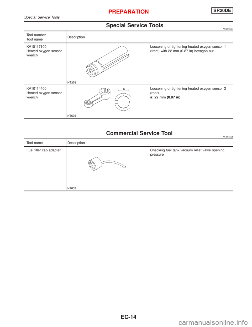
Special Service ToolsNCEC0007
Tool number
Tool nameDescription
KV10117100
Heated oxygen sensor
wrench
NT379
Loosening or tightening heated oxygen sensor 1
(front) with 22 mm (0.87 in) hexagon nut
KV10114400
Heated oxygen sensor
wrench
NT636
Loosening or tightening heated oxygen sensor 2
(rear)
a: 22 mm (0.87 in)
Commercial Service ToolNCEC0008
Tool name Description
Fuel filler cap adapter
NT653
Checking fuel tank vacuum relief valve opening
pressure
PREPARATIONSR20DE
Special Service Tools
EC-14
Page 815 of 2267
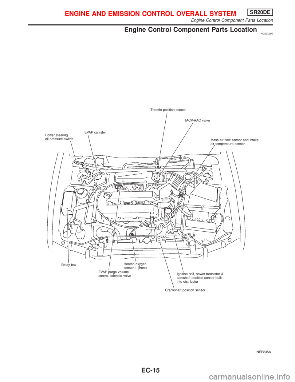
Engine Control Component Parts LocationNCEC0009
NEF235A Throttle position sensor
IACV-AAC valve
Mass air flow sensor and intake
air temperature sensor
Ignition coil, power transistor &
camshaft position sensor built
into distributor
Crankshaft position sensor Relay box
EVAP purge volume
control solenoid valveHeated oxygen
sensor 1 (front) EVAP canister
Power steering
oil pressure switch
ENGINE AND EMISSION CONTROL OVERALL SYSTEMSR20DE
Engine Control Component Parts Location
EC-15
Page 816 of 2267
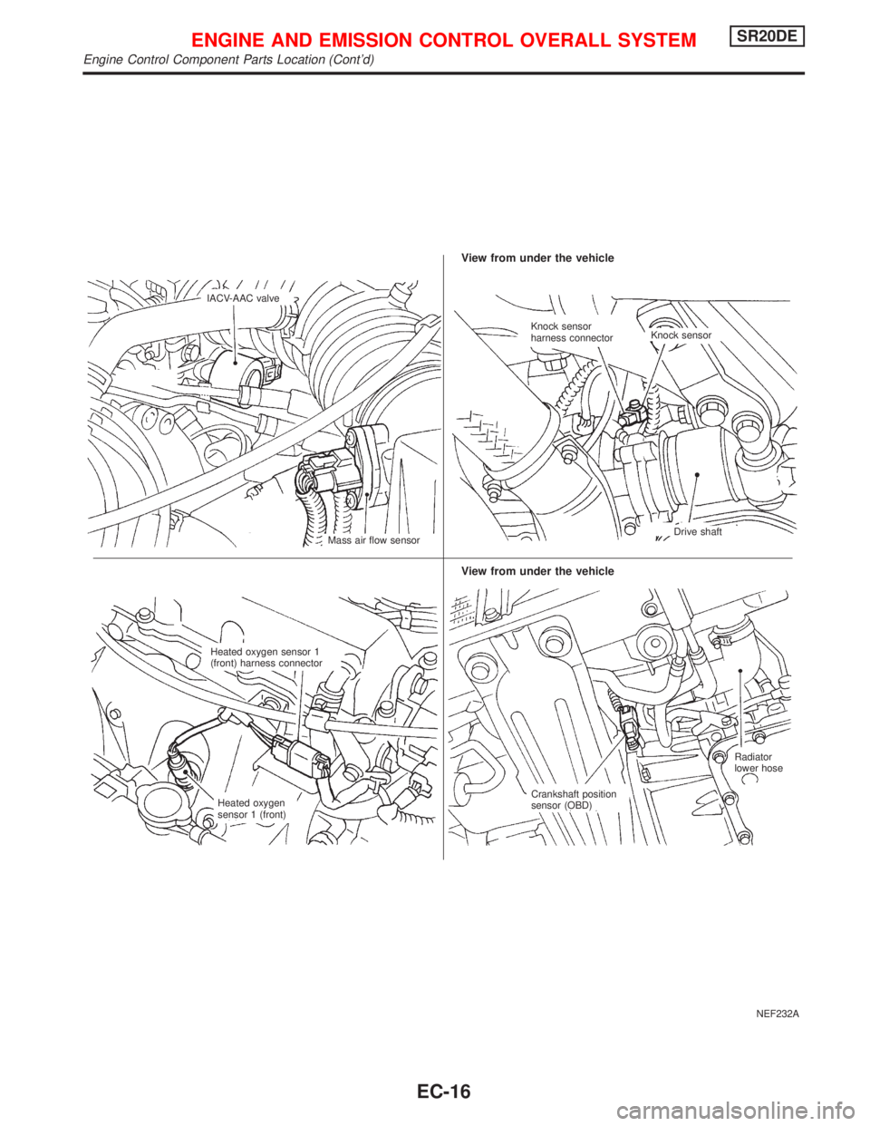
NEF232A
.IACV-AAC valve
Mass air flow sensor
View from under the vehicle
Crankshaft position
sensor (OBD)Radiator
lower hose Heated oxygen sensor 1
(front) harness connector
Heated oxygen
sensor 1 (front)
View from under the vehicle
Knock sensor
harness connectorKnock sensor
.Drive shaft
ENGINE AND EMISSION CONTROL OVERALL SYSTEMSR20DE
Engine Control Component Parts Location (Cont'd)
EC-16
Page 817 of 2267
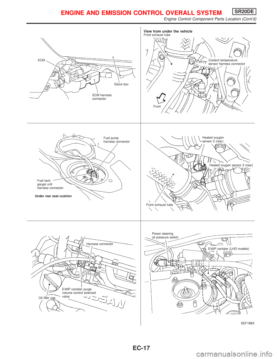
SEF188X ECM
ECM harness
connectorGlove box
View from under the vehicleFront exhaust tube
Coolant temperature
sensor harness connector
Front
Fuel pump
harness connector
Fuel tank
gauge unit
harness connector
Under rear seat cushion
Front exhaust tubeHeated oxygen
sensor 2 (rear)
Heated oxygen sensor 2 (rear)
Harness connector
EVAP canister purge
volume control solenoid
valve
Oil filler capPower steering
oil pressure switch
EVAP canister (LHD models)
ENGINE AND EMISSION CONTROL OVERALL SYSTEMSR20DE
Engine Control Component Parts Location (Cont'd)
EC-17
Page 818 of 2267
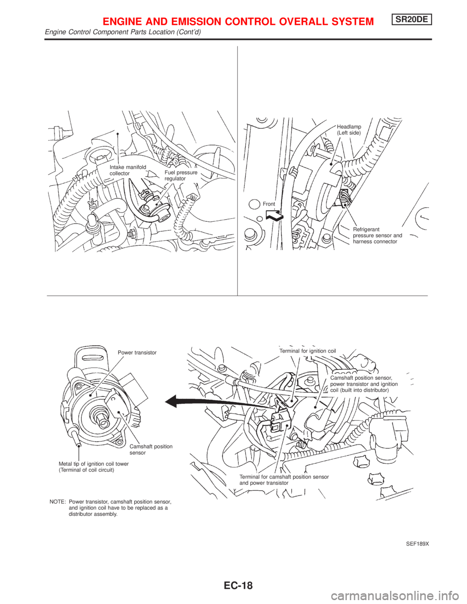
SEF189X Intake manifold
collectorFuel pressure
regulatorHeadlamp
(Left side)
Front
Refrigerant
pressure sensor and
harness connector
Power transistorTerminal for ignition coil
Camshaft position sensor,
power transistor and ignition
coil (built into distributor)
Terminal for camshaft position sensor
and power transistor Camshaft position
sensor
Metal tip of ignition coil tower
(Terminal of coil circuit)
NOTE: Power transistor, camshaft position sensor,
and ignition coil have to be replaced as a
distributor assembly.
ENGINE AND EMISSION CONTROL OVERALL SYSTEMSR20DE
Engine Control Component Parts Location (Cont'd)
EC-18
Page 819 of 2267
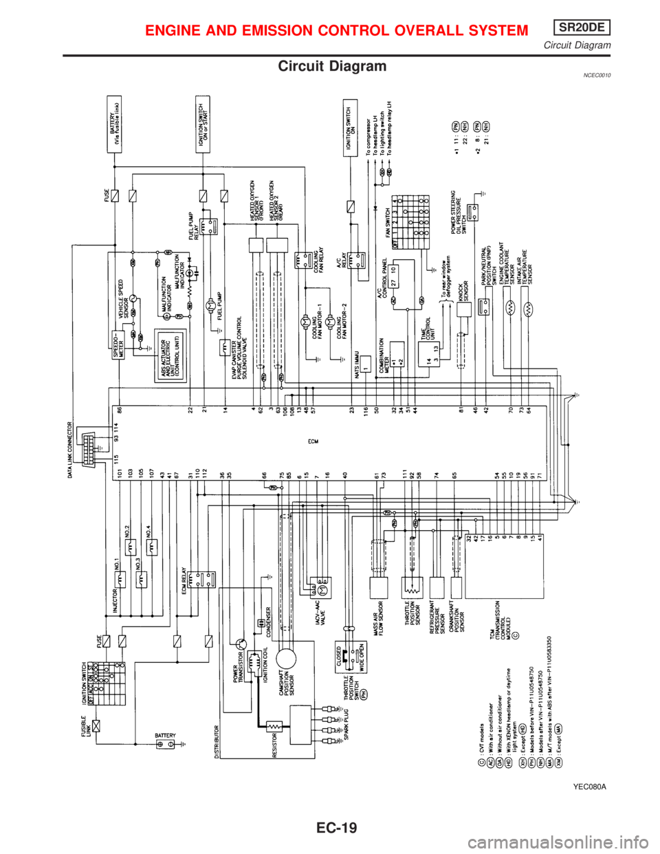
Circuit DiagramNCEC0010
YEC080A
ENGINE AND EMISSION CONTROL OVERALL SYSTEMSR20DE
Circuit Diagram
EC-19
Page 820 of 2267
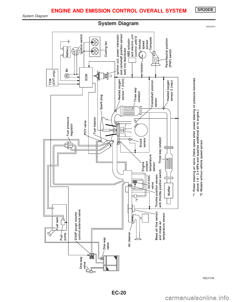
System DiagramNCEC0011
YEC117A
ENGINE AND EMISSION CONTROL OVERALL SYSTEMSR20DE
System Diagram
EC-20
Trending: engine coolant, radio antenna, wheel bolts, maintenance, service schedule, remote start, wheelbase
