alternator NISSAN PULSAR 1987 Workshop Manual
[x] Cancel search | Manufacturer: NISSAN, Model Year: 1987, Model line: PULSAR, Model: NISSAN PULSAR 1987Pages: 238, PDF Size: 28.91 MB
Page 4 of 238

FRONT SUSPENSION............................ 156
Specifications......................................................... 156
Front suspension tr ouble shooting ........................ 156
Description ............................................................ 157
Steering knuckle.................................................... 157
Suspension unit..................................................... 159
Control arm ........................................................... 161
Stabiliser bar ........................................................ 162
Suspension and steering angles .......................... 163
REAR SUSPENSION................................ 164
Specifications ........................................................ 164
Rear suspension tr ouble shooting ........................ 164
Description ............................................................ 165
Rear hub ............................................................... 166
Suspension unit .................................................... 167
Control arm ........................................................... 169
Knuckle assembly.................................................. 170
Stabiliser bar ........................................................ 170
Rear wheel alignment ........................................... 171
BRAKES...................................................... 172
Specifications......................................................... 172
Brakes trouble shooting ........................................ 172
Description ............................................................ 174
Master cyli nder...................................................... 175
Brake servo unit .................................................... 177
Front brakes ......................................................... 178
Rear disc brakes................................................... 181
Rear drum brakes ................................................. 184
Handbrake cable and le ver assembly ................... 186
Brake adjustments ................................................ 187
Brake pedal ........................................................... 187
Hydraulic system................................................... 188
ELECTRICAL SYSTEM............................ 190
Specifications......................................................... 190
Battery and charging system trouble shooting ....... 190
Battery and starting system trouble shooting ........ 191
Lighting system trouble shooting ........................... 192
Turn signal lamp trouble shooting ........................ 192
Test equipment and so me applications................. 193
Battery ................................................................... 194
Alternator ............................................................... 196
Starter motor ......................................................... 201
Ignition system ...................................................... 206
Steering wheel ....................................................... 206
Switches and controls........................................... 206
Instrument cluster.................................................. 209
Blower fan .............................................................. 209
Radio/cassette...................................................... 209
lamp units ............................................................ 210
Windscreen wiper ................................................. 213
Fuses, fusible links and relays ............................. 215
Trailer wiring ......................................................... 216
Wiring diagrams ................................................... 218
BODY........................................................... 225
Windscreen and re ar glass .................................. 225
Front doors ........................................................... 225
Rear doors............................................................ 228
Engine bonnet...................................................... 231
Tailgate and lock — hatchback ............................ 231
Luggage compartment lid and lock — sedan ........ 233
Radiator grille.............................................................. 234
Centre console...................................................... 234 Dashboard ............................................................ 235
Scat belts ............................................................. 236
Seats .................................................................... 236
Vehicle cleaning ........................................................... 237
CONVERSION TABLES.......................... 238
Page 25 of 238
25
ENGINE TUNE-UP
CAUTION: To prevent severe electrical shock, extreme care must be taken when
working on or near the electronic ignition system as dangerous high tension voltages
are produced in both the primary and secondary circuits. See the text fo\
r
precautionary notes.
1. TUNE-UP SPECIFICATIONS
Firing orde r................................................... 1 -3-4-2
Spark plugs:
Type .............................................NGK BPR 6ES
Gap ........................................................... 1.1 mm
Tightening torque...................................... 20 Nm
Ignition timing with diagnostic link
connector jumped........................... 10 deg BTDC
Idle speed (ECU controlled):
Manual transaxle 1.8 liter ............ 850 ± 50 rpm
Manual transaxle 1.6 liter............800 ± 50 rpm
Automatic transaxle
(Park or Neutral).......................... 825 ± 50 rpm
Drive belt deflection:
Alternator ........................................... 14-16 mm
Power steering pump ......................... 14-16 mm
Air conditioner compressor .................. 9-11 mm
NOTE: When performing an engine tune-
up, a/ways compare the above Specifications
with the emission control information label
inside the engine compartment.
2. TUNE-UP OPERATIONS
Special Equipment Required:
To Test Compression — Compression gauge
TO SERVICE AIR CLEANER
The air cleaner is equipped with a paper element.
The element should be regu larly inspected but should
not be cleaned in service.
The element should be renewed every 40 000 km.
This distance is only a guide for normal operating
conditions and should be reduced accordingly if the
vehicle is operating under ex tremely dusty conditions.
NOTE: Paper air cleaner elements should
not be washed in petrol or any other type of
cleaning solvent. If the element has been
washed in solvent or has become oil soaked,
it should be discarded and a new element
installed.
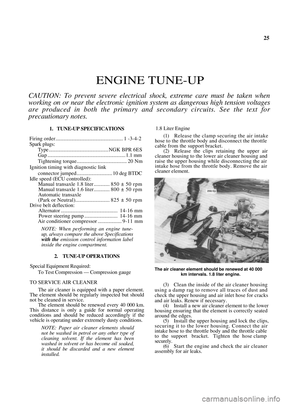
1.8 Liter Engine
(1) Release the clamp securing the air intake
hose to the throttle body and disconnect the throttle
cable from the support bracket. (2) Release the clips reta ining the upper air
cleaner housing to the lowe r air cleaner housing and
raise the upper housing while disconnecting the air
intake hose from the throttle body. Remove the air
cleaner element.
The air cleaner element should be renewed at 40 000
km intervals. 1.8 liter engine.
(3) Clean the inside of the air cleaner housing
using a damp rag to remove all traces of dust and
check the upper housing and air inlet hose for cracks
and air leaks. Renew if necessary. (4) Install a new air cleaner element to the lower
housing ensuring that the element is correctly seated
around the edges. (5) Install the upper housing and lock the clips,
securing it to the lower housing. Connect the air
intake hose to the throttle body and the throttle cable
to the support bracket. Tighten the hose clamp
securely. (6) Start the engine and check the air cleaner
assembly for air leaks.
Page 26 of 238
26 Engine Tune-up
1.6 Liter Engine
(1) Remove the nuts and washers securing the
upper air cleaner housing to the lower air cleaner
housing and release the retaining clips. (2) Remove the air cleaner element.
(3) Clean the inside of the air cleaner housing
using a damp rag to remo ve all traces of dust.
(4) Install a new air cleaner element ensuring that
the element is correctly seated around the edges.
(5) Install the upper housing and secure the
retaining clips. Tighten th e retaining nuts securely.
TO RENEW FUEL FILTER
filter should
The fuel
40 000 km.
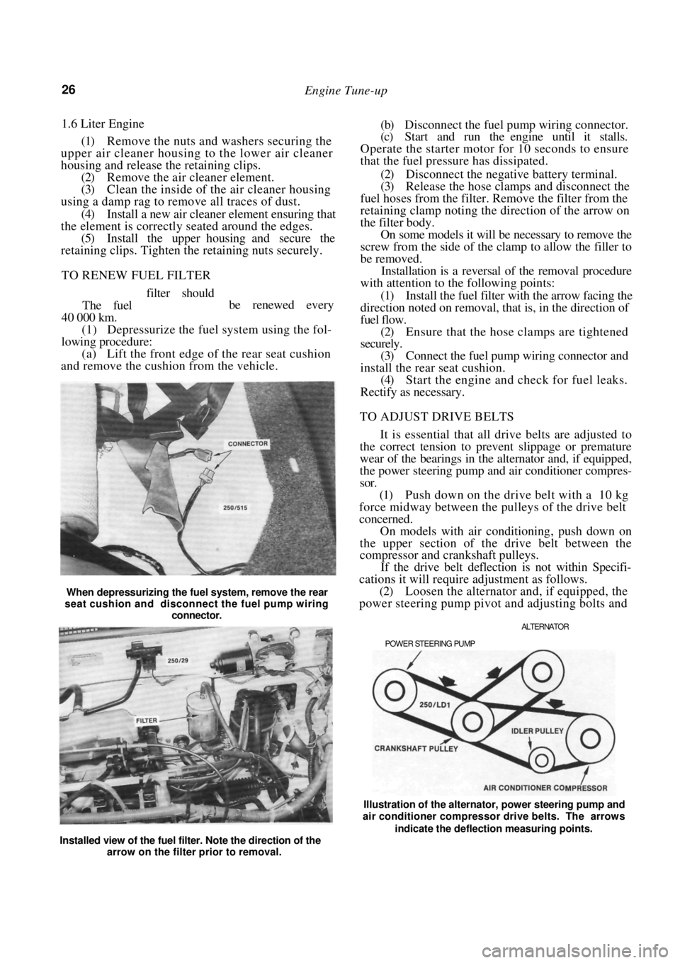
(1) Depressurize the fuel system using the fol-
lowing procedure:
(a) Lift the front edge of the rear seat cushion
and remove the cushion from the vehicle.
When depressurizing the fuel system, remove the rear
seat cushion and disconnect the fuel pump wiring
connector.
(b) Disconnect the fuel pump wiring connector.
(c) Start and run the engine until it stalls.
Operate the starter motor for 10 seconds to ensure
that the fuel pressure has dissipated.
(2) Disconnect the negative battery terminal.
(3) Release the hose clamps and disconnect the
fuel hoses from the filter. Remove the filter from the
retaining clamp noting the direction of the arrow on
the filter body. On some models it will be necessary to remove the
screw from the side of the clamp to allow the filler to
be removed.
Installation is a reversal of the removal procedure
with attention to the following points:
(1) Install the fuel filter with the arrow facing the
direction noted on removal, that is, in the direction of
fuel flow.
(2) Ensure that the hose clamps are tightened
securely.
(3) Connect the fuel pump wiring connector and
install the rear seat cushion. (4) Start the engine and check for fuel leaks.
Rectify as necessary.
TO ADJUST DRIVE BELTS
It is essential that all drive belts are adjusted to
the correct tension to prevent slippage or premature
wear of the bearings in the alternator and, if equipped,
the power steering pump and air conditioner compres-
sor.
(1) Push down on the drive belt with a 10 kg
force midway between the pulleys of the drive belt
concerned.
On models with air conditioning, push down on
the upper section of the drive belt between the
compressor and crankshaft pulleys.
If the drive belt deflection is not within Specifi-
cations it will require adjustment as follows.
(2) Loosen the alternator and, if equipped, the
power steering pump pivot and adjusting bolts and
ALTERNATOR
POWER STEERING PUMP
be renewed every
Installed view of the fuel filter. Note the direction of the arrow on the filter prior to removal. Illustration of the alternator, power steering pump and
air conditioner compressor drive belts. The arrows
indicate the deflection measuring points.
Page 27 of 238
Engine Tune-up 27
move the alternator or power steering pump as
required until the drive belt concerned has the
specified deflection.
On models with air conditioning, loosen the nut
in the centre of the idler pulley and turn the adjusting
bolt until the drive belt has the specified deflection.
(3) Tighten the alternator or power steering
pump bolts securely and check the belt tension.
On models with air conditioning, tighten the idler
pulley nut securely.
TO SERVICE SPARK PLUGS
The spark plugs should be renewed at intervals of
40 000 km.
Before removing the spark plugs ensure that the
area around each plug is cl ean to prevent foreign
matter entering the cylinder when the plugs are
removed.
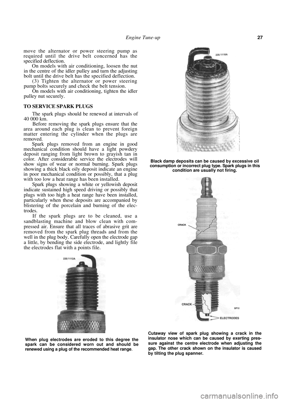
Spark plugs removed from an engine in good
mechanical condition should have a light powdery
deposit ranging from light brown to grayish tan in
color. After considerable service the electrodes will
show signs of wear or no rmal burning. Spark plugs
showing a thick black oily deposit indicate an engine
in poor mechanical condition or possibly, that a plug
with too low a heat range has been installed.
Spark plugs showing a white or yellowish deposit
indicate sustained high speed driving or possibly that
plugs with too high a heat range have been installed,
particularly when these deposits are accompanied by
blistering of the porcelain and burning of the elec-
trodes.
If the spark plugs are to be cleaned, use a
sandblasting machine and blow clean with com-
pressed air. Ensure that all traces of abrasive grit are
removed from the spark plug threads and from the
well in the plug body. Carefully open the electrode gap
a little, by bending the side electrode, and lightly file
the electrodes flat with a points file.
Black damp deposits can be caused by excessive oil
consumption or incorrect plug type. Spark plugs in this
condition are usually not firing.
Cutaway view of spark plug showing a crack in the
insulator nose which can be caused by exerting pres-
sure against the centre electrode when adjusting the
gap. The other crack shown on the insulator is caused
by tilting the plug spanner.
When plug electrodes are eroded to this degree the
spark can be considered worn out and should be
renewed using a plug of the recommended heat range
.
CRACK
Page 30 of 238
30 Engine Tune-up
(1) With the distributor cap and leads removed
as an assembly, test one lead at a time, connecting the
meter probes at the spark plug end of the lead and at
the corresponding terminal in side the cap. Resistance
should be less than 15 000 ohms.
(2) If the resistance is more than 15 000 ohms
remove the lead from the distributor cap and check
(he resistance in the lead only. The lead should be
renewed if the resistance is still more than 15 000
ohms. (3) High distributor cap resistance may be due
to corrosion deposits on the cap terminals. These
deposits should be removed with a small scraper or
emery cloth. Check the distributor cap for cracks or tracking
between the high tension terminals on both the inside
and outside of the cap. Renew the cap if cracks or
tracking are evident.
Check the carbon brush in the centre of the
distributor cap for evidence of arcing and renew as
necessary.
Check the condition of the rotor and renew if
arced excessively or cracked.
HOW TO CONNECT ELECTRICAL TEST
EQUIPMENT
NOTE: Some types of tachometers, timing
lights and ignition system analysers are not
compatible with this type of electronic igni-
tion system and may result in incorrect
readings. It is therefore recommended that
the manufacturer of the test equipment be
consulted before using the equipment.
Do not allow the tachometer lead connec-
tor to short to earth as damage to the test
equipment or ignition system may result.
Timing Light
(1) Connect the timing light to the engine fol-
lowing the instrument manufacturers instructions.
NOTE: Do not connect or disconnect the
timing light with the engine running as
voltage surges could damage the alternator.
Do not allow the high tension leads to open
circuit as damage to the ignition system
could result.
(2) Where necessary, connect the power leads of
the timing light to an external power source to prevent
possible transient voltages in the timing light damag-
ing the vehicle alternator.
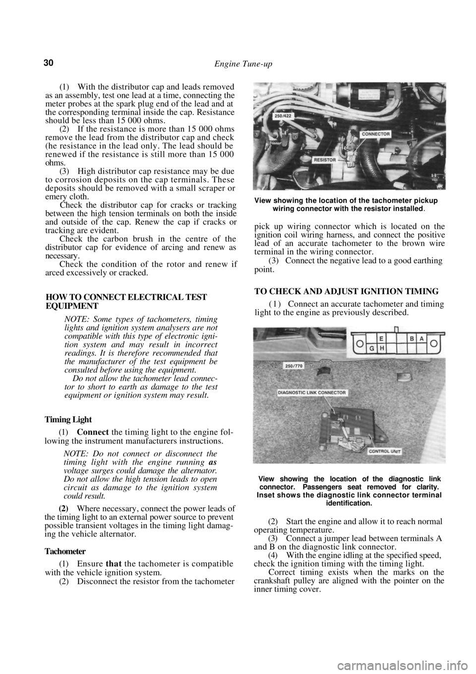
Tachometer
(1) Ensure that the tachometer is compatible
with the vehicle ignition system. (2) Disconnect the resistor from the tachometer
View showing the location of the tachometer pickup
wiring connector with the resistor installed
.
pick up wiring connector which is located on the
ignition coil wiring harness, and connect the positive
lead of an accurate tachometer to the brown wire
terminal in the wiring connector.
(3) Connect the negative lead to a good earthing
point.
TO CHECK AND ADJUST IGNITION TIMING
( 1 ) Connect an accurate tachometer and timing
light to the engine as previously described.
View showing the location of the diagnostic link
connector. Passengers seat removed for clarity.
Inset shows the diagnostic link connector terminal
identification.
(2) Start the engine and allow it to reach normal
operating temperature. (3) Connect a jumper lead between terminals A
and B on the diagnostic link connector. (4) With the engine idling at the specified speed,
check the ignition timing with the timing light.
Correct timing exists when the marks on the
crankshaft pulley are aligned with the pointer on the
inner timing cover.
Page 33 of 238
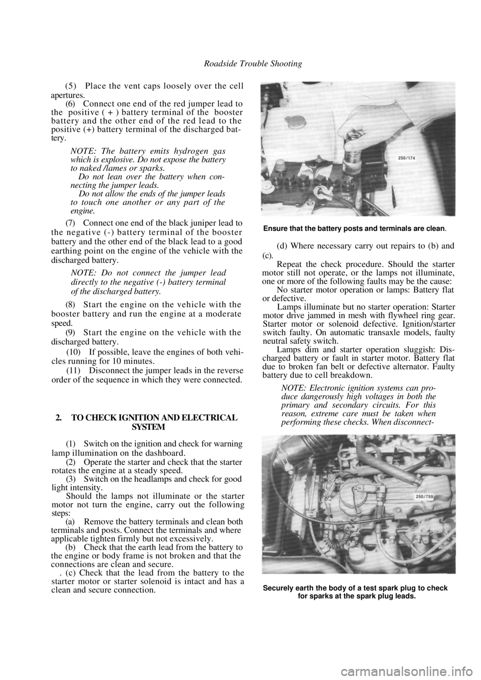
Roadside Trouble Shooting
(5) Place the vent caps loosely over the cell
apertures.
(6) Connect one end of the red jumper lead to
the positive ( + ) battery terminal of the booster
battery and the other end of the red lead to the
positive (+) battery terminal of the discharged bat-
tery.
NOTE: The battery emits hydrogen gas
which is explosive. Do not expose the battery
to naked /lames or sparks.
Do not lean over the battery when con-
necting the jumper leads.
Do not allow the ends of the jumper leads
to touch one another or any part of the
engine.
(7) Connect one end of the black juniper lead to
the negative (-) battery terminal of the booster
battery and the other end of the black lead to a good
earthing point on the engine of the vehicle with the
discharged battery.
NOTE: Do not connect the jumper lead
directly to the negative (-) battery terminal
of the discharged battery.
(8) Start the engine on the vehicle with the
booster battery and run the engine at a moderate
speed. (9) Start the engine on the vehicle with the
discharged battery.
(10) If possible, leave the engines of both vehi-
cles running for 10 minutes.
(11) Disconnect the jumper leads in the reverse
order of the sequence in which they were connected.
2. TO CHECK IGNITION AND ELECTRICAL SYSTEM
(1) Switch on the ignition and check for warning
lamp illumination on the dashboard. (2) Operate the starter and check that the starter
rotates the engine at a steady speed.
(3) Switch on the headlamps and check for good
light intensity. Should the lamps not illum inate or the starter
motor not turn the engine, carry out the following
steps:
(a) Remove the battery terminals and clean both
terminals and posts. Connect the terminals and where
applicable tighten firmly but not excessively.
(b) Check that the earth lead from the battery to
the engine or body frame is not broken and that the
connections are clean and secure. . (c) Check that the lead from the battery to the
starter motor or starter solenoid is intact and has a
clean and secure connection.
Ensure that the battery posts and terminals are clean.
(d) Where necessary carry out repairs to (b) and
(c).
Repeat the check procedur e. Should the starter
motor still not operate, or the lamps not illuminate,
one or more of the following faults may be the cause:
No starter motor operation or lamps: Battery flat
or defective.
Lamps illuminate but no starter operation: Starter
motor drive jammed in mesh with flywheel ring gear.
Starter motor or solenoid defective. Ignition/starter
switch faulty. On automatic transaxle models, faulty
neutral safety switch.
Lamps dim and starter operation sluggish: Dis-
charged battery or fault in starter motor. Battery flat
due to broken fan belt or de fective alternator. Faulty
battery due to cell breakdown.
NOTE: Electronic ignition systems can pro-
duce dangerously high voltages in both the
primary and secondary circuits. For this
reason, extreme care must be taken when
performing these checks. When disconnect-
Securely earth the body of a test spark plug to check
for sparks at the spark plug leads.
Page 42 of 238

42 Engine
The cylinder block is a cast iron alloy, deep skirt
design and the crankshaft is supported in the cylinder
block by five precision insert replaceable main bear-
ings. Crankshaft end float is controlled by the flanged
centre main bearing. Connecting rods are I section
forgings equipped with precision insert replaceable big
end bearings. The gudgeon pins are an interference fit
in the connecting rod and a floating fit in the piston.
The cast aluminum pistons are equipped with
two compression rings and one oil control ring.
The twin rotor, involute gear oil pump is mounted
directly to the front face of the cylinder block. The
inner rotor is internally driven by the crankshaft. The
oil pump pressure relief valve is not adjustable, and
consists of a plunger and spring mounted in the oil
pump body.
The pump draws oil through a screen in the sump
and delivers it, via a full flow replaceable oil filter, to
the oil gallery from where it is distributed to the
hydraulic tappets, camshaft and crankshaft bearings
and to the overhead rocker and valve mechanism.
3. ENGINE AND TRANSAXLE ASSEMBLY
Special Equipment Required:
To Remove and Instill — Suitable lifting tackle,
extra long chassis stands, suitable trolley
TO REMOVE
NOTE: Due to the high residual pressure
within the fuel system, it will be necessary to
depressurize the system before removing any
fuel supply components. Refer to the Fuel
and Engine Management section for the
correct procedure.
(1) Disconnect the negative battery terminal.
(2) Mark around the bonnet hinges with a soft
lead pencil Co facilitate correct installation. With the
aid of an assistant, remove the bonnet retaining bolts
and remove the bonnet from the vehicle.
(3) Drain the engine and transaxle lubricant.
(4) Open the coolant drain tap located on the
lower radiator pipe and drain the coolant. (5) Loosen the hose clips and disconnect the
heater hoses from the heater pipes at the bulkhead.
NOTE: Do not use excessive force to remove
the heater hoses from the heater pipes or the
heater core will become dislodged from the
heater unit. If necessary, cut the heater
hoses from the pipes using a sharp knife.
(6) Loosen the hose clamps and disconnect the
radiator hoses from the engine assembly. (7) Disconnect the positive lead from the bat-
tery. (8) On 1.8 liter models, disconnect the air inlet
duct.
(9) On 1.6 liter models, remove the air cleaner
assembly. Refer to the Fuel and Engine Management
section if necessary. (10) Disconnect the throttle cable from the throt-
tle body and from the camshaft housing top cover
bracket, if applicable. (11) Disconnect the fuel supply and return hoses.
Mark the hoses as an aid to installation. (12) Suitably mark and disconnect the charcoal
canister hoses. (13) Disconnect the injector wires from the injec-
tors. On 1.6 liter models, slide the wiring out from the
throttle body. (14) Disconnect the wiring fr om the throttle po-
sition sensor (TPS), idle air control (IAC) valve,
oxygen (O
2) sensor wire, coolant temperature sensor,
coolant sender and on 1.8 liter models, the manifold
air temperature (MAT) sensor. (15) Disconnect the wiring connector adjacent to
the top heater hose, the wiring from the alternator and
the two earth wires from underneath the cylinder head
bolts. (16) Lay the wiring loom over on the passenger
side of the engine compar tment, clear of the work
area.
(17) On manual transaxle models, loosen the
clutch cable adjusting nuts and remove the cable
through the slot in the lever. Remove the clutch cable
bracket from the transaxle after removing the retain-
ing bolts and place the cable to one side.
(18) Disconnect the wiring from the starter mo-
tor, speedometer sender and on manual transaxle
models, the reverse lamp switch wiring.
(19) If applicable, disconnect the power steering
lines from the pump and drain the fluid into a
container. Suitably plug the lines and the pump to
prevent the entry of dirt.
(20) On automatic transaxle models, disconnect
the selector cable and bracket from the transaxle
assembly.
Disconnect the transaxle oil cooler lines from the
transaxle. Plug the lines and fittings to prevent the
entry of dirt etc.
(21) Loosen the front wheel nuts, raise the front
of the vehicle and support it on extra long chassis
stands. Ensure that the vehicle is high enough to allow
removal of the engine from underneath. (22) Remove the front wheels and the engine
splash guards from the vehicle.
(23) On manual transaxle models, remove the
stay rod and control rod bolts and nuts and disconnect
the rods from the transaxle.
(24) Remove the lower control arm to steering
knuckle ball joint nuts and separate the ball joints
from the steering knuckle by holding a dolly or a
hammer against one side of the steering knuckle and
hitting the other side with a hammer. The taper on the
ball joint will release fr om the steering knuckle.
(25) Pull the steering knuckles outward swiftly to
Page 46 of 238
46 Engine
(1) Ensure that all carbon and old gasket mate-
rial is cleaned from the manifold and cylinder head
faces. (2) Check the face of the manifold for distortion
using a straight edge and a feeler gauge. (3) Use a new gasket and ensure that the mani-
fold retaining nuts are tightened to the specified
torque in a spiral pattern from the centre outwards. (4) Adjust the throttle cabl e as described in the
Fuel and Engine Management section and the kick-
down cable as described in the Automatic Transaxle
section.
(5) Start the engine and check for air, fuel and
water leaks.
EXHAUST MANIFOLD
To Remove and Install
(1) Bring the engine to operating temperature
and remove the oxygen sensor.
(2) Disconnect the negative battery terminal.
(3) On 1.6 liter models, remove the air cleaner
nuts, disconnect the vacuum hose and withdraw the
air cleaner from the vehicle. (4) Remove the front exhaust pipe flange mount-
ing nuts and separate the exhaust pipe from the
manifold. (5) Remove the heat shield retaining bolts and
withdraw the heat shield from the exhaust manifold. (6) Remove the exhaust manifold to cylinder
head retaining nuts and remove the manifold from the
engine. Discard the manifold gasket. Installation is a reversal of the removal procedure
with attention to the following points:
(1) Ensure that all carbon is cleaned from the
manifold and cylinder head mating surfaces. (2) Check the face of the manifold for distortion
using a straight edge and feeler gauges. (3) Use new gaskets on assembly.
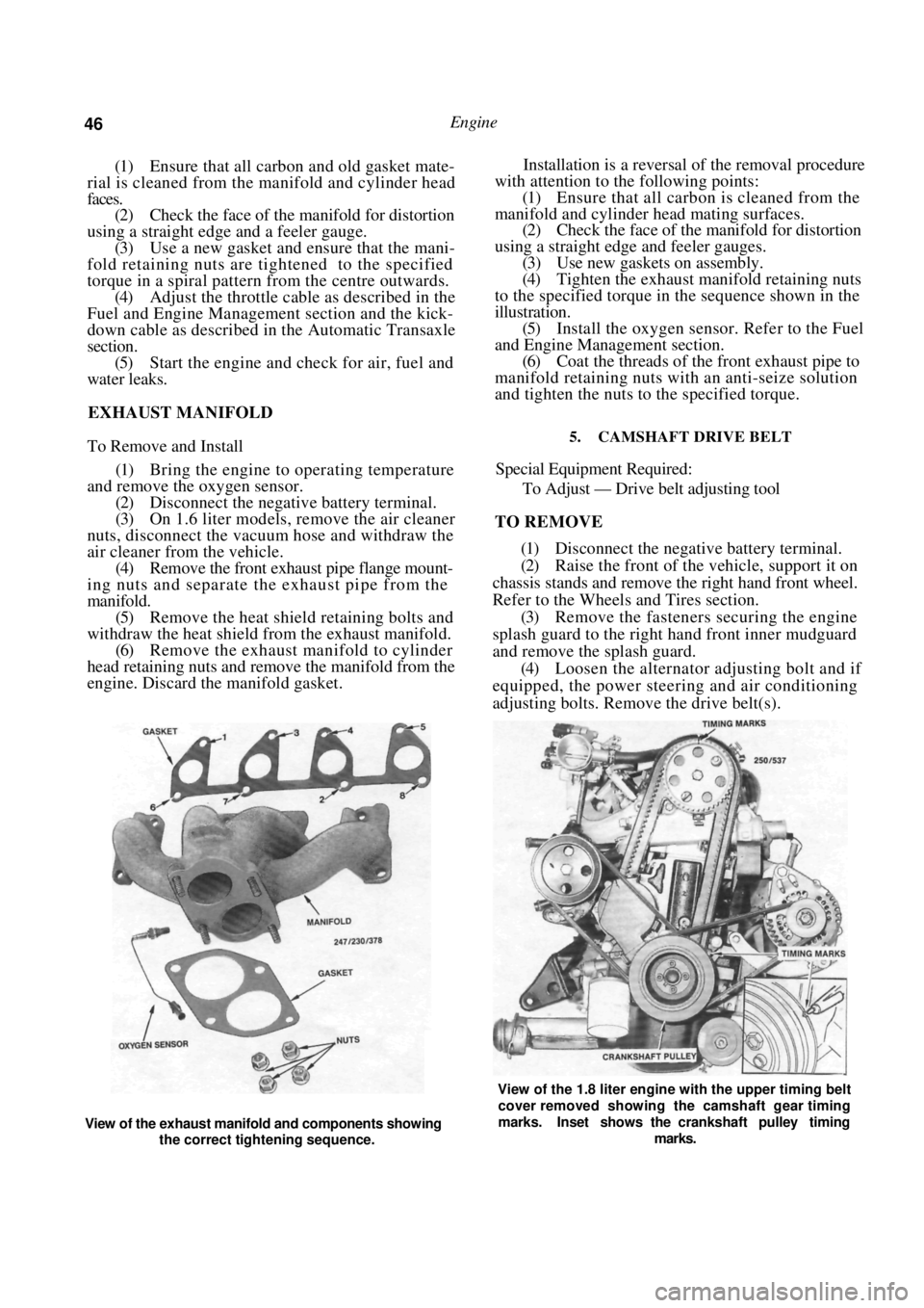
(4) Tighten the exhaust manifold retaining nuts
to the specified torque in the sequence shown in the
illustration. (5) Install the oxygen sensor. Refer to the Fuel
and Engine Management section. (6) Coat the threads of the front exhaust pipe to
manifold retaining nuts with an anti-seize solution
and tighten the nuts to the specified torque.
5. CAMSHAFT DRIVE BELT
Special Equipment Required:
To Adjust — Drive belt adjusting tool
TO REMOVE
(1) Disconnect the negative battery terminal.
(2) Raise the front of the vehicle, support it on
chassis stands and remove the right hand front wheel.
Refer to the Wheels and Tires section. (3) Remove the fasteners securing the engine
splash guard to the right hand front inner mudguard
and remove the splash guard. (4) Loosen the alternator adjusting bolt and if
equipped, the power steering and air conditioning
adjusting bolts. Remove the drive belt(s).
View of the exhaust manifold and components showing
the correct tightening sequence.
View of the 1.8 liter engine with the upper timing belt
cover removed showing the camshaft gear timing
marks. Inset shows the crankshaft pulley timing
marks.
Page 48 of 238
48 Engine
TO INSTAL
(1) Check that the camshaft and crankshaft
timing gears have not been moved and that the timing
marks are still aligned. It will be necessary to tempo-
rarily install the crankshaft pulley to check that the
timing marks are still aligned. (2) Install the drive belt to the crankshaft timing
gear around the water pump gear and onto the
camshaft timing gear.
NOTE: If the original drive belt is being
installed, ensure that the arrow marked on
the belt prior to removal is pointing in the
direction of rotation.
(3) Use the adjusting tool to turn the water
pump assembly sufficiently to engage the water pump
pulley with the drive belt. (4) Install the inner cover lower retaining bolt.
(5) Ensure that the drive be lt is correctly meshed
with the teeth of the camshaft, crankshaft and water
pump gears. Install the crankshaft pulley and tighten
the bolts to Specifications. (6) Adjust the drive belt as described under the
following heading.
(7) Install the drive belt outer cover and fasten
the retaining clips. (8) Install and adjust the alternator and if
equipped, the power steeri ng and air conditioning
drive belts as desc ribed in the Engine Tune-up section.
TO ADJUST
(1) Remove the alternator drive belt and if
equipped, the power steering and air conditioning
drive belts. (2) Release the clips securing the camshaft drive
belt outer cover to the inner cover and remove the
outer cover. (3) Turn the engine in the direction of rotation
until the timing marks on the camshaft and the inner
cover are aligned. (4) Loosen the water pump retaining bolts and
using the adjusting tool, rotate the water pump
housing to gain the required belt tension. The belt is
correctly tensioned when it can be grasped between
the thumb and forefinger midway between the cam-
shaft timing gear and the water pump gear and turned
ninety degrees from i t s operating position.
After the belt has been tensioned, tighten the
water pump retaining bolts to the specified torque.
NOTE: Over tensioning of the drive belt will
result in noisy operation and premature
wear of the belt.
(6) Install the outer drive belt cover.
(7) Install and adjust the alternator, and if
equipped, the power steering and air conditioning
drive belts as desc ribed in the Engine Tune-up section. 6. CAMSHAFT. ROCKER ARMS AND TAPPETS
Special Equipment Required:
To Check Camshaft — Dial gauge, Vee blocks and
micrometers
To Install — Drive belt adjusting tool
It is recommended that a new cylinder head
gasket is installed and the cylinder head bolts renewed
when the camshaft housing is removed.
TO REMOVE
(1) Disconnect the negative battery terminal.
Remove the nuts securing the earth wires to the
cylinder head bolts and remove the earth wires.
(2) On 1.6 liter models, remove the air cleaner
wingnuts and withdraw the air cleaner.
(3) Disconnect the engine breather hoses from
the camshaft housing and the camshaft housing top
cover. (4) Remove the camshaft housing top cover
retaining bolts and remove the top cover. Discard the
gasket.
(5) Remove the camshaft dr ive belt as described
under the previous heading. (6) Using an open ended spanner, hold the
camshaft between the inle t and exhaust lobes of
number four cylinder and remove the camshaft timing
gear retaining bolt and the camshaft timing gear.
(7) Remove the distributor, distributor cap and
high tension leads. If necessary refer to the Fuel and
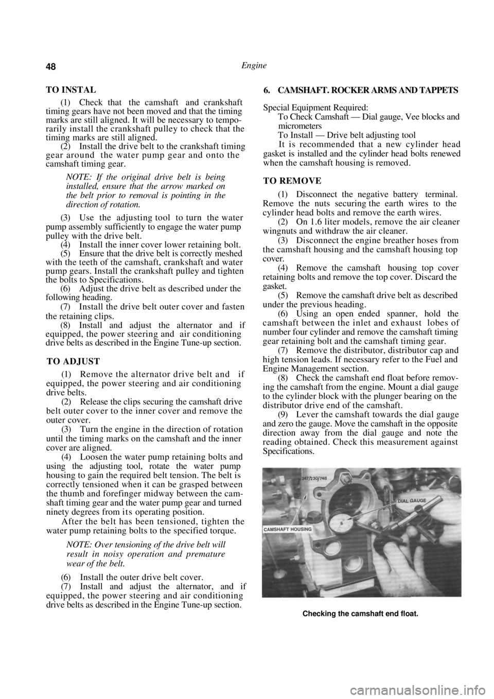
Engine Management section. (8) Check the camshaft end float before remov-
ing the camshaft from the engine. Mount a dial gauge
to the cylinder block with the plunger bearing on the
distributor drive end of the camshaft. (9) Lever the camshaft towards the dial gauge
and zero the gauge. Move the camshaft in the opposite
direction away from the dial gauge and note the
reading obtained. Check this measurement against
Specifications.
Checking the camshaft end float.
Page 50 of 238

50 Engine
(4) Ensure that the tappet assemblies are full of
clean engine oil and insert the tappets in their
respective bores in the cylinde r head. Install the thrust
pads to the top of each valve assembly ensuring that
they are returned to their original location.
(5) Coat the contact surfaces of the rocker arms
with molybdenum disulphide grease and install the
rocker arms to their origin al locations on the cylinder
head. (6) Clean the mating surfaces of the camshaft
housing and cylinder head. Apply a bead of Loctite
515 to the cylinder head and camshaft housing mating
surfaces. Take care that no sea lant is forced into the
oil passages and install the camshaft housing to the
cylinder head.
(7) Install new cylinder head bolts and lubricate
the bolts and washers with oil.
(8) Apply an initial torque to the cylinder head
bolts of 25 Nm in the corr ect sequence as shown in
the illustration under the Cylinder Head heading.
Further tighten the head bolts in the correct sequence,
in three separate 60 degree stages. Refer to Specifica-
tions. (9) Install the bolts securing the camshaft
drive
belt inner cover to the camshaft housing. (10) Install the camshaft timing gear to the cam-
shaft ensuring that it is correctly located. Tighten the
camshaft timing gear retain ing boll to the specified
torque. (11) Install and adjust the camshaft drive belt as
described under the previous heading. (12) Install the distributor. Refer to the Fuel and
Engine Management section.
(13) Connect the lower radiat or hose and fill the
cooling system with the required coolant. Refer to the
Cooling and Heating Systems section if necessary. (14) Start and run the engine until normal oper-
ating temperature is attained and tighten the cylinder
head bolts another 30-50 degrees in the correct
sequence, ensuring that the tension does not exceed
135 Nm.
TO RENEW CAMSHAFT OIL SEAL,
CAMSHAFT INSTALLED
(1) Remove the camshaft drive belt from the
camshaft timing gear as described under the previous
heading.
(2) Remove the camshaft housing top cover
retaining bolts, remove the cover and discard the
gasket.
(3) Use an open end spanner to hold the cam-
shaft between the inlet and exhaust lobes of number
four cylinder and remove the camshaft timing gear
retaining bolt and the camshaft timing gear. (4) With a pointed drift, tap a small hole in the
front face of the oil seal. Insert a self tapping screw in
the hole and using a pair of pliers, pull on the screw
to remove the oil seal from the housing.
(5) Clean the seal recess and the camshaft sea!
running surface. (6) Lubricate the lip of a new oil seal with engine
oil and slide the seal over the camshaft. Ensure that
the lip of the seal faces to wards the inside of the
camshaft housing. Tap evenly around the edges of the
seal until it is fully seated in the camshaft housing.
(7) Install the camshaft timing gear to the cam-
shaft, ensuring that it is co rrectly located. Tighten the
camshaft timing gear retain ing bolt to the specified
torque. Do not allow the camshaft to rotate while
tightening the bolt. (8) Install and adjust the drive belt as described
under the previous heading. Ensure that the timing
marks are aligned. (9) Install the camshaft hou sing top cover using a
new gasket. Tighten the retaining bolts to the specified
torque.
7. CYLINDER HEAD
Special Equipment Required:
To Dismantle and Assemble — Valve spring com-
pressor
To Inspect — Dial gauge and straight edge
To Install — Drive belt adjusting tool
TO REMOVE AND INSTAL
NOTE: Due to the high residua! pressure
within the fuel system, it will be necessary to
depressurize the system before removing any
fuel supply components. Refer to the Fuel
and Engine Management section for the
correct procedure.
Allow the engine to cool prior to the
removal of the cylinder head to prevent
possible distortion of the cylinder head.
(1) Disconnect the negative battery terminal and
remove the nuts securing the earth wires to the
cylinder head bolts.
(2) Remove the camshaft drive belt as previ-
ously described.
(3) Disconnect the lower radiator hose and drain
the cooling system. Refer to the Cooling and Heating
Systems section if necessary. (4) Remove the alternator adjusting bracket
mounting bolt and insulating washers from the inlet
manifold. Loosen the adjusting bolt at the alternator
and slide the bracket away from the cylinder head. (5) Disconnect the upper radiator hose, coolant
by-pass hose and the heater hose from the thermostat
housing and on 1.6 liter m odels, the coolant hoses
from the inlet manifold. (6) Disconnect the electrica l connectors from the
throttle body, fuel injectors, coil, distributor and on
1.8 liter models, the MAT sensor. (7) Disconnect the oxygen sensor wiring connec-
tor and remove the wiring connectors from the