alternator NISSAN PULSAR 1987 User Guide
[x] Cancel search | Manufacturer: NISSAN, Model Year: 1987, Model line: PULSAR, Model: NISSAN PULSAR 1987Pages: 238, PDF Size: 28.91 MB
Page 89 of 238
Fuel and Engine Management 89
The procedure for fabricating an LED test lamp is
fully described in the El ectrical System section.
If a conventional test lamp with a filament type
bulb is to be used, ensure that the current draw of the
test lamp does not exceed 0.3 amp to avoid damage to
the electronic components.
To check the current draw connect an accurate
ammeter, such as the multimeter described previ-
ously, in series with the test lamp and a battery.
If the ammeter reads less than 0.3 amp the test
lamp is suitable.
Tachometer
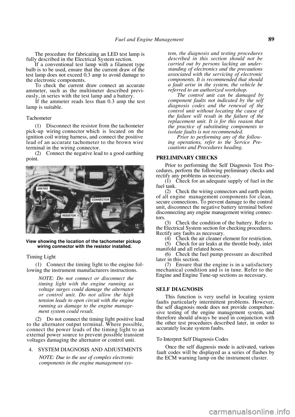
(1) Disconnect the resistor from the tachometer
pick-up wiring connector which is located on the
ignition coil wiring harness, and connect the positive
lead of an accurate tachometer to the brown wire
terminal in the wiring connector. (2) Connect the negative lead to a good earthing
point.
View showing the location of the tachometer pickup
wiring connector with the resistor installed.
Timing Light
(1) Connect the timing light to the engine fol-
lowing the instrument manufacturers instructions.
NOTE: Do not connect or disconnect the
timing light with the engine running as
voltage surges could damage the alternator
or control unit. Do not allow the high
tension leads to open circuit with the engine
running as damage to the engine manage-
ment system could result.
(2) Do not connect the timing light positive lead
to the alternator output terminal. Where possible,
connect the power leads of the timing light to an
external power source to prevent possible transient
voltages damaging the alternator or control unit.
4. SYSTEM DIAGNOSIS AND ADJUSTMENTS
NOTE: Due to the use of complex electronic
components in the engine management sys-
tem, the diagnosis and testing procedures
described in this section should not be
carried out by persons lacking an under-
standing of electronics and the precautions
associated with the servicing of electronic
components. It is rec ommended that should
a fault arise in the system, the vehicle be
referred to an authorized workshop.
The control unit can be damaged by
component faults not indicated by the self
diagnosis codes and the renewal of the
control unit without lo cating the cause of
the failure will result in the failure of the
replacement unit. It is for this reason that
the practice of substituting components to
isolate faults is not recommended.
Prior to performing any of the follow-
ing operations, refer to the Service Pre-
cautions and Procedures heading.
PRELIMINARY CHECKS
Prior to performing the Self Diagnosis Test Pro-
cedures, perform the following preliminary checks and
rectify any problems as necessary.
(1) Check for an adequate supply of fuel in the
fuel tank. (2) Check the wiring connectors and earth points
of all engine management components for clean,
secure connections. To prevent damage to the control
unit, disconnect the negative battery terminal before
disconnecting any engine ma nagement wiring connec-
tors. (3) Check the condition of the battery. Refer to
the Electrical System sectio n for checking procedures.
Rectify any faults as necessary. (4) Check the air cleaner element for restriction.
(5) Check for air leaks at the throttle body, inlet
manifold and all related hoses. (6) Check the fuel pump pr essure as described
later in this section. (7) Ensure that the engine is in a satisfactory
mechanical condition and is in tune. Refer to the
Engine and Engine Tune-up sections as necessary.
SELF DIAGNOSIS
This function is very useful in locating system
faults particularly intermittent problems. However,
the self diagnosis mode does not provide comprehen-
sive testing of the engine management system, and
therefore should always be used in conjunction with
the other test procedures described later, in order to
accurately locate system faults.
To Interpret Self Diagnosis Codes
Once the self diagnosis mode is activated, various
fault codes will be displayed as a series of flashes by
the ECM warning lamp on the instrument cluster.
Page 101 of 238
Fuel and Engine Management 101
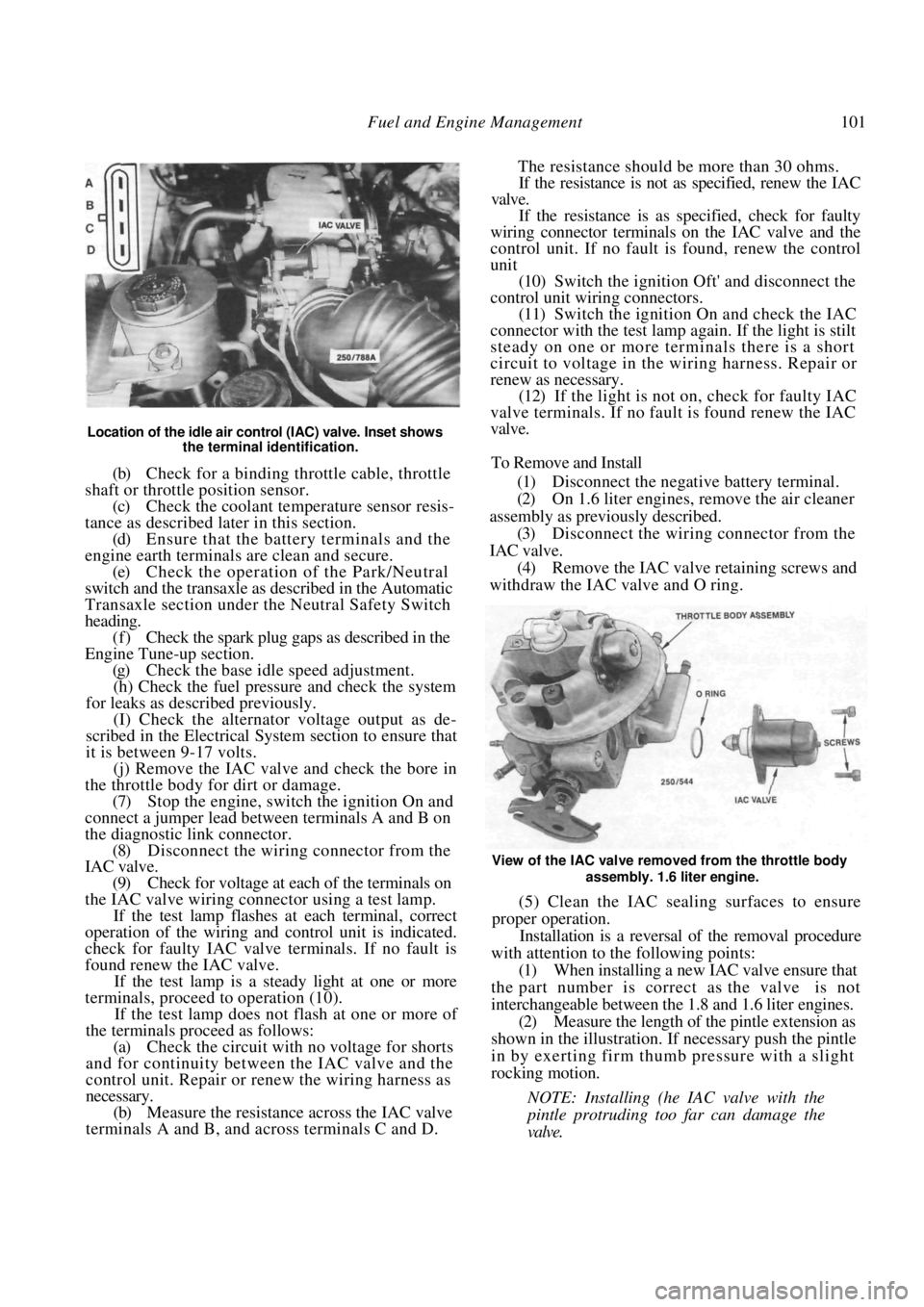
Location of the idle air control (IAC) valve. Inset shows the terminal identification.
(b) Check for a binding throttle cable, throttle
shaft or throttle position sensor. (c) Check the coolant temperature sensor resis-
tance as described later in this section. (d) Ensure that the battery terminals and the
engine earth terminals are clean and secure.
(e) Check the operation of the Park/Neutral
switch and the transaxle as described in the Automatic
Transaxle section under the Neutral Safety Switch
heading. (f) Check the spark plug gaps as described in the
Engine Tune-up section.
(g) Check the base idle speed adjustment.
(h) Check the fuel pressure and check the system
for leaks as described previously.
(I) Check the alternator voltage output as de-
scribed in the Electrical System section to ensure that
it is between 9-17 volts.
(j) Remove the IAC valve and check the bore in
the throttle body for dirt or damage.
(7) Stop the engine, switch the ignition On and
connect a jumper lead between terminals A and B on
the diagnostic link connector. (8) Disconnect the wiring connector from the
IAC valve.
(9) Check for voltage at each of the terminals on
the IAC valve wiring connector using a test lamp. If the test lamp flashes at each terminal, correct
operation of the wiring and control unit is indicated.
check for faulty IAC valve terminals. If no fault is
found renew the IAC valve.
If the test lamp is a steady light at one or more
terminals, proceed to operation (10).
If the test lamp does not flash at one or more of
the terminals proceed as follows:
(a) Check the circuit with no voltage for shorts
and for continuity between the IAC valve and the
control unit. Repair or renew the wiring harness as
necessary.
(b) Measure the resistance across the IAC valve
terminals A and B, and across terminals C and D. The resistance should be more than 30 ohms.
If the resistance is not as specified, renew the IAC
valve.
If the resistance is as specified, check for faulty
wiring connector terminals on the IAC valve and the
control unit. If no fault is found, renew the control
unit
(10) Switch the ignition Oft' and disconnect the
control unit wiring connectors. (11) Switch the ignition On and check the IAC
connector with the test lamp again. If the light is stilt
steady on one or more terminals there is a short
circuit to voltage in the wiring harness. Repair or
renew as necessary. (12) If the light is not on, check for faulty IAC
valve terminals. If no fault is found renew the IAC
valve.
To Remove and Install
(1) Disconnect the negative battery terminal.
(2) On 1.6 liter engines, remove the air cleaner
assembly as previously described. (3) Disconnect the wiring connector from the
IAC valve. (4) Remove the IAC valve retaining screws and
withdraw the IAC valve and O ring.
View of the IAC valve removed from the throttle body
assembly. 1.6 liter engine.
(5) Clean the IAC sealing surfaces to ensure
proper operation.
Installation is a reversal of the removal procedure
with attention to the following points:
(1) When installing a new IAC valve ensure that
the part number is correct as the valve is not
interchangeable between the 1.8 and 1.6 liter engines.
(2) Measure the length of the pintle extension as
shown in the illustration. If necessary push the pintle
in by exerting firm thum b pressure with a slight
rocking motion.
NOTE: Installing (he IAC valve with the
pintle protruding too far can damage the
valve.
Page 190 of 238

190
ELECTRICAL SYSTEM
CAUTION: To prevent severe electrical shock extreme care must be taken when
working on or near the electronic ignition system as dangerous high tension voltages
are produced in both the primary and secondary circuits. See the text fo\
r
precautionary notes.
SPECIFICATIONS
BATTERY
Type ..................................................12 volt lead acid
Polarity to earth .................................... Negative ( - )
Specific gravity:
Fully charged ................................... A bove 1.250
Fully discharged ................................Below 1.130
ALTERNATOR
Make .................................................Bosch or Hitachi
Maximum output .......................................... 70 amps
Polarity to earth .................................... Negative ( - )
Stator windings ......................................... Star wound
Regulator type ................................................ Integral
Brush length minimum:
Bosch ........................................................ 5.0 mm
Hitachi ............................. 6.0 mm or limit mark
STARTER MOTOR
Make .................................................Hitach i or Bosch
Type ............................ 4 pole 4 brush reduction gear
Operation control.................................. Solenoid and
overrunning clutch
Undercut of commutator (maximum):
Hitachi ...................................................... 0.8 mm
Brush length (minimum):
Bosch ........................................................ 8.0 mm
Hitachi ........................................................11 mm
Brush spring tension;
Hitachi ............................................... 15.7-19.6 N
Hitachi:
Drive pinion stopper clearance ........ 0.3-1.5 mm
Selective fit adjuster plates ........ 0.5 and 0.8 mm
IGNITION SYSTEM
The ignition system is an integral part of the
engine management system. The Specifications, testing
and overhaul procedures are fully covered in the Fuel
and Engine Management section.
TORQUE WRENCH SETTINGS
Alternator pulley retaining nut:
Bosch ......................................................... 50 Nm
Hitachi ....................................................... 59 Nm
1. BATTERY AND CHARGING SYSTEM
TROUBLE SHOOTING
BATTERY UNDERCHARGED
3. Loose or broken drive belt: Adjust or renew
the drive belt. 4. Faulty alternator regulator; Renew the regu-
lator unit.
5. Faulty battery: Install a new battery of
the
recommended type and capacity. 6. Faulty alternator: Overhaul or renew the
alternator. 7. Fault in the charging circuit wiring: Check
and repair or renew the wiring harness. 8. Faulty connections in the charging circuit:
Check and repair the connections. 9. Fusible link blown; Rectify the fault and
renew as necessary.
NOTE: Check the state of charge (specific
gravity) of the battery- as described under
the
Battery heading in this section. If the battery
is undercharged, check the possible causes in
the order given.
BATTERY OVERCHARGED
• Faulty alternator regulator unit:
Renew the
regulator unit.
• Faulty alternator: Overhaul or
renew the
alternator. • Faulty charging circuit wiring or
connec-
tions: Check and renew or repair the faulty
compo-
nents.
NOTE: An overcharged battery is indicated
by continual loss of water through boiling.
Page 191 of 238
Electrical System 191
This is usually accompanied by discoloura-
tion of the electrolyte.
CHARGE INDICATOR LAMP REMAINS ON
• Loose or broken alternator drive belt: Adjust
or renew the drive belt.
• Faulty regulator unit: Check and renew the
regulator unit. • Faulty alternator: Check and overhaul the
alternator. • Short to earth in the warning lamp circuit:
Check and repair the circuit.
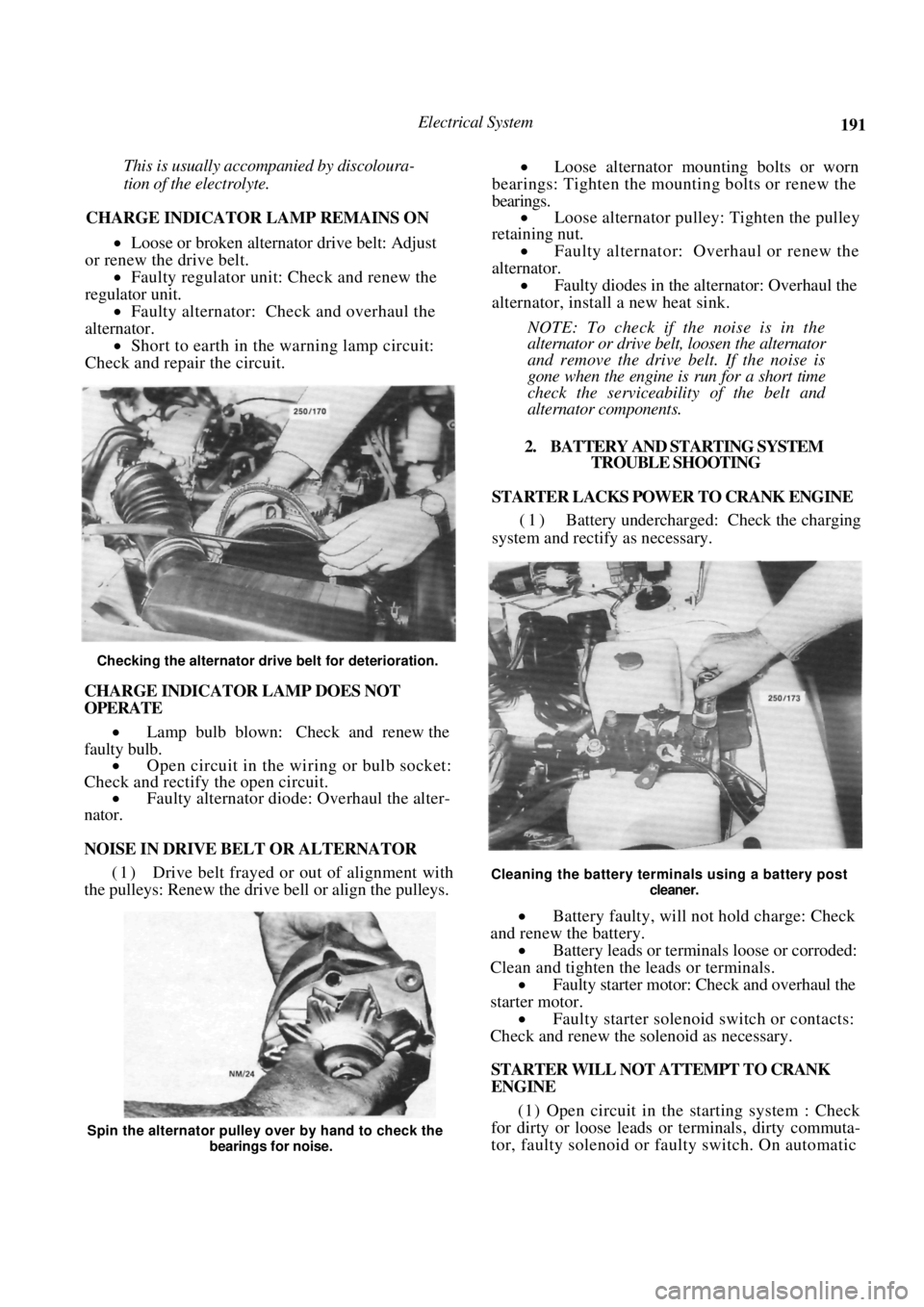
Checking the alternator drive belt for deterioration.
CHARGE INDICATOR LAMP DOES NOT
OPERATE
• Lamp bulb blown: Check and renew the
faulty bulb. • Open circuit in the wi ring or bulb socket:
Check and rectify the open circuit. • Faulty alternator diode: Overhaul the alter-
nator.
NOISE IN DRIVE BELT OR ALTERNATOR
(1) Drive belt frayed or out of alignment with
the pulleys: Renew the drive bell or align the pulleys.
• Loose alternator moun ting bolts or worn
bearings: Tighten the mounting bolts or renew the
bearings. • Loose alternator pulley: Tighten the pulley
retaining nut.
• Faulty alternator: Overhaul or renew the
alternator. • Faulty diodes in the alternator: Overhaul the
alternator, install a new heat sink.
NOTE: To check if the noise is in the
alternator or drive belt, loosen the alternator
and remove the drive belt. If the noise is
gone when the engine is run for a short time
check the serviceability of the belt and
alternator components.
2. BATTERY AND STARTING SYSTEM TROUBLE SHOOTING
STARTER LACKS POWER TO CRANK ENGINE
(1) Battery undercharged: Check the charging
system and rectify as necessary.
Cleaning the battery terminals using a battery post
cleaner.
• Battery faulty, will not hold charge: Check
and renew the battery. • Battery leads or terminals loose or corroded:
Clean and tighten the leads or terminals.
• Faulty starter motor: Check and overhaul the
starter motor. • Faulty starter solenoid switch or contacts:
Check and renew the solenoid as necessary.
STARTER WILL NOT ATTEMPT TO CRANK
ENGINE
(1 ) Open circuit in the starting system : Check
for dirty or loose leads or terminals, dirty commuta-
tor, faulty solenoid or faulty switch. On automatic
Spin the alternator pulley over by hand to check the
bearings for noise.
Page 192 of 238
192 Electrical System
transaxle models, check for a faulty or incorrectly
adjusted neutral safety switch.
1. Discharged battery: Check for a fault or short
circuit in the system. 2. Battery fully charged but will not crank
engine. Check for a locked drive and ring gear,
internal starter faul t or seized engine.
3. Fusible link blown: Check and repair the
cause and renew as necessary.
NOTE: Rotate the engine by hand to ensure
that the starter drive is not locked with the
flywheel ring gear and t hat the engine is not
seized. Ensure that the ignition key is
turned off before rotating the engine.
3. LIGHTING SYSTEM TROUBLE SHOOTING
LAMP OR LAMPS FAIL TO LIGHT
1. Faulty bulb(s): Check and renew the faulty
bulb(s). 2. Open circuit in the wiring or connections:
Check the lamp circuits and rectify as necessary.
1. Faulty lamp switch: Check and if necessary
renew the lamp switch. 2. Faulty fuse or fuse connection: Repair the
fuse connection or renew the fuse. 3. Lamp relay faulty: Check and renew as
necessary.
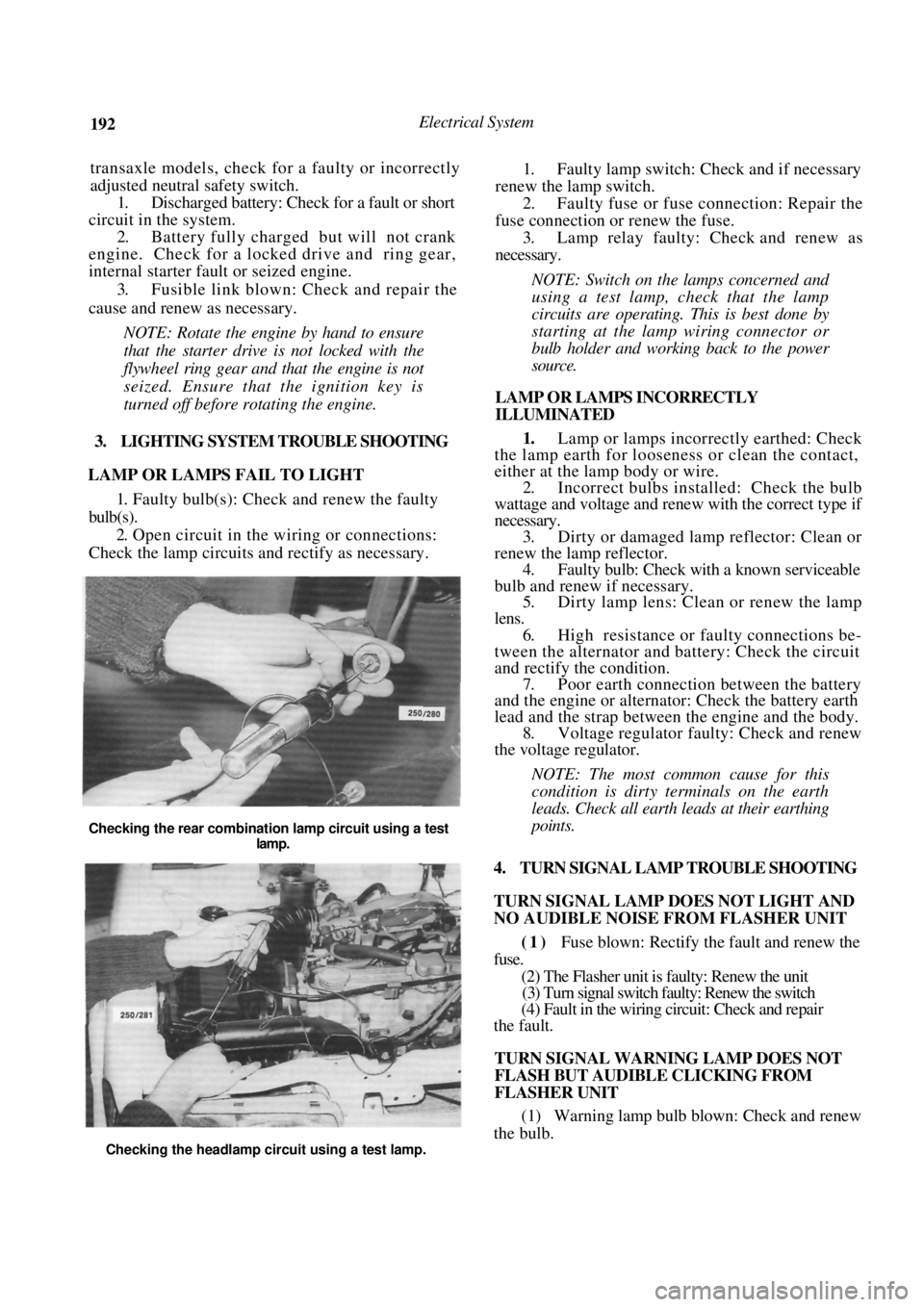
NOTE: Switch on the lamps concerned and
using a test lamp, check that the lamp
circuits are operating. This is best done by
starting at the lamp wiring connector or
bulb holder and work ing back to the power
source.
LAMP OR LAMPS INCORRECTLY
ILLUMINATED
1. Lamp or lamps incorrectly earthed: Check
the lamp earth for loosene ss or clean the contact,
either at the lamp body or wire.
2. Incorrect bulbs installe d: Check the bulb
wattage and voltage and renew with the correct type if
necessary. 3. Dirty or damaged lamp reflector: Clean or
renew the lamp reflector. 4. Faulty bulb: Check with a known serviceable
bulb and renew if necessary. 5. Dirty lamp lens: Clean or renew the lamp
lens. 6. High resistance or faulty connections be-
tween the alternator and battery: Check the circuit
and rectify th e condition.
7. Poor earth connection between the battery
and the engine or alternat or: Check the battery earth
lead and the strap between the engine and the body. 8. Voltage regulator faulty: Check and renew
the voltage regulator.
NOTE: The most common cause for this
condition is dirty t erminals on the earth
leads. Check all earth leads at their earthing
points.
4. TURN SIGNAL LAMP TROUBLE SHOOTING
TURN SIGNAL LAMP DOES NOT LIGHT AND
NO AUDIBLE NOISE FROM FLASHER UNIT
(1) Fuse blown: Rectify the fault and renew the
fuse.
(2) The Flasher unit is faulty: Renew the unit
(3) Turn signal switch faulty: Renew the switch
(4) Fault in the wiring circuit: Check and repair
the fault.
TURN SIGNAL WARNING LAMP DOES NOT
FLASH BUT AUDIBLE CLICKING FROM
FLASHER UNIT
(1) Warning lamp bulb blown: Check and renew
the bulb.
Checking the rear combination lamp circuit using a test
lamp.
Checking the headlamp circuit using a test lamp.
Page 195 of 238
Electrical System 195
(2) Remove the battery holding clamp and lift
the battery from the vehicle.
Installation is a reversal of the removal procedure
with attention to the following points:
Ensure that the terminals and posts are
clean. When connecting the l eads to the battery,
ensure that the polarity is correct. Connect the
positive lead first. Do not over tighten the terminal clamp
nuts.
Apply petroleum jelly to the battery termi-
nals to prevent corrosion.
MAINTENANCE
Battery maintenance should be performed at the
scheduled services.
NOTE: Keep naked flames away from the
battery as the battery gases are highly
explosive.
(1) Keep the battery and the surrounding area
clean and dry. In particular, ensure that the top of the
battery is free from dirt and moisture to prevent a
voltage drop between the terminals.
If necessary, clean the battery case as follows:
Remove the battery from the vehicle as
previously described.
Pour hot water over the battery being careful
not to allow any water to enter the battery through the
filler cap vent holes. Wipe the battery case clean.
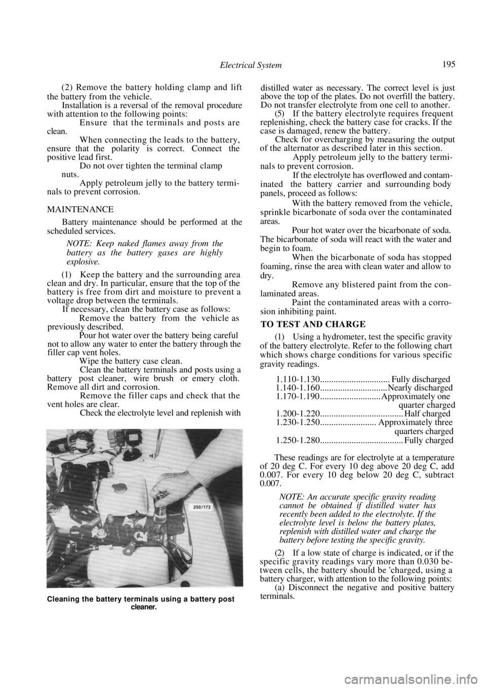
Clean the battery terminals and posts using a
battery post cleaner, wire brush or emery cloth.
Remove all dirt and corrosion.
Remove the filler caps and check that the
vent holes are clear. Check the electrolyte le vel and replenish with distilled water as necessary. The correct level is just
above the top of the plates. Do not overfill the battery.
Do not transfer electrolyte from one cell to another.
(5) If the battery electrolyte requires frequent
replenishing, check the batt ery case for cracks. If the
case is damaged, renew the battery.
Check for overcharging by measuring the output
of the alternator as described later in this section.
Apply petroleum jelly to the battery termi-
nals to prevent corrosion. If the electrolyte has overflowed and contam-
inated the battery carrier and surrounding body
panels, proceed as follows:
With the battery removed from the vehicle,
sprinkle bicarbonate of soda over the contaminated
areas.
Pour hot water over the bicarbonate of soda.
The bicarbonate of soda will react with the water and
begin to foam. When the bicarbonate of soda has stopped
foaming, rinse the area with clean water and allow to
dry. Remove any blistered paint from the con-
laminated areas. Paint the contaminated areas with a corro-
sion inhibiting paint.
TO TEST AND CHARGE
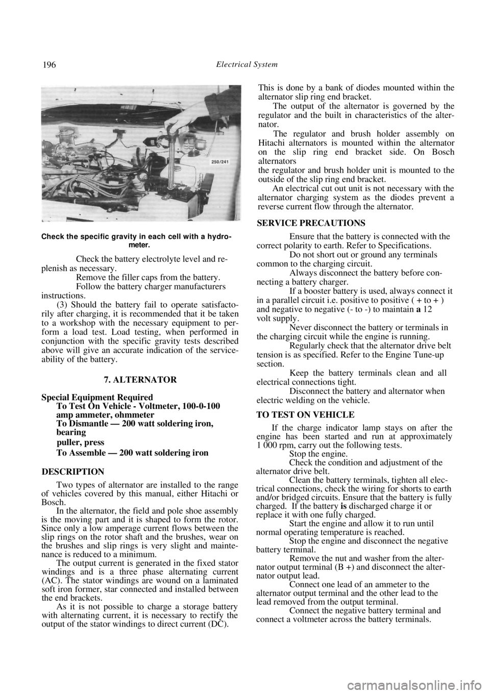
(1) Using a hydrometer, test the specific gravity
of the battery electrolyte. Refer to the following chart
which shows charge conditi ons for various specific
gravity readings.
1.110-1.130............................... Fully discharged
1.140-1.160..............................Nearly discharged
1.170-1.190 ........................... Approximately one
quarter charged
1.200-1.220..................................... Half charged
1.230-1.250......................... Approximately three
quarters charged
1.250-1.280..................................... Fully charged
These readings are for electrolyte at a temperature
of 20 deg C. For every 10 deg above 20 deg C, add
0.007. For every 10 deg below 20 deg C, subtract
0.007.
NOTE: An accurate specific gravity reading
cannot be obtained if distilled water has
recently been added to the electrolyte. If the
electrolyte level is below the battery plates,
replenish with distilled water and charge the
battery before testing the specific gravity.
(2) If a low state of charge is indicated, or if the
specific gravity readings vary more than 0.030 be-
tween cells, the battery s hould be 'charged, using a
battery charger, with attention to the following points:
(a) Disconnect the negati ve and positive battery
terminals.
Cleaning the battery terminals using a battery post
cleaner.
Page 196 of 238
196 Electrical System
Check the specific gravity in each cell with a hydro-
meter.
Check the battery electrolyte level and re-
plenish as necessary. Remove the filler cap s from the battery.
Follow the battery charger manufacturers
instructions. (3) Should the battery fail to operate satisfacto-
rily after charging, it is recommended that it be taken
to a workshop with the necessary equipment to per-
form a load test. Load testing, when performed in
conjunction with the specific gravity tests described
above will give an accurate indication of the service-
ability of the battery.
7. ALTERNATOR
Special Equipment Required
To Test On Vehicle - Voltmeter, 100-0-100
amp ammeter, ohmmeter
To Dismantle — 200 watt soldering iron,
bearing
puller, press
To Assemble — 200 watt soldering iron
DESCRIPTION
Two types of alternator are installed to the range
of vehicles covered by this manual, either Hitachi or
Bosch. In the alternator, the field and pole shoe assembly
is the moving part and it is shaped to form the rotor.
Since only a low amperage current flows between the
slip rings on the rotor shaft and the brushes, wear on
the brushes and slip rings is very slight and mainte-
nance is reduced to a minimum. The output current is generated in the fixed stator
windings and is a three phase alternating current
(AC). The stator windings are wound on a laminated
soft iron former, star connected and installed between
the end brackets. As it is not possible to charge a storage battery
with alternating current, it is necessary to rectify the
output of the stator windings to direct current (DC). This is done by a bank of diodes mounted within the
alternator slip ring end bracket.
The output of the alternator is governed by the
regulator and the built in ch aracteristics of the alter-
nator.
The regulator and brush holder assembly on
Hitachi alternators is mounted within the alternator
on the slip ring end bracket side. On Bosch
alternators
the regulator and brush holder unit is mounted to the
outside of the slip ring end bracket. An electrical cut out unit is not necessary with the
alternator charging system as the diodes prevent a
reverse current flow through the alternator.
SERVICE PRECAUTIONS
Ensure that the battery is connected with the
correct polarity to earth. Refer to Specifications.
Do not short out or ground any terminals
common to the charging circuit. Always disconnect the battery before con-
necting a battery charger.
If a booster battery is used, always connect it
in a parallel circuit i.e. positive to positive ( + to + )
and negative to negative (- to -) to maintain a 12
volt supply. Never disconnect the battery or terminals in
the charging circuit while the engine is running. Regularly check that the alternator drive belt
tension is as specified. Refer to the Engine Tune-up
section.
Keep the battery terminals clean and all
electrical connections tight. Disconnect the battery and alternator when
electric welding on the vehicle.
TO TEST ON VEHICLE If the charge indicator lamp stays on after the
engine has been started and run at approximately
1 000 rpm, carry out the following tests. Stop the engine.
Check the condition and adjustment of the
alternator drive belt. Clean the battery terminals, tighten all elec-
trical connections, check the wiring for shorts to earth
and/or bridged circuits. Ensure that the battery is fully
charged. If the battery is discharged charge it or
replace it with one fully charged. Start the engine and allow it to run until
normal operating temperature is reached.
Stop the engine and disconnect the negative
battery terminal.
Remove the nut and washer from the alter-
nator output terminal (B +) and disconnect the alter-
nator output lead. Connect one lead of an ammeter to the
alternator output terminal and the other lead to the
lead removed from the output terminal. Connect the negative battery terminal and
connect a voltmeter across the battery terminals.
Page 197 of 238
Electrical System 197
Switch on all lamps and allow them to
illuminate for approximately five minutes to reduce
the charge of the battery and to apply a load to the
circuit.
Start the engine and gradually increase the
speed to approximately 2 500 rpm. The reading on
the ammeter should be approximately 75% of the
rated output of the altern ator. See Specifications.
Switch off all the lamps and run the engine at
1 500-2 000 rpm until the indicated charge is below
10 amps. The voltmeter should now read in excess of
13.6 volts.
NOTE: Should the alternator fail to reach
the specific output, the unit will have to be
removed and overhauled or a replacement
unit installed.
Should the voltage reading be above or
below Specifications, the regulator will have
to be renewed.
TO REMOVE AND INSTAL
Disconnect the negative battery terminal.
On 1.8 liter engines, remove the bolt secur-
ing the air cleaner intake duct and remove the air
cleaner intake duct. Drain the radiator by releasing the radiator
drain plug, located at the bottom of the radiator and
allow the coolant level to fall below the thermostat
housing level. NOTE: Refer to the Cooling and Heating
Systems section when refilling the radiator
coolant to its correct l
evel, failure to do so
could result in severe damage to engine
components.
Remove the retaining bolts securing the
thermostat housing, disconnect the hose from the
radiator and remove the thermostat housing and
radiator hose from the vehicle. Using a socket and extension bar, remove the
bolt securing the alternator to the drive belt tensioning
bar located under the alternator. On vehicles not equipped with air condition-
ing, remove the front splash guard from under the
front of the vehicle and remove the bolt securing the
alternator to the drive belt tensioning bar. Loosen the upper mounting bolts, slacken
the alternator drive belt and remove it from the
alternator pulley.
While supporting the alternator, remove the
upper mounting bolts and remove the alternator from
the vehicle. Installation is a reversal of the removal procedure
with attention to the following points:
Do not over tension the drive belt. Refer
to
the Engine Tune-up section for the correct belt
adjusting procedure. Ensure that the wiring and connectors are
securely located on the alternator.
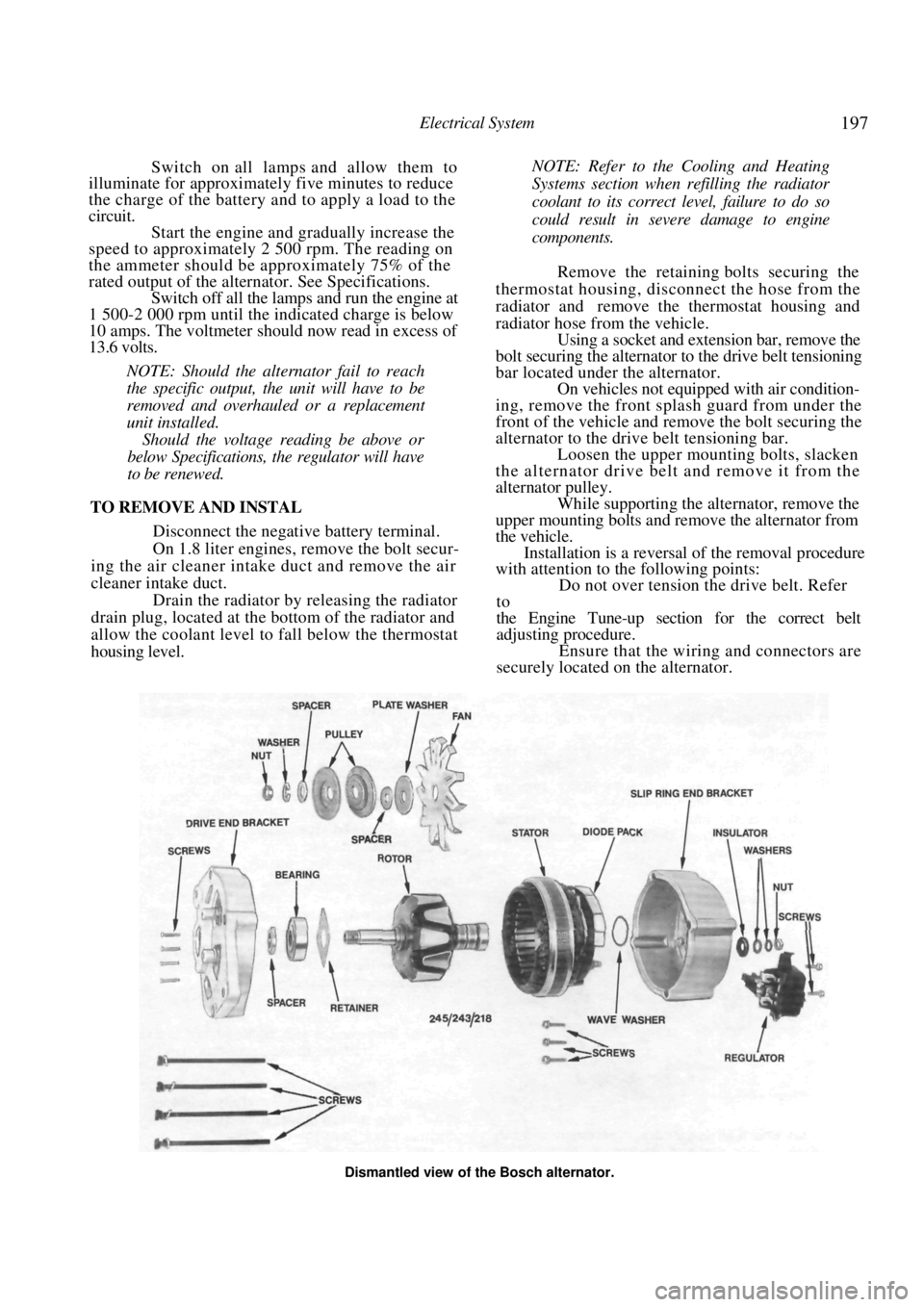
Dismantled view of the Bosch alternator.
Page 198 of 238
198 Electrical System
(3) Replenish the coolant in the radiator. Refer
to the Cooling and Heating Systems section for the
correct procedure.
TO DISMANTLE
Bosch Alternator
Remove the alternator from the vehicle as
previously described.
Scribe a mark across the drive end bracket,
stator and slip ring end bracket to facilitate correct
alignment during assembly. Remove the screws and washers securing the
regulator and brush holder assembly. Withdraw the
regulator and brush holder assembly from the alter-
nator. Remove the long screws securing the drive
end bracket to the slip ring end bracket and withdraw
the drive end bracket, rotor and pulley assembly.
NOTE: Ensure that the wave washer behind
the rotor shaft rear bearing in the slip ring
end bracket is not mislaid.
Holding the rotor in a soft jawed vice,
remove the split drive pulley retaining nut, washer
and spacer from the rotor shaft. Remove the split driv e pulley, spacer, plate
washer and fan from the rotor shaft. Using a suitable pres s and press plates,
support the drive end bracket with the pulley end of
the rotor shaft uppermost a nd carefully press the rotor
shaft from the spacer, bearing and the drive end
bracket.
Remove the spacer and the bearing retainer
plate screws from the drive end bracket. Remove the bearing retainer plate and the
bearing from the drive end bracket. If necessary, using a bearing puller, remove
the rear bearing from the rotor shaft. Remove the nut, spring washer and output
terminal components from the {B + ) terminal on the
outside of the slip ring end bracket.
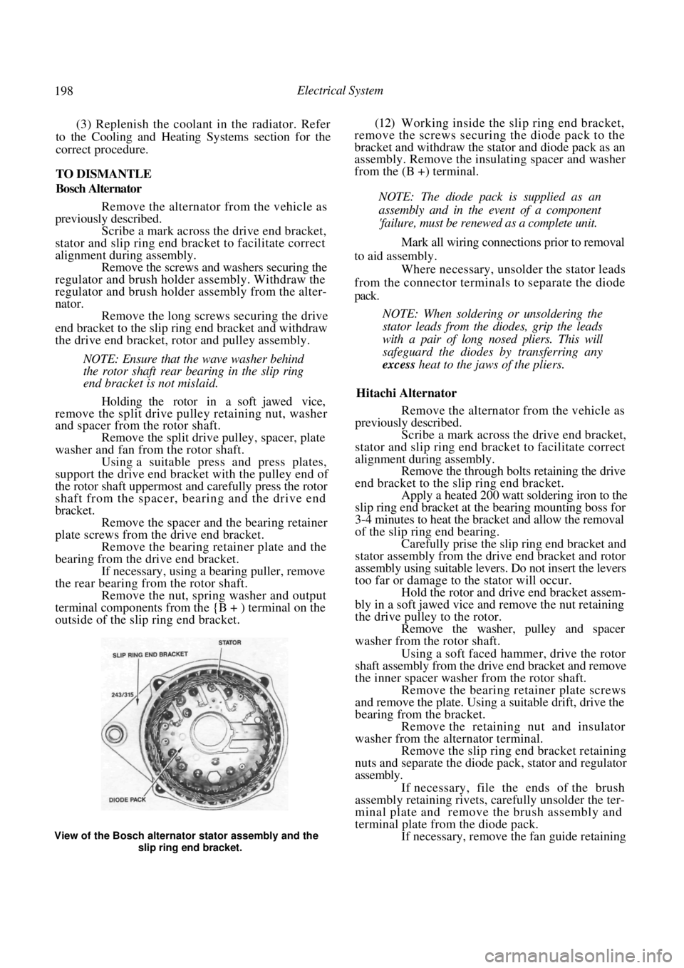
(12) Working inside the slip ring end bracket,
remove the screws securing the diode pack to the
bracket and withdraw the stator and diode pack as an
assembly. Remove the insulating spacer and washer
from the (B +) terminal.
NOTE: The diode pack is supplied as an
assembly and in the event of a component
'failure, must be renewed as a complete unit.
Mark all wiring connections prior to removal
to aid assembly. Where necessary, unsolder the stator leads
from the connector terminals to separate the diode
pack.
NOTE: When soldering or unsoldering the
stator leads from the diodes, grip the leads
with a pair of long nosed pliers. This will
safeguard the diodes by transferring any
excess heat to the jaws of the pliers.
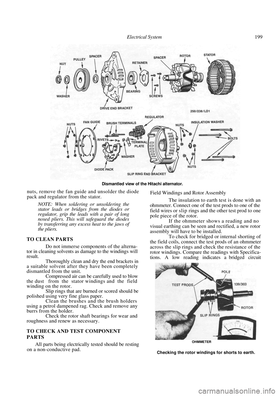
Hitachi Alternator
Remove the alternator from the vehicle as
previously described.
Scribe a mark across the drive end bracket,
stator and slip ring end bracket to facilitate correct
alignment during assembly. Remove the through bolts retaining the drive
end bracket to the slip ring end bracket. Apply a heated 200 watt soldering iron to the
slip ring end bracket at the bearing mounting boss for
3-4 minutes to heat the bracket and allow the removal
of the slip ring end bearing. Carefully prise the slip ring end bracket and
stator assembly from the drive end bracket and rotor
assembly using suitable levers. Do not insert the levers
too far or damage to the stator will occur.
Hold the rotor and driv e end bracket assem-
bly in a soft jawed vice and remove the nut retaining
the drive pulley to the rotor. Remove the washer, pulley and spacer
washer from the rotor shaft.
Using a soft faced hammer, drive the rotor
shaft assembly from the drive end bracket and remove
the inner spacer washer from the rotor shaft.
Remove the bearing retainer plate screws
and remove the plate. Using a suitable drift, drive the
bearing from the bracket. Remove the retaining nut and insulator
washer from the alternator terminal. Remove the slip ring end bracket retaining
nuts and separate the diode pack, stator and regulator
assembly.
If necessary, file the ends of the brush
assembly retaining rivets, caref ully unsolder the ter-
minal plate and remove the brush assembly and
terminal plate from the diode pack. If necessary, remove the fan guide retaining
View of the Bosch alternator stator assembly and the
slip ring end bracket.
Page 199 of 238
Electrical System 199
Dismantled view of the Hitachi alternator.
nuts, remove the fan guide and unsolder the diode
pack and regulator from the stator.
NOTE: When soldering or unsoldering the
stator leads or bridges from the diodes or
regulator, grip the leads with a pair of long
nosed pliers. This will safeguard the diodes
by transferring any excess heat to the jaws of
the pliers.
TO CLEAN PARTS
Do not immerse components of the alterna-
tor in cleaning solvents as damage to the windings will
result. Thoroughly clean and dry the end brackets in
a suitable solvent after they have been completely
dismantled from the unit. Compressed air can be carefully used to blow
the dust from the stator windings and the field
winding on the rotor. Slip rings that are burned or scored should be
polished using very fine glass paper. Clean the brushes and the brush holders
using a petrol dampened rag. Check and remove any
burrs from the holder. Check the rotor shaft bearings for wear and
roughness and renew as necessary.
TO CHECK AND TEST COMPONENT
PARTS
All parts being electrically tested should be resting
on a non-conductive pad.
Field Windings and Rotor Assembly
The insulation to earth test is done with an
ohmmeter. Connect one of the test prods to one of the
field wires or s l i p rings and the other test prod to one
pole piece of the rotor. If the ohmmeter shows a reading and no
visual earthing can be seen and rectified, a new rotor
assembly will have to be installed. To check for bridged or internal shorting of
the field coils, connect the te st prods of an ohmmeter
across the slip rings and check the resistance of the
rotor windings. Compare the readings with Specifica-
tions. A low reading i ndicates a bridged circuit
OHMMETER
Checking the rotor windings for shorts to earth.