light NISSAN PULSAR 1987 Repair Manual
[x] Cancel search | Manufacturer: NISSAN, Model Year: 1987, Model line: PULSAR, Model: NISSAN PULSAR 1987Pages: 238, PDF Size: 28.91 MB
Page 196 of 238
196 Electrical System
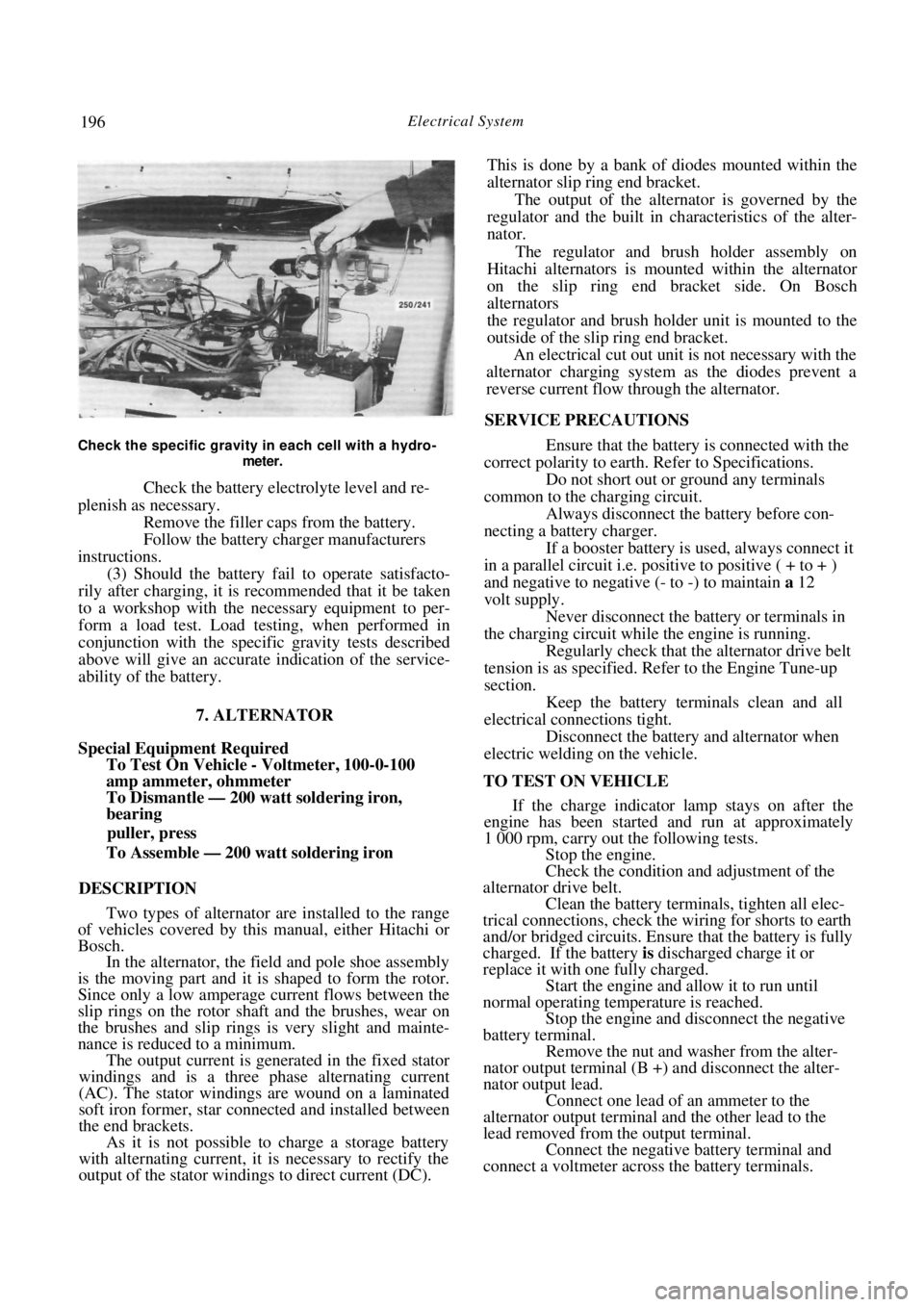
Check the specific gravity in each cell with a hydro-
meter.
Check the battery electrolyte level and re-
plenish as necessary. Remove the filler cap s from the battery.
Follow the battery charger manufacturers
instructions. (3) Should the battery fail to operate satisfacto-
rily after charging, it is recommended that it be taken
to a workshop with the necessary equipment to per-
form a load test. Load testing, when performed in
conjunction with the specific gravity tests described
above will give an accurate indication of the service-
ability of the battery.
7. ALTERNATOR
Special Equipment Required
To Test On Vehicle - Voltmeter, 100-0-100
amp ammeter, ohmmeter
To Dismantle — 200 watt soldering iron,
bearing
puller, press
To Assemble — 200 watt soldering iron
DESCRIPTION
Two types of alternator are installed to the range
of vehicles covered by this manual, either Hitachi or
Bosch. In the alternator, the field and pole shoe assembly
is the moving part and it is shaped to form the rotor.
Since only a low amperage current flows between the
slip rings on the rotor shaft and the brushes, wear on
the brushes and slip rings is very slight and mainte-
nance is reduced to a minimum. The output current is generated in the fixed stator
windings and is a three phase alternating current
(AC). The stator windings are wound on a laminated
soft iron former, star connected and installed between
the end brackets. As it is not possible to charge a storage battery
with alternating current, it is necessary to rectify the
output of the stator windings to direct current (DC). This is done by a bank of diodes mounted within the
alternator slip ring end bracket.
The output of the alternator is governed by the
regulator and the built in ch aracteristics of the alter-
nator.
The regulator and brush holder assembly on
Hitachi alternators is mounted within the alternator
on the slip ring end bracket side. On Bosch
alternators
the regulator and brush holder unit is mounted to the
outside of the slip ring end bracket. An electrical cut out unit is not necessary with the
alternator charging system as the diodes prevent a
reverse current flow through the alternator.
SERVICE PRECAUTIONS
Ensure that the battery is connected with the
correct polarity to earth. Refer to Specifications.
Do not short out or ground any terminals
common to the charging circuit. Always disconnect the battery before con-
necting a battery charger.
If a booster battery is used, always connect it
in a parallel circuit i.e. positive to positive ( + to + )
and negative to negative (- to -) to maintain a 12
volt supply. Never disconnect the battery or terminals in
the charging circuit while the engine is running. Regularly check that the alternator drive belt
tension is as specified. Refer to the Engine Tune-up
section.
Keep the battery terminals clean and all
electrical connections tight. Disconnect the battery and alternator when
electric welding on the vehicle.
TO TEST ON VEHICLE If the charge indicator lamp stays on after the
engine has been started and run at approximately
1 000 rpm, carry out the following tests. Stop the engine.
Check the condition and adjustment of the
alternator drive belt. Clean the battery terminals, tighten all elec-
trical connections, check the wiring for shorts to earth
and/or bridged circuits. Ensure that the battery is fully
charged. If the battery is discharged charge it or
replace it with one fully charged. Start the engine and allow it to run until
normal operating temperature is reached.
Stop the engine and disconnect the negative
battery terminal.
Remove the nut and washer from the alter-
nator output terminal (B +) and disconnect the alter-
nator output lead. Connect one lead of an ammeter to the
alternator output terminal and the other lead to the
lead removed from the output terminal. Connect the negative battery terminal and
connect a voltmeter across the battery terminals.
Page 203 of 238
Electrical System 203
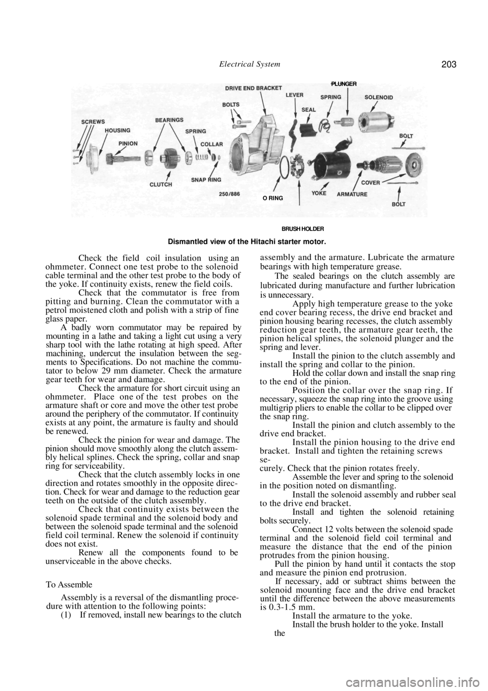
BRUSH HOLDER
Dismantled view of the Hitachi starter motor.
Check the field coil insulation using an
ohmmeter. Connect one test probe to the solenoid
cable terminal and the other test probe to the body of
the yoke. If continuity exists, renew the field coils. Check that the commutator is free from
pitting and burning. Clean the commutator with a
petrol moistened cloth and polish with a strip of fine
glass paper.
A badly worn commutator may be repaired by
mounting in a lathe and taking a light cut using a very
sharp tool with the lathe rotating at high speed. After
machining, undercut the insulation between the seg-
ments to Specifications. Do not machine the commu-
tator to below 29 mm diameter. Check the armature
gear teeth for wear and damage.
Check the armature for short circuit using an
ohmmeter. Place one of the test probes on the
armature shaft or core and move the other test probe
around the periphery of the commutator. If continuity
exists at any point, the armature is faulty and should
be renewed. Check the pinion for wear and damage. The
pinion should move smoothl y along the clutch assem-
bly helical splines. Check the spring, collar and snap
ring for serviceability.
Check that the clutch assembly locks in one
direction and rotates smoothly in the opposite direc-
tion. Check for wear and damage to the reduction gear
teeth on the outside of the clutch assembly.
Check that continuity exists between the
solenoid spade terminal and the solenoid body and
between the solenoid spade terminal and the solenoid
field coil terminal. Renew the solenoid if continuity
does not exist. Renew all the components found to be
unserviceable in the above checks.
To Assemble
Assembly is a reversal of the dismantling proce-
dure with attention to the following points:
(1) If removed, install new bearings to the clutch
assembly and the armature. Lubricate the armature
bearings with high temperature grease.
The sealed bearings on the clutch assembly are
lubricated during manufacture and further lubrication
is unnecessary.
Apply high temperature grease to the yoke
end cover bearing recess, the drive end bracket and
pinion housing bearing recesses, the clutch assembly
reduction gear teeth, the armature gear teeth, the
pinion helical splines, th e solenoid plunger and the
spring and lever. Install the pinion to the clutch assembly and
install the spring and collar to the pinion. Hold the collar down and install the snap ring
to the end of the pinion.
Position the collar over the snap ring. If
necessary, squeeze the snap ring into the groove using
multigrip pliers to enable the collar to be clipped over
the snap ring. Install the pinion and clutch assembly to the
drive end bracket.
Install the pinion housing to the drive end
bracket. Install and tighten the retaining screws
se-
curely. Check that the pinion rotates freely.
Assemble the lever and spring to the solenoid
in the position noted on dismantling.
Install the solenoid assembly and rubber seal
to the drive end bracket.
Install and tighten the solenoid retaining
bolts securely. Connect 12 volts between the solenoid spade
terminal and the solenoid field coil terminal and
measure the distance that the end of the pinion
protrudes from the pinion housing. Pull the pinion by hand until it contacts the stop
and measure the pinion end protrusion.
If necessary, add or subt ract shims between the
solenoid mounting face and the drive end bracket
until the difference between the above measurements
is 0.3-1.5 mm.
Install the armature to the yoke.
Install the brush holder to the yoke. Install
the
PLUNGER
O RING
Page 205 of 238

Electrical System 205
Dismantled view of the brush holder assembly. Bosch
starter motor.
side and the other lead to the negative side. If there is
any indication of leakage the ohmmeter will show a
reading other than infinity. Repair or renew the brush
holder if leakage is evident.
(2) Check the brushes for adequate length.
Brushes should be renewed when their length is below
Specifications. They should be a free sliding fit in the
brush holders.
NOTE: Due to the difficulty involved in
removing and installing the brushes in the
Bosch starter motor, it is recommended that
the brush holder be renewed as an assembly.
(3) Check that the commutator is free from
pitting and burning. Clean with a petrol moistened
cloth and polish with a strip of fine glass paper.
A badly worn commutator may be repaired by
mounting in a lathe, spi nning at high speed, and
taking a light cut with a very sharp tool. After turning,
undercut the insulation between the segments.
(4) Check the armature for short circuit using an
ohmmeter.
Place one of the test lead s on the armature shaft
or core and move the other lead around the circum-
ference of the commutator. If the ohmmeter shows a
reading at any point the armature is faulty and should
be renewed.
Check the drive assembly clutch pinion teeth
for wear, scoring or chipping. A clutch in good
condition should take up the drive in one direction
only. It should rotate easily and smoothly in the
non-drive direction and the assembly should move
smoothly along the armature or drive shaft helical
splines.
Check the armature shaft bushes for wear
and renew as necessary. The old bushes must be
removed and the new ones pressed into the end
brackets using a polished mandrel of the exact diam-
eter of the armature shaft. NOTE: The new bushes must not be reamed
to size, as reaming will impair the porosity
of the bushes and cause early failure. New
bushes should be allowed to stand immersed
in clean light engine oil for one hour before
installation.
To Assemble
Assembly is a reversal of the dismantling proce-
dure with attention to the following points:
Lubricate the helix of the drive shaft lightly
with graphite grease and install the drive assembly
to
the drive shaft. Install the stop collar and snap ring, slide the
stop collar over the snap ring to lock the snap ring in
position.
Lubricate the bushes in both end brackets
sparingly with engine oil. Install the engaging lever and gear set into the
drive end bracket. Install the centre rear bracket and the engag-
ing lever seal into the drive end bracket.
Slide the brush holder assembly into position
on the commutator ensuring that the brush holders
are correctly positioned in the anchor points. Install the commutator end bracket to
the
armature, install the shims and C clip. Check that the armature end float is satisfac-
tory and adjust as necessary using shims of the correct
thickness.
Align the slot in the commutator end bracket
with the cut out on the wiring seal and install the
armature end cover to the commutator end bracket.
Install the cover retaini ng screws but do not tighten.
Ensure that the permanent magnets in the
yoke have not picked up any debris and slide the yoke
over the armature ensuring that the wiring seal locates
correctly in the slot in the yoke.
View showing the planetary gear set. Bosch starter
motor.
Page 206 of 238
206 Electrical System
Install the armature and yoke to the drive end
bracket rotating the drive to align the reduction gears.
Do not use force.
Install the retaining through bolts to the
commutator end bracket and lighten the through bolts
and armature end cover retaining screws securely. Install the solenoid to the drive end bracket,
install the retaining screws and tighten them securely.
Install the brush connector strap and
install
the retaining nut and washer and tighten securely.
9 . IGNITION SYSTEM
The testing and repair procedures for the ignition
system are fully covered in the Fuel and Engine
Management section.
10. STEERING WHEEL
The removal and installation procedures for the
steering wheel and horn pad are fully covered in the
Steering section.
11. SWITCHES AND CONTROLS
IGNITION SWITCH
To Remove and Install
Disconnect the negative battery terminal.
Remove the retaining screws from the steer-
ing column cover. Unclip and separate the upper and lower
steering column covers and remove the upper cover. Release the column adjusting lever and re-
move the lower cover by guiding the column adjusting
lever through the hole in the upper end of the cover.
Disconnect the ignition switch wiring at the
switch. Remove the retaining screw and withdraw
the ignition switch fr om the lock assembly.
Installation is a reversal of the removal procedure.
COMBINATION SWITCH
The combination switch is mounted at the top of
the steering column and incorporates two switches.
The parking lamp, headlamp, headlamp flasher, head-
lamp dipper and turn signal lamps are operated by a
lever on the right hand side. A lever on the left hand
side operates the windscreen washer and wiper switch.
These switches can be re newed without removing
the combination switch.
To Remove and Install Switches
Remove the retaining screws from the steer-
ing column cover.
Unclip and separate the upper and lower
steering column covers and remove the upper cover.
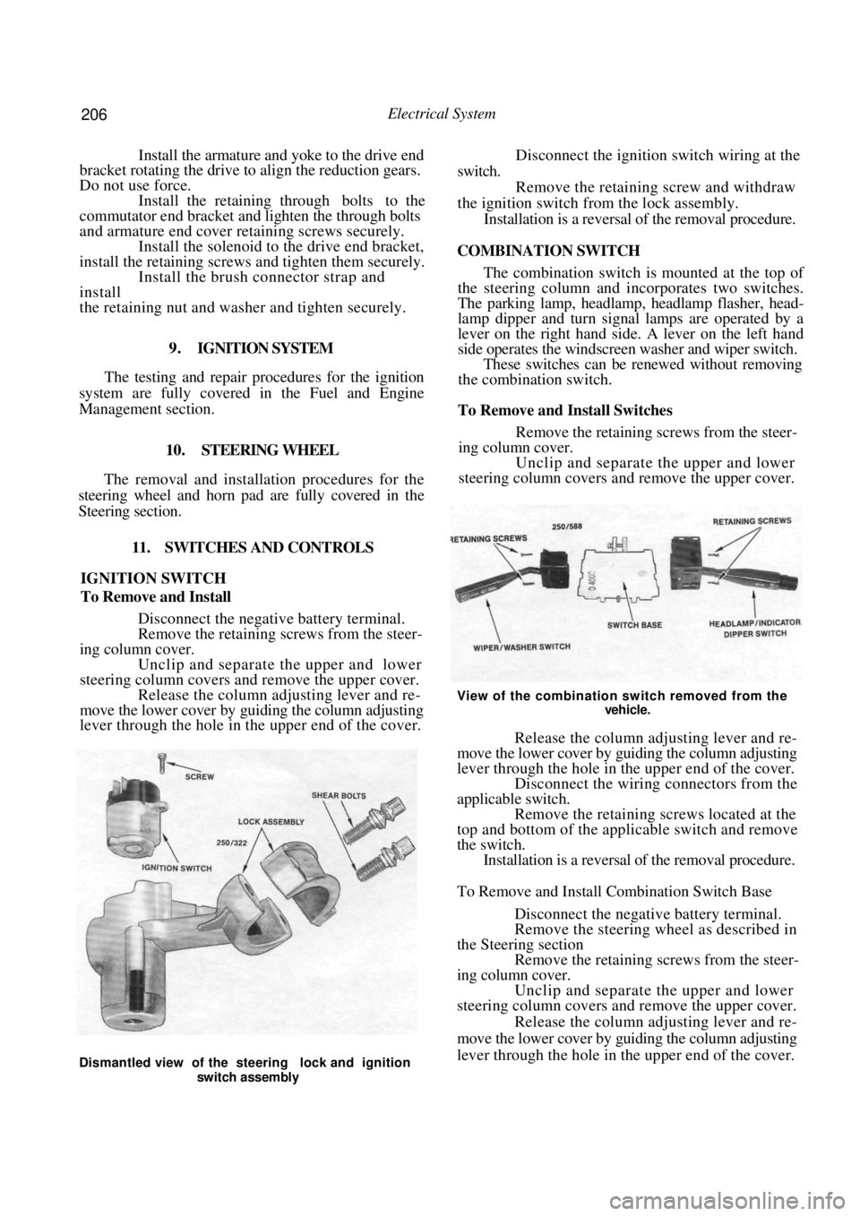
View of the combination switch removed from the
vehicle.
Release the column adjusting lever and re-
move the lower cover by guiding the column adjusting
lever through the hole in the upper end of the cover. Disconnect the wiring connectors from the
applicable switch. Remove the retaining screws located at the
top and bottom of the applicable switch and remove
the switch. Installation is a reversal of the removal procedure.
To Remove and Install Combination Switch Base
Disconnect the negative battery terminal.
Remove the steering wheel as described in
the Steering section Remove the retaining screws from the steer-
ing column cover. Unclip and separate the upper and lower
steering column covers and remove the upper cover.
Release the column adjusting lever and re-
move the lower cover by guiding the column adjusting
lever through the hole in the upper end of the cover.
Dismantled view of the steering lock and ignition
switch assembly
Page 210 of 238
210 Electrical System
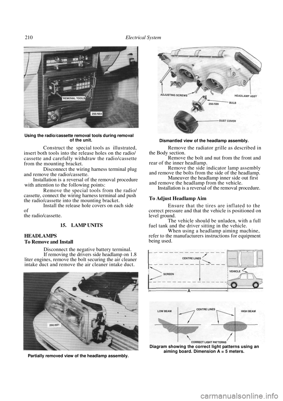
Using the radio/cassette removal tools during removal of the unit.
Construct the special tools as illustrated,
insert both tools into the release holes on the radio/
cassette and carefully withdraw the radio/cassette
from the mounting bracket.
Disconnect the wiring harness terminal plug
and remove the radio/cassette.
Installation is a reversal of the removal procedure
with attention to the following points:
Remove the special tools from the radio/
cassette, connect the wiring harness terminal and push
the radio/cassette into the mounting bracket. Install the release hole covers on each side
of
the radio/cassette.
15. LAMP UNITS
HEADLAMPS
To Remove and Install
Disconnect the negative battery terminal.
If removing the drivers side headlamp on 1.8
liter engines, remove the bo lt securing the air cleaner
intake duct and remove the air cleaner intake duct.
Dismantled view of the headlamp assembly.
Remove the radiator grille as described in
the Body section. Remove the bolt and nut from the front and
rear of the inner headlamp. Remove the side indicator lamp assembly
and remove the bolts from the side of the headlamp.
Maneuver the headlamp inner side out first
and remove the headlamp from the vehicle. Installation is a reversal of the removal procedure.
To Adjust Headlamp Aim
Ensure that the tires are inflated to the
correct pressure and that the vehicle is positioned on
level ground.
The vehicle should be unladen, with a full
fuel tank and the driver sitting in the vehicle. When using a headlamp aiming machine,
refer to the manufacturers instructions for equipment
being used.
Partially removed view of the headlamp assembly. Diagram showing the correct light patterns using an
aiming board. Dimension A = 5 meters.
Page 219 of 238
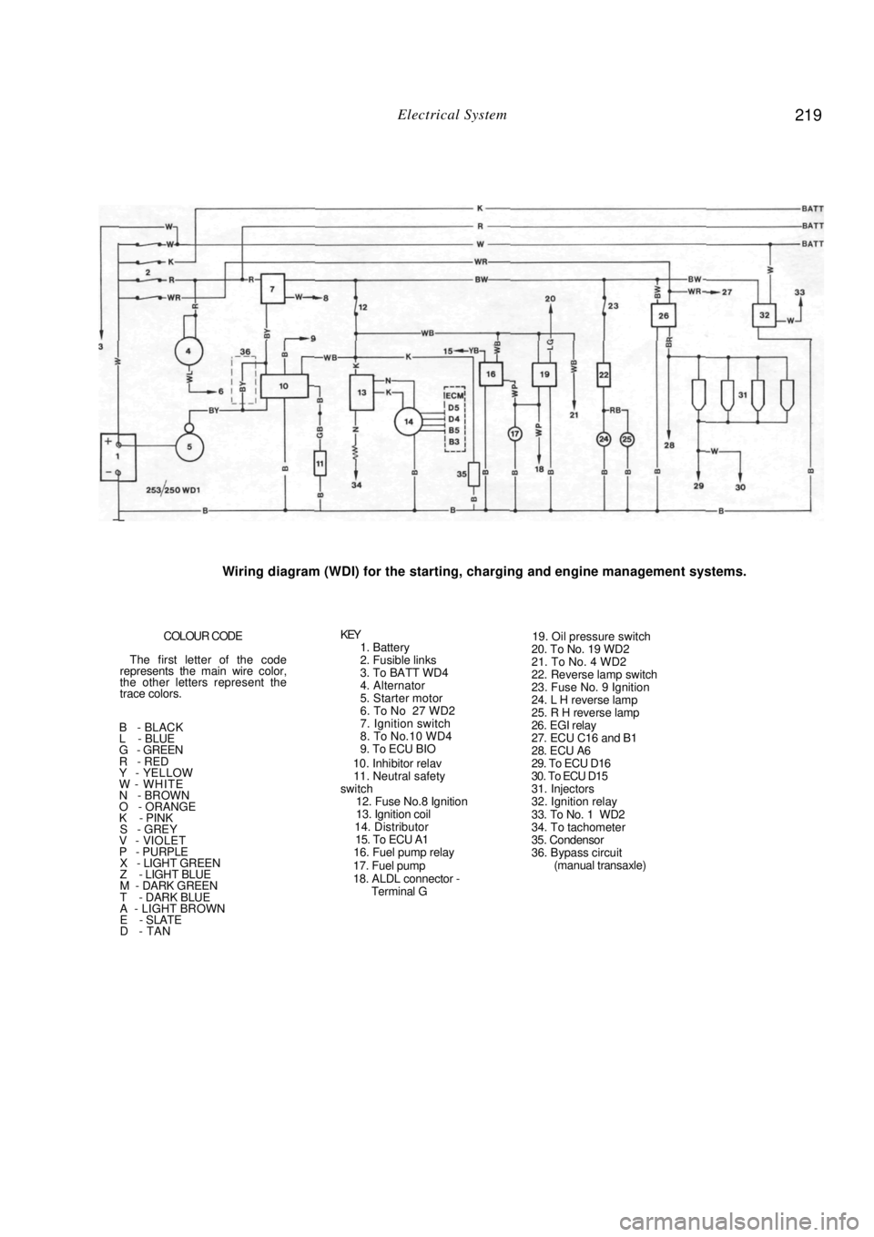
Electrical System 219
Wiring diagram (WDI) for the starting, charging and engine management systems.
COLOUR CODE
The first letter of the code
represents the main wire color,
the other letters represent the
trace colors.
B - BLACK
L - BLUE
G - GREEN
R - RED
Y - YELLOW
W - WHITE
N - BROWN
O - ORANGE
K - PINK
S - GREY V - VIOLET
P - PURPLE X - LIGHT GREEN
Z - LIGHT BLUE
M - DARK GREEN
T - DARK BLUE
A - LIGHT BROWN
E - SLATE
D - TAN
KEY 1. Battery
2. Fusible links
3. To BATT WD4
4. Alternator
5. Starter motor
6. To No 27 WD2
7. Ignition switch
8. To No.10 WD4
9. To ECU BIO
10. Inhibitor relav
11. Neutral safety
switch
12. Fuse No.8 Ignition
13. Ignition coil
14. Distributor
15. To ECU A1
16. Fuel pump relay
17. Fuel pump
18. ALDL connector - Terminal G
19. Oil pressure switch
20. To No. 19 WD2
21. To No. 4 WD2
22. Reverse lamp switch
23. Fuse No. 9 Ignition
24. L H reverse lamp
25. R H reverse lamp
26. EGI relay
27. ECU C16 and B1
28. ECU A6
29. To ECU D16
30. To ECU D15
31. Injectors
32. Ignition relay
33. To No. 1 WD2
34. To tachometer
35. Condensor
36. Bypass circuit (manual transaxle)
Page 220 of 238
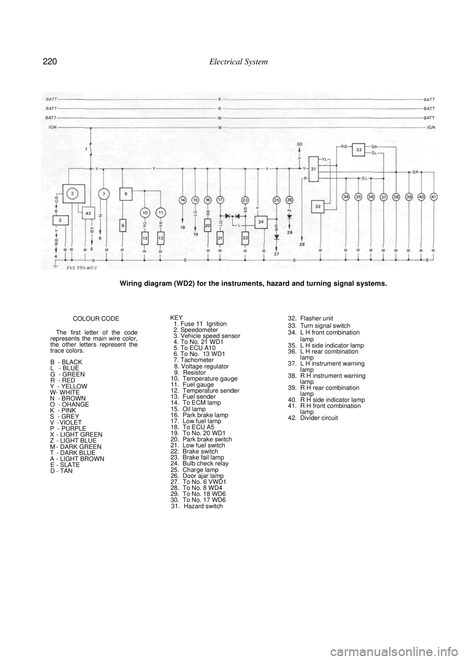
220 Electrical System
Wiring diagram (WD2) for the instruments, hazard and turning signal systems.
COLOUR CODE
The first letter of the code
represents the main wire color,
the other letters represent the
trace colors.
B - BLACK
L - BLUE
G - GREEN
R - RED
Y - YELLOW
W- WHITE
N - BROWN
O - OHANGE
K - PINK
S - GREY V -VIOLET
P - PURPLE X - LIGHT GREEN Z - LIGHT BLUE M - DARK GREEN T - DARK BLUE A - LIGHT BROWN E - SLATE D - TAN
KEY 1. Fuse 11 Ignition
2. Speedometer
3. Vehicle speed sensor
4. To No. 21 WD1
5. To ECU A10
6. To No. 13 WD1
7. Tachometer
8. Voltage regulator
9. Resistor
10. Temperature gauge
11. Fuel gauge
12. Temperature sender
13. Fuel sender
14. To ECM lamp
15. Oil lamp
16. Park brake lamp
17. Low fuel lamp
18. To ECU A5
19. To No. 20 WD1
20. Park brake switch
21. Low fuel switch
22. Brake switch
23. Brake fail lamp
24. Bulb check relay
25. Charge lamp
26. Door ajar lamp
27. To No. 6 VWD1
28. To No. 8 WD4
29. To No. 18 WD6
30. To No. 17 WD6 31. Hazard switch
32. Flasher unit
33. Turn signal switch
34. L H front combination
lamp
35. L H side indicator lamp
36. L H rear combination lamp
37. L H instrument warning
lamp
38. R H instrument warning lamp
39. R H rear combination lamp
40. R H side indicator lamp
41. R H front combination lamp
42. Divider circuit
Page 221 of 238
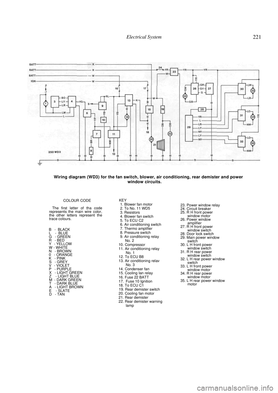
Electrical System 221
Wiring diagram (WD3) for the fan switch, blower, air conditioning, rear demister and power
window circuits.
COLOUR CODE
The first letter of tha code
represents the main wire color,
the other letters represent the
trace colours.
B - BLACK
L - BLUE
G - GREEN
R - BED
Y - YELLOW
W - WHITE
N - BROWN
0 - ORANGE
K - PINK
S - GREY
V - VIOLET
P - PURPLE
X - LIGHT GREEN
Z - LIGHT BLUE
M - DARK GREEN
T - DARK BLUE
A - LIGHT BROWN
E - SLATE
D - TAN KEY
1. Blower fan motor
2. To No. 11 WD5
3. Resistors
4. Blower fan switch
5. To ECU C2
6. Air conditioning switch
7. Thermo amplifier
8. Pressure switch
9. Air conditioning relay No. 2
10. Compressor
11. Air conditioning relay No. 1
12. To ECU B8
13. Air conditioning relav No. 3
14. Condenser fan
15. Cooling Ian relay
16. Fuse 22 BATT
17. Fuse 10 Ignition
18. To ECU C1
19. Rear demister switch
20. Cooling fan motor
21. Rear demister
22. Rear demister warning lamp
23. Power window relay
24. Circuit breaker
25. R H front power
window motor
26. Power window amplifier
27. R H front power window switch
28. Door lock switch
29. Main power window switch
30. L H front power
window switch
31. R H rear power window switch
32. L H rear power window switch
33. L H front power
window motor
34. R H rear power window motor
35. L H rear power window motor
Page 222 of 238

222 Electrical System
Wiring diagram (WD4) for the horn, audio, front wiper/washer and rear wiper/washer circuits.
COLOUR CODE
The first letter of the code
represents the main wire color.
the other letters represent the
trace colors.
B - BLACK
L - BLUE
G - GREEN
R - RED
Y - YELLOW
W - WHITE
N - BROWN
O - ORANGE
K - PINK
S - GREY V - VIOLET
P - PURPLE X - LIGHT GREEN
Z - LIGHT BLUE
M - DARK GREEN
T - DARK BLUE
A - LIGHT BROWN
E - SLATE
D - TAN
KEY 1. Fuse No. 18 Batt
2. Horn relay
3. Horn switch
4. Horn
5. Stop lamp switch
6. L H stop lamp
7. R H stop lamp
8. To No. 28 WD2
9. To No. 14 WD6
10. To No. 8 WD1
11. Radio cassette and clock
12. L H front speaker
13. L H rear speaker
14. R H front speaker
15. R H rear speaker
16. Fuse No. 19 Batt
17. Fuse No. 20 Batt
18. Fuse No. 6 ACC
19. Rear washer motor
20. Rear wiper/washer
motor
21. Rear wiper motor
22. Fuse No. 7 ACC
23. Front wiper motor
24. Front washer motor
25. Intermittent wiper relay
26. Front wiper/washer
switch
27. Variable intermittent
switch
Page 223 of 238

Electrical System 223
Wiring diagram (WD5) for the mirrors, cigarette lighter and door lock circuits.
COLOUR CODE
The first letter of the code
represents the main wire color,
the other letters represent the
trace colors.
B - BLACK
L - BLUE
G - GREEN
R - RED
Y - YELLOW
W - WHITE
N - BROWN
O - ORANGE
K - PINK
S - GREY V - VIOLET
P - PURPLE X - LIGHT GREEN
Z - LIGHT BLUE
M - DARK GREEN
T - DARK BLUE
A - LIGHT BROWN
E - SLATE
D - TAN
KEY 1. Accessories relay
2. R H power mirror 3. L H power mirror
4. Power mirror switch
5. Fuse No. 3 ACC
6. Fuse No. 4 ACC
7. Fuse No. 5 ACC
8. Fuse No 21 B
9. Cigarette lighter
10. To No. 13 WD6
11. To No. 2 WD3
12. Door lock timer
13. Front door lock switch
14. Key lock switch
15. Door lock switch
16. L H front door lock solenoid
17. R H rear door lock solenoid
18. L H rear door lock
solenoid