light NISSAN PULSAR 1987 Owner's Manual
[x] Cancel search | Manufacturer: NISSAN, Model Year: 1987, Model line: PULSAR, Model: NISSAN PULSAR 1987Pages: 238, PDF Size: 28.91 MB
Page 77 of 238
Cooling and Heating Systems 77
These openings are plugged with welch plugs. The
plugs may have to be renewed when cleaning the
engine water jackets or when defective due to corro-
sion.
TO RENEW
NOTE: If a welch plug is found to be
corroded it is good policy to renew all the
welch plugs.
(1) Drain the radiator and cylinder block.
(2) Remove the necessary engine components or
accessories to gain ampl e working space around the
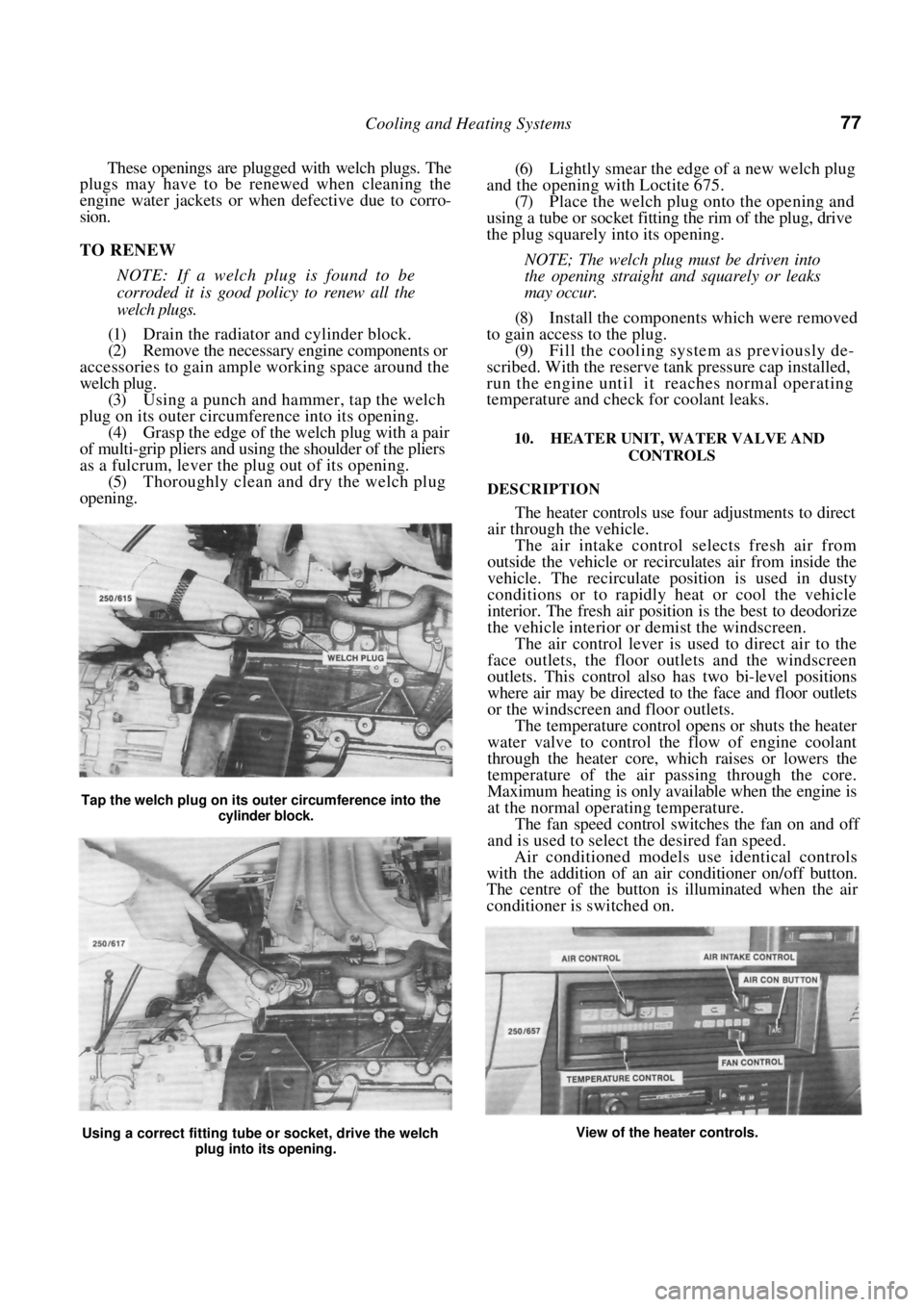
welch plug. (3) Using a punch and hammer, tap the welch
plug on its outer circumference into its opening. (4) Grasp the edge of the welch plug with a pair
of multi-grip pliers and using the shoulder of the pliers
as a fulcrum, lever the plug out of its opening. (5) Thoroughly clean and dry the welch plug
opening.
(6) Lightly smear the edge of a new welch plug
and the opening with Loctite 675. (7) Place the welch plug onto the opening and
using a tube or socket fitting the rim of the plug, drive
the plug squarely into its opening.
NOTE; The welch plug must be driven into
the opening straight and squarely or leaks
may occur.
(8) Install the components which were removed
to gain access to the plug. (9) Fill the cooling system as previously de-
scribed. With the reserve tank pressure cap installed,
run the engine until it reaches normal operating
temperature and check for coolant leaks.
10. HEATER UNIT, WATER VALVE AND
CONTROLS
DESCRIPTION
The heater controls use four adjustments to direct
air through the vehicle.
The air intake control selects fresh air from
outside the vehicle or recirculates air from inside the
vehicle. The recirculate position is used in dusty
conditions or to rapidly heat or cool the vehicle
interior. The fresh air positi on is the best to deodorize
the vehicle interior or demist the windscreen.
The air control lever is used to direct air to the
face outlets, the floor outle ts and the windscreen
outlets. This control also has two bi-level positions
where air may be directed to the face and floor outlets
or the windscreen and floor outlets.
The temperature control opens or shuts the heater
water valve to control the flow of engine coolant
through the heater core, which raises or lowers the
temperature of the air passing through the core.
Maximum heating is only available when the engine is
at the normal operating temperature.
The fan speed control switches the fan on and off
and is used to select the desired fan speed.
Air conditioned models use identical controls
with the addition of an air conditioner on/off button.
The centre of the button is illuminated when the air
conditioner is switched on.
Tap the welch plug on its ou ter circumference into the
cylinder block.
Using a correct fitting tube or socket, drive the welch
plug into its opening. View of the heater controls.
Page 78 of 238
78 Cooling and Heating Systems
The air conditioner operates only when the engine
is running as the compressor is belt driven from the
engine.
Operating the air conditioner with the tempera-
ture control raised to a hot setting will produce
dehumidified hot air which is particularly useful for
demisting the vehicle glass.
Maximum cooling is achieved by operating the air
conditioner with the temperature control lowered
fully to the coldest setting . Operate the fan at high
speed when using the coldest temperature setting to
avoid forming ice on the evaporator.
TO REMOVE AND INSTAL HEATER UNIT
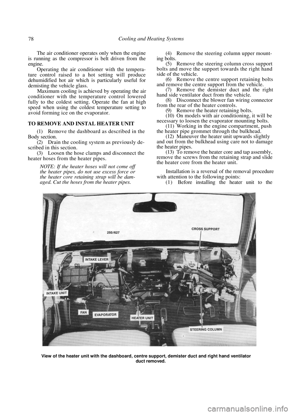
(1) Remove the dashboard as described in the
Body section. (2) Drain the cooling system as previously de-
scribed in this section. (3) Loosen the hose clamps and disconnect the
heater hoses from the heater pipes.
NOTE: If the heater hos es will not come off
the heater pipes, do not use excess force or
the heater core retaining strap will be dam-
aged. Cut the hoses from the heater pipes.
(4) Remove the steering column upper mount-
ing bolts. (5) Remove the steering column cross support
bolts and move the support towards the right hand
side of the vehicle. (6) Remove the centre support retaining bolts
and remove the centre support from the vehicle.
(7) Remove the demister duct and the right
hand side ventilator duct from the vehicle. (8) Disconnect the blower fan wiring connector
from the rear of the heater controls. (9) Remove the heater retaining bolts.
(10) On models with air conditioning, it will be
necessary to loosen the evaporator mounting bolts. (11) Working in the engine compartment, push
the heater pipe grommet through the bulkhead. (12) Maneuver the heater unit upwards slightly
and out from the bulkhead using care not to damage
the heater pipes. (13) To remove the heater core and tap assembly,
remove the screws from the retaining strap and slide
the heater core from the heater unit.
Installation is a reversal of the removal procedure
with attention to the following points:
(1 ) Before installing the heater unit to the
View of the heater unit with the dashboard, centr e support, demister duct and right hand ventilator
duct removed.
Page 79 of 238
Cooling and Heating Systems 79
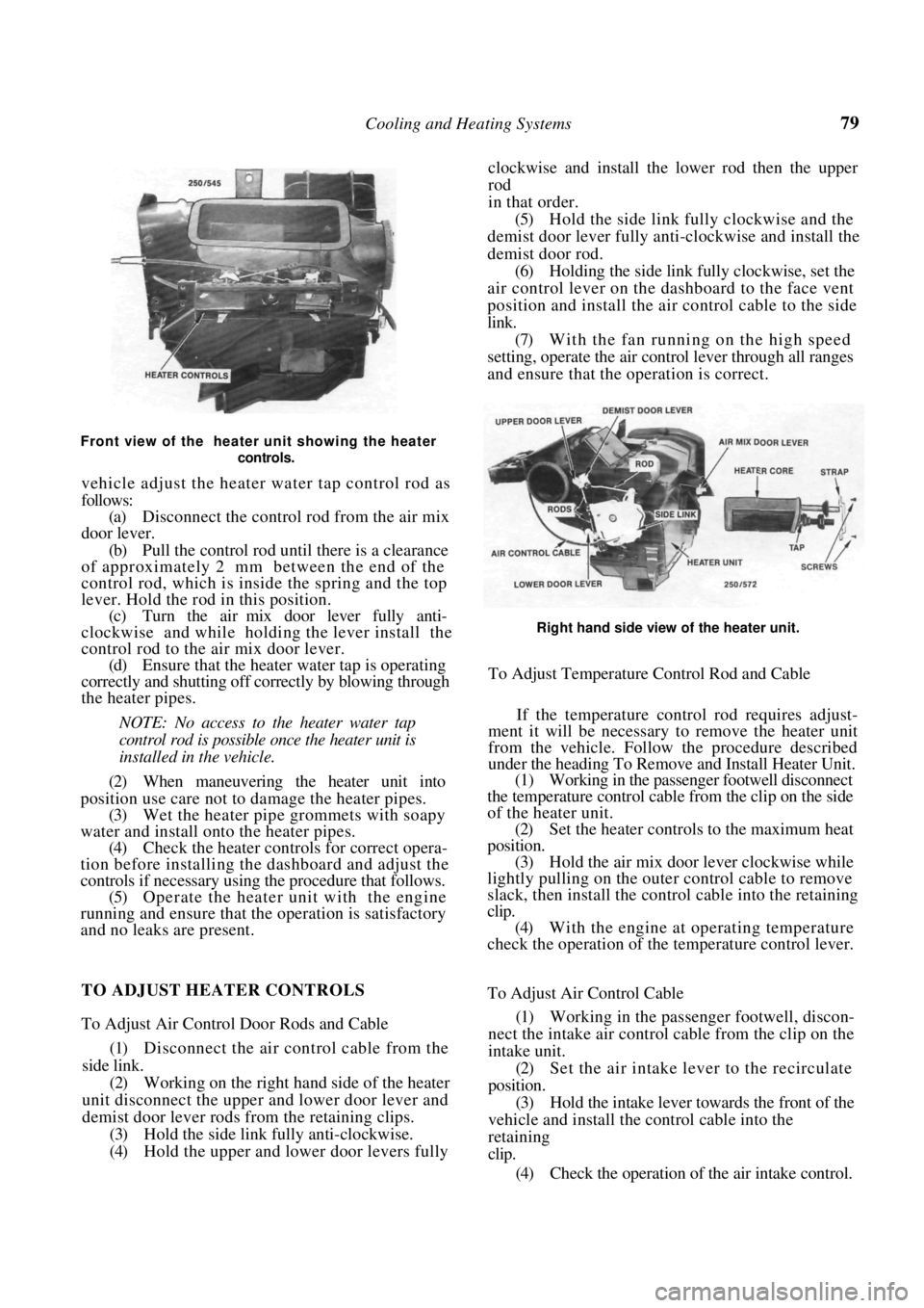
Front view of the heater unit showing the heater controls.
vehicle adjust the heater water tap control rod as
follows:
(a) Disconnect the control rod from the air mix
door lever.
(b) Pull the control rod un til there is a clearance
of approximately 2 mm between the end of the
control rod, which is inside the spring and the top
lever. Hold the rod in this position.
(c) Turn the air mix door lever fully anti-
clockwise and while holding the lever install the
control rod to the air mix door lever. (d) Ensure that the heater water tap is operating
correctly and shutting off correctly by blowing through
the heater pipes.
NOTE: No access to the heater water tap
control rod is possible once the heater unit is
installed in the vehicle.
(2) When maneuvering the heater unit into
position use care not to damage the heater pipes. (3) Wet the heater pipe grommets with soapy
water and install onto the heater pipes. (4) Check the heater controls for correct opera-
tion before installing the dashboard and adjust the
controls if necessary using the procedure that follows. (5) Operate the heater unit with the engine
running and ensure that the operation is satisfactory
and no leaks are present. clockwise and install the lower rod then the upper
rod
in that order.
(5)
Hold the side link fully clockwise and the
demist door lever fully anti-clockwise and install the
demist door rod. (6) Holding the side link fully clockwise, set the
air control lever on the dashboard to the face vent
position and install the air control cable to the side
link. (7) With the fan running on the high speed
setting, operate the air cont rol lever through all ranges
and ensure that the operation is correct.
Right hand side view of the heater unit.
To Adjust Temperature Control Rod and Cable
If the temperature control rod requires adjust-
ment it will be necessary to remove the heater unit
from the vehicle. Follow the procedure described
under the heading To Remove and Install Heater Unit.
(1) Working in the passenger footwell disconnect
the temperature control cable from the clip on the side
of the heater unit. (2) Set the heater controls to the maximum heat
position. (3) Hold the air mix door lever clockwise while
lightly pulling on the outer control cable to remove
slack, then install the control cable into the retaining
clip.
(4) With the engine at operating temperature
check the operation of the temperature control lever.
TO ADJUST HEATER CONTROLS
To Adjust Air Control Door Rods and Cable
(1) Disconnect the air control cable from the
side link. (2) Working on the right hand side of the heater
unit disconnect the upper and lower door lever and
demist door lever rods from the retaining clips.
(3) Hold the side link fully anti-clockwise.
(4) Hold the upper and lower door levers fully To Adjust Air Control Cable
(1)
Working in the passeng er footwell, discon-
nect the intake air control cable from the clip on the
intake unit. (2) Set the air intake lever to the recirculate
position. (3) Hold the intake lever to wards the front of the
vehicle and install the control cable into the
retaining
clip.
(4) Check the operation of the air intake control.
Page 86 of 238
86 Fuel and Engine Management
other. The fuel pressure is maintained at a constant
pressure relevant to the manifold vacuum. A dispos-
able paper element fuel filter is mounted on the engine
bulkhead.
The amount of fuel injected is relevant to the time
the injector remains open. The basic time the injector
remains open is governed by the control unit which
uses information from the various sensors to give
optimum engine efficiency for given conditions.
The idle air control (IAC) valve controls the fast
idle speed during engine warm up and maintains the
basic idle speed at a set value by compensating for
loads such as air conditioning or the selection of Drive
on automatic transaxle models.
The throttle body assembly is mounted to the
inlet manifold and controls the amount of air entering
the engine by the action of the throttle valve.
Efficient operation of the EFI system depends on
accurate signals being receiv ed by the control unit and
controlled air flow beyond the throttle valve. There-
fore it is essential that all air, fuel and electrical
connections be clean and tight.
3. SERVICE PRECAUTIONS AND
PROCEDURES
Electronic ignition systems can produce danger-
ously high voltages in both the primary and secondary
circuits. For this reason, extreme care must be taken
when working on or near the ignition system.
Do not start the engine if the battery terminals are
not clean and tight.
Do not use the fast charge or boost settings on a
battery charger to start the engine.
Do not disconnect the battery terminals while the
engine is running.
Disconnect the battery terminals before charging
the battery.
Disconnect the negative ba ttery terminal before
working on the engine management system.
Do not subject the control unit to temperatures
above 80 deg C.
Ensure that all wiring connectors are clean and
tight.
Disconnect the battery terminals and the control
unit wiring connectors before attempting any welding
operations.
Do not direct a steam cleaning or pressure
washing nozzle at engine management components
when cleaning the engine.
Ensure that the ignition is Off prior to disconnect-
ing the battery terminals, fusible links or the control
unit wiring connectors.
TO CONNECT ELECTRICAL TEST
EQUIPMENT
NOTE: Some types of tachometers, timing
lights and ignition system analysers are not
compatible with this engine management
system and may result in incorrect readings.
It is therefore recommended that the man-
ufacturer of the lest equipment be consulted
before proceeding to use the equipment.
If a test procedure requires the use of a
test lamp or voltmeter, ensure that only the
specified instrument is used to prevent mis-
leading diagnosis.
MULTIMETER
It is essential that in all tests where voltage or
resistance is to be measur ed, a digital display multi-
meter with a minimum 10 megohms impedance be
used.
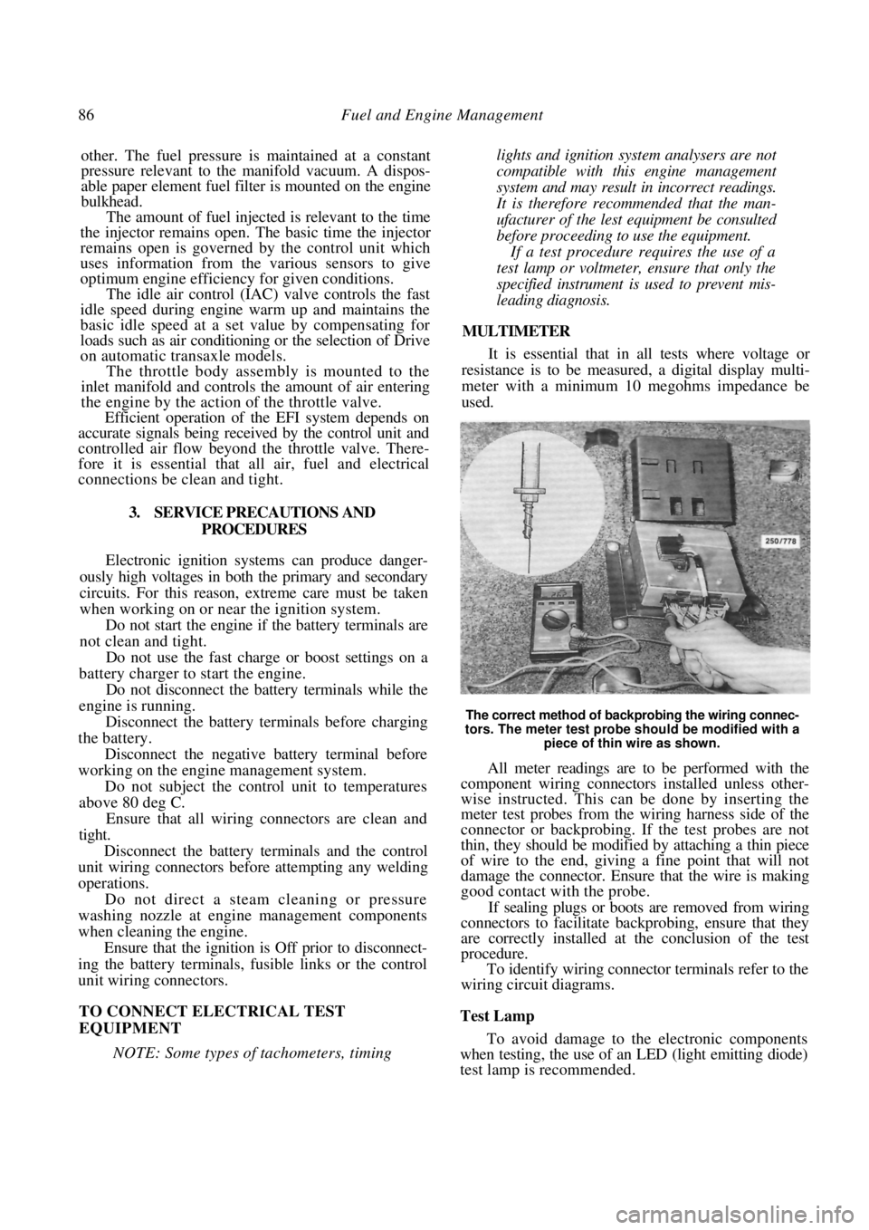
The correct method of backprobing the wiring connec-
tors. The meter test probe should be modified with a piece of thin wire as shown.
All meter readings are to be performed with the
component wiring connectors installed unless other-
wise instructed. This can be done by inserting the
meter test probes from the wiring harness side of the
connector or backprobing. If the test probes are not
thin, they should be modified by attaching a thin piece
of wire to the end, giving a fine point that will not
damage the connector. Ensure that the wire is making
good contact with the probe.
If sealing plugs or boots are removed from wiring
connectors to facilitate bac kprobing, ensure that they
are correctly installed at the conclusion of the test
procedure.
To identify wiring connector terminals refer to the
wiring circuit diagrams.
Test Lamp
To avoid damage to the electronic components
when testing, the use of an LED (light emitting diode)
test lamp is recommended.
Page 89 of 238
Fuel and Engine Management 89
The procedure for fabricating an LED test lamp is
fully described in the El ectrical System section.
If a conventional test lamp with a filament type
bulb is to be used, ensure that the current draw of the
test lamp does not exceed 0.3 amp to avoid damage to
the electronic components.
To check the current draw connect an accurate
ammeter, such as the multimeter described previ-
ously, in series with the test lamp and a battery.
If the ammeter reads less than 0.3 amp the test
lamp is suitable.
Tachometer
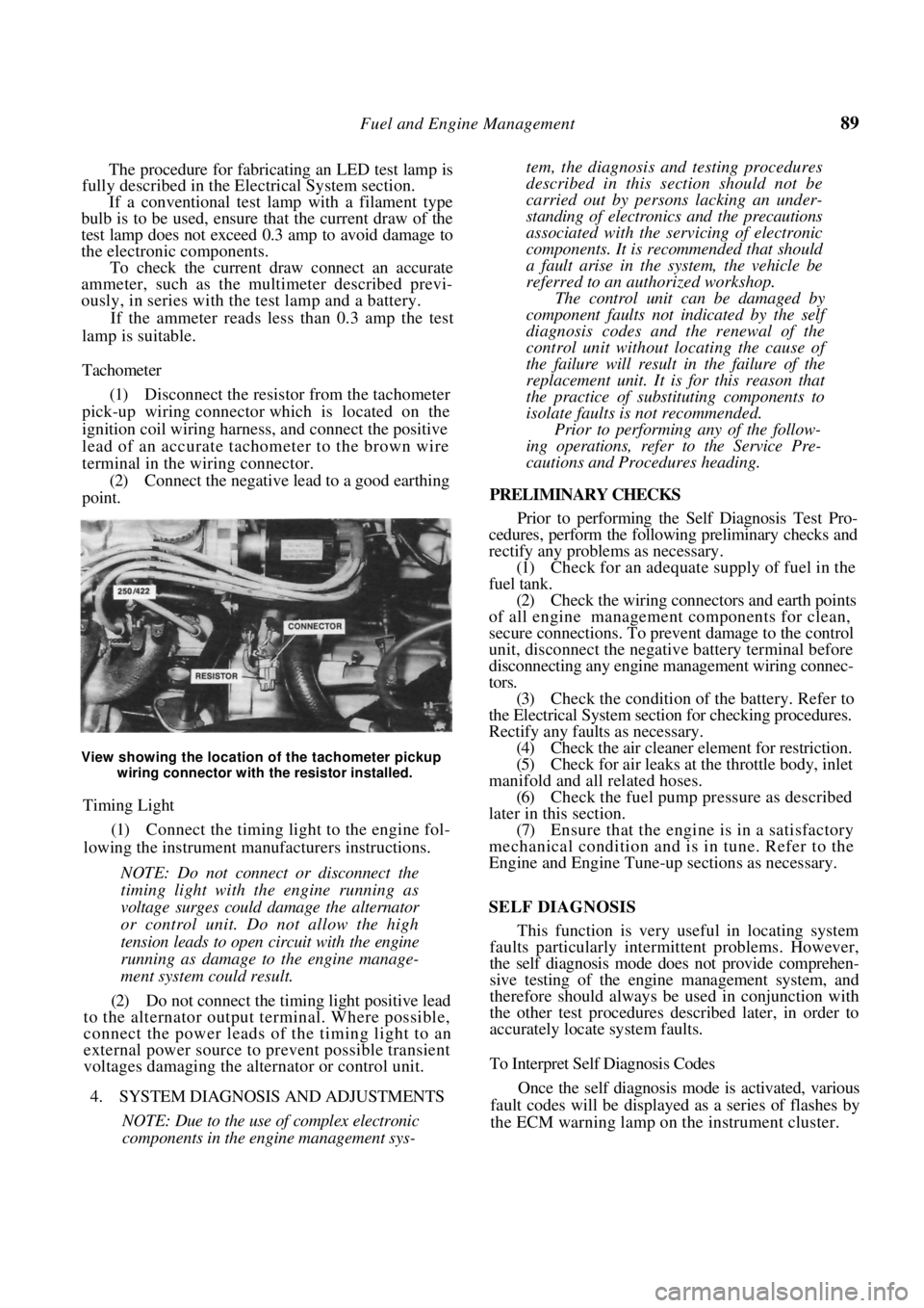
(1) Disconnect the resistor from the tachometer
pick-up wiring connector which is located on the
ignition coil wiring harness, and connect the positive
lead of an accurate tachometer to the brown wire
terminal in the wiring connector. (2) Connect the negative lead to a good earthing
point.
View showing the location of the tachometer pickup
wiring connector with the resistor installed.
Timing Light
(1) Connect the timing light to the engine fol-
lowing the instrument manufacturers instructions.
NOTE: Do not connect or disconnect the
timing light with the engine running as
voltage surges could damage the alternator
or control unit. Do not allow the high
tension leads to open circuit with the engine
running as damage to the engine manage-
ment system could result.
(2) Do not connect the timing light positive lead
to the alternator output terminal. Where possible,
connect the power leads of the timing light to an
external power source to prevent possible transient
voltages damaging the alternator or control unit.
4. SYSTEM DIAGNOSIS AND ADJUSTMENTS
NOTE: Due to the use of complex electronic
components in the engine management sys-
tem, the diagnosis and testing procedures
described in this section should not be
carried out by persons lacking an under-
standing of electronics and the precautions
associated with the servicing of electronic
components. It is rec ommended that should
a fault arise in the system, the vehicle be
referred to an authorized workshop.
The control unit can be damaged by
component faults not indicated by the self
diagnosis codes and the renewal of the
control unit without lo cating the cause of
the failure will result in the failure of the
replacement unit. It is for this reason that
the practice of substituting components to
isolate faults is not recommended.
Prior to performing any of the follow-
ing operations, refer to the Service Pre-
cautions and Procedures heading.
PRELIMINARY CHECKS
Prior to performing the Self Diagnosis Test Pro-
cedures, perform the following preliminary checks and
rectify any problems as necessary.
(1) Check for an adequate supply of fuel in the
fuel tank. (2) Check the wiring connectors and earth points
of all engine management components for clean,
secure connections. To prevent damage to the control
unit, disconnect the negative battery terminal before
disconnecting any engine ma nagement wiring connec-
tors. (3) Check the condition of the battery. Refer to
the Electrical System sectio n for checking procedures.
Rectify any faults as necessary. (4) Check the air cleaner element for restriction.
(5) Check for air leaks at the throttle body, inlet
manifold and all related hoses. (6) Check the fuel pump pr essure as described
later in this section. (7) Ensure that the engine is in a satisfactory
mechanical condition and is in tune. Refer to the
Engine and Engine Tune-up sections as necessary.
SELF DIAGNOSIS
This function is very useful in locating system
faults particularly intermittent problems. However,
the self diagnosis mode does not provide comprehen-
sive testing of the engine management system, and
therefore should always be used in conjunction with
the other test procedures described later, in order to
accurately locate system faults.
To Interpret Self Diagnosis Codes
Once the self diagnosis mode is activated, various
fault codes will be displayed as a series of flashes by
the ECM warning lamp on the instrument cluster.
Page 91 of 238
Fuel and Engine Management 91
components, erase the self diagnosis memory as
described under the following heading.
(7) Repeat the self diagnosis test procedure and
ensure that code 12 is displayed.
To Erase Memory
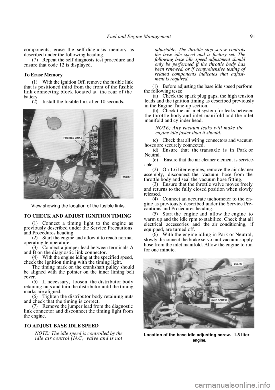
(1) With the ignition Off, remove the fusible link
that is positioned third from the front of the fusible
link connecting block located at the rear of the
battery. (2) Install the fusible link after 10 seconds.
View showing the location of the fusible links.
TO CHECK AND ADJUST IGNITION TIMING
(1) Connect a timing light to the engine as
previously described under the Service Precautions
and Procedures heading.
(2) Start the engine and allow it to reach normal
operating temperature. (3) Connect a jumper lead between terminals A
and B on the diagnostic link connector. (4) With the engine idling at the specified speed,
check the ignition timing with the timing light.
The timing mark on the crankshaft pulley should
be aligned with the pointer on the inner liming belt
cover.
(5) If necessary, loosen the distributor body
retaining nuts and turn the distributor until the timing
marks are aligned. (6) Tighten the distributor body retaining nuts
and check that the timing is correct. (7) Remove the jumper lead from the diagnostic
link connector and disconnect the timing light from
the engine.
TO ADJUST BASE IDLE SPEED
NOTE: The idle speed is controlled by the
idle air control (IAC) valve and is not
adjustable. The throttle stop screw controls
the base idle speed a nd is factory set. The
following base idle speed adjustment should
only be performed if the throttle body has
been renewed, or if comprehensive testing of
related components indicates that adjust-
ment is required.
(1) Before adjusting the base idle speed perform
the following tests;
(a) Check the spark plug gaps, the high tension
leads and the ignition timin g as described previously
in the Engine Tune-up section.
(b) Check the air inlet syst em for leaks between
the throttle body and inlet manifold and the inlet
manifold and cylinder head.
NOTE; Any vacuum leaks will make the
engine idle faster than it should.
(c) Check that all wiring connectors and vacuum
hoses are securely connected. (d) Ensure that the transaxle is in Park or
Neutral. (e) Ensure that the air cleaner element is service-
able.
(2) On 1.6 liter engines, remove the air cleaner
assembly, disconnect the vacuum hose from the
throttle body and seal the vacuum hose fitting.
(3) Ensure that the throttle valve moves freely
and returns to the fully closed position when slowly
released. (4) Connect an accurate tachometer to the en-
gine as previously descri bed under the Service Pre-
cautions and Procedures heading.
(5) Start the engine and allow the engine to
warm up and the idle rpm to stabilize. Check that all
electrical accessories and the air conditioning, if
equipped, are turned off. (6) With the engine idling in Park or Neutral,
slowly disconnect the brake servo unit vacuum supply
hose from the inlet manifold. Allow the engine to run
for one minute.
Location of the base idle adjusting screw. 1.8 liter
engine.
Page 95 of 238
Fuel and Engine Management 95
(3) Disconnect the vacuum hose from the pres-
sure regulator.
(4) Release the fuel hose clamps, disconnect the
hoses from the pressure regulator and remove the
pressure regulator. Installation is a reversal of the removal procedure
ensuring that the fuel hose clamps are tightened
securely.
To Remove and Install — 1.6 Liter Engine
(1) Depressurize the fuel system as previously
described. (2) Disconnect the negative battery terminal.
(3) Remove the air cleaner assembly. If neces-
sary, refer to the Air Cleane r Assembly heading in this
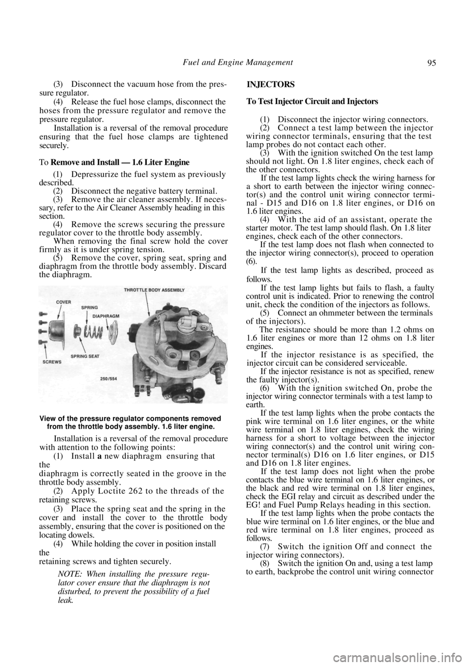
section. (4) Remove the screws securing the pressure
regulator cover to the throttle body assembly. When removing the final screw hold the cover
firmly as it is under spring tension.
(5) Remove the cover, spring seat, spring and
diaphragm from the thrott le body assembly. Discard
the diaphragm.
View of the pressure regulator components removed
from the throttle body assembly. 1.6 liter engine.
Installation is a reversal of the removal procedure
with attention to the following points:
(1) Install a new diaphragm ensuring that
the
diaphragm is correctly seat ed in the groove in the
throttle body assembly. (2) Apply Loctite 262 to the threads of the
retaining screws.
(3) Place the spring seat and the spring in the
cover and install the cover to the throttle body
assembly, ensuring that the cover is positioned on the
locating dowels. (4) While holding the cover in position install
the
retaining screws and tighten securely.
NOTE: When installing the pressure regu-
lator cover ensure that the diaphragm is not
disturbed, to prevent the possibility of a fuel
leak.
INJECTORS
To Test Injector Circuit and Injectors
(1) Disconnect the injector wiring connectors.
(2) Connect a test lamp between the injector
wiring connector terminals, ensuring that the test
lamp probes do not contact each other. (3) With the ignition switched On the test lamp
should not light. On 1.8 liter engines, check each of
the other connectors.
If the test lamp lights check the wiring harness for
a short to earth between the injector wiring connec-
tor(s) and the control unit wiring connector termi-
nal - D15 and D16 on 1.8 liter engines, or D16 on
1.6 liter engines.
(4) With the aid of an assistant, operate the
starter motor. The test lamp should flash. On 1.8 liter
engines, check each of the other connectors.
If the test lamp does not flash when connected to
the injector wiring connecto r(s), proceed to operation
(6).
If the test lamp lights as described, proceed as
follows.
If the test lamp lights but fails to flash, a faulty
control unit is indicated. Pr ior to renewing the control
unit, check the condition of the injectors as follows.
(5) Connect an ohmmeter between the terminals
of the injectors).
The resistance should be more than 1.2 ohms on
1.6 liter engines or more than 12 ohms on 1.8 liter
engines.
If the injector resistance is as specified, the
injector circuit can be considered serviceable.
If the injector resistance is not as specified, renew
the faulty injector(s).
(6) With the ignition switched On, probe the
injector wiring connector terminals with a test lamp to
earth.
If the test lamp lights when the probe contacts the
pink wire terminal on 1.6 liter engines, or the white
wire terminal on 1.8 liter engines, check the wiring
harness for a short to volt age between the injector
wiring connector(s) and the control unit wiring con-
nector terminal(s) D16 on 1.6 liter engines, or D15
and D16 on 1.8 liter engines.
If the test lamp does not light when the probe
contacts the blue wire termin al on 1.6 liter engines, or
the black and red wire term inal on 1.8 liter engines,
check the EGI relay and circ uit as described under the
EG! and Fuel Pump Relays heading in this section.
If the test lamp lights when the probe contacts the
blue wire terminal on 1.6 lite r engines, or the blue and
red wire terminal on 1.8 liter engines, proceed as
follows.
(7) Switch the ignition Off and connect the
injector wiring connectors). (8) Switch the ignition On and, using a test lamp
to earth, backprobe the cont rol unit wiring connector
Page 96 of 238
96 Fuel and Engine Management
terminal D16 on 1.6 liter engines, or D15 and D16
on
1.8 liter engines.
The test lamp should light.
If the test lamp does not light check the wiring
harness for continuity between the injector wiring
connector(s) and the control unit wiring connector
terminals.
Repair or renew the wiring harness as necessary.
To Remove and Install Injectors and Fuel Rail — 1.8
Liter Engine.
(1) Depressurize the fuel system as previously
described.
(2) Disconnect the negative battery terminal.
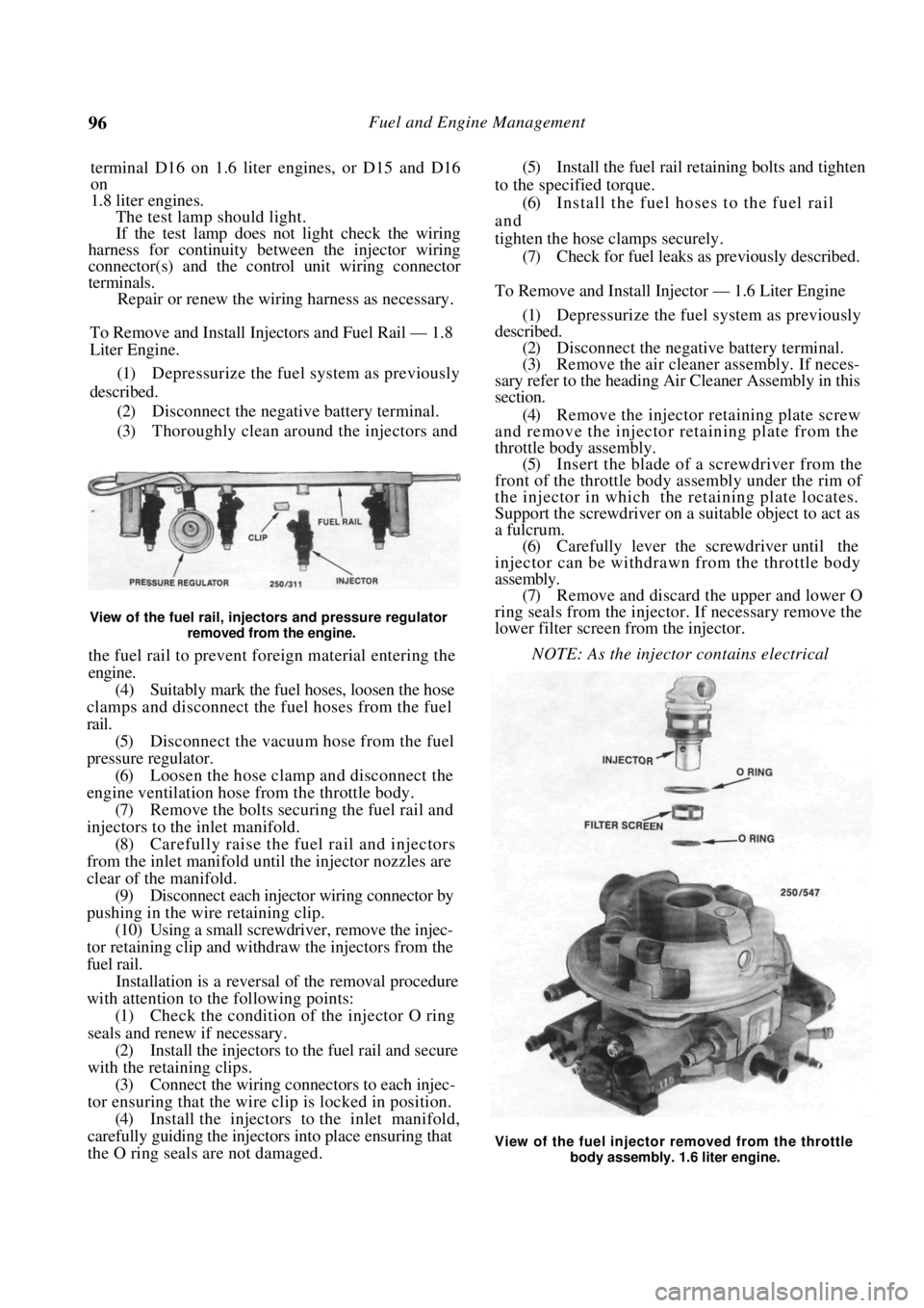
(3) Thoroughly clean around the injectors and
View of the fuel rail, injectors and pressure regulator
removed from the engine.
the fuel rail to prevent foreign material entering the
engine.
(4) Suitably mark the fuel hoses, loosen the hose
clamps and disconnect the fuel hoses from the fuel
rail. (5) Disconnect the vacuum hose from the fuel
pressure regulator. (6) Loosen the hose clamp and disconnect the
engine ventilation hose from the throttle body. (7) Remove the bolts securing the fuel rail and
injectors to the inlet manifold. (8) Carefully raise the fuel rail and injectors
from the inlet manifold until the injector nozzles are
clear of the manifold. (9) Disconnect each injector wiring connector by
pushing in the wire retaining clip.
(10) Using a small screwdriver, remove the injec-
tor retaining clip and withdraw the injectors from the
fuel rail.
Installation is a reversal of the removal procedure
with attention to the following points:
(1) Check the condition of the injector O ring
seals and renew if necessary. (2) Install the injectors to the fuel rail and secure
with the retaining clips. (3) Connect the wiring connectors to each injec-
tor ensuring that the wire clip is locked in position. (4) Install the injectors to the inlet manifold,
carefully guiding the injectors into place ensuring that
the O ring seals are not damaged.
(5) Install the fuel rail retaining bolts and tighten
to the specified torque. (6) Install the fuel hoses to the fuel rail
and
tighten the hose clamps securely.
(7) Check for fuel leaks as previously described.
To Remove and Install Injector — 1.6 Liter Engine
(1) Depressurize the fuel system as previously
described. (2) Disconnect the negative battery terminal.
(3) Remove the air cleaner assembly. If neces-
sary refer to the heading Air Cleaner Assembly in this
section.
(4) Remove the injector retaining plate screw
and remove the injector retaining plate from the
throttle body assembly. (5) Insert the blade of a screwdriver from the
front of the throttle body assembly under the rim of
the injector in which the retaining plate locates.
Support the screwdriver on a suitable object to act as
a fulcrum. (6) Carefully lever the screwdriver until the
injector can be withdrawn from the throttle body
assembly.
(7) Remove and discard the upper and lower O
ring seals from the injector . If necessary remove the
lower filter screen from the injector.
NOTE: As the injector contains electrical
View of the fuel injector removed from the throttle body assembly. 1.6 liter engine.
Page 98 of 238
Fuel and Engine Management
(8) Remove the bolts retaining the intermediate
exhaust pipe to the rear of the catalytic converter,
remove the bolt securing the exhaust mounting to the
underbody and slightly lower the intermediate exhaust
pipe. Support the intermediate pipe to prevent the
tailpipe fouling the lower bumper panel.
(9) Remove the bolts retaining the stabilizer bar
mounting brackets to the underbody and allow the
stabilizer bar to drop.
(10) Remove the bolts retaining the exhaust heat
shield to the underbody, located at the front of the
fuel tank. (11) Remove the handbrake cable mounting
bracket retaining nuts and remove the mounting
brackets from the mounting studs. (12) Remove the fuel tank retaining bolts and
maneuver the fuel tank from the vehicle. Installation is a reversal of the removal procedure
with attention to the following points:
(1) When installing the fuel tank, ensure that the
fuel pump wiring harness is directed through the
aperture in the floor. (2) Install the stabilizer bar mounting
bracket
bolts and tighten to the specified torque. Refer to the
Rear Suspension section.
(3) Using a new gasket, install the intermediate
exhaust pipe to the catalyti c converter ensuring that
the earth wire terminal is installed and tighten the
bolts securely. (4) Connect the fuel filler neck hose, the fuel
check valve hose and the breat her hose ensuring that
they are secured firmly. (5) Tighten the fuel tank drain plug to the
specified torque. (6) Connect the fuel hoses to the fuel pump,
using the marks made during removal to ensure
correct installation. (7) Install the fuel pump wiring harness and the
rubber grommet to the fuel pump cover plate. Install
the cover plate and tighten the retaining bolts se-
curely.
(8) Connect the fuel pump wiring connector
securely. (9) Check for fuel leaks as previously described.
6. AIR FLOW COMPONENTS
NOTE: Before proceeding with any of the
operations in this section, refer to the Ser-
vice Precautions and Procedures heading.
AIR CLEANER ASSEMBLY
To Renew Element
The procedure for renewing the air cleaner ele-
ment is covered in the Engine Tune-up section.
To Remove and Install — 1.8 Liter Engine
(1) Disconnect the negative battery terminal.
(2) Release the air intake hose retaining clamps,
disconnect the hose from the air cleaner upper
housing and the throttle body and remove the hose. (3) Remove the screw securing the air cleaner
intake duct to the front panel mounting bracket. (4) Remove the hexagon head screws retaining
the air cleaner mounting bracket to the right hand
inner mudguard and remove the air cleaner from the
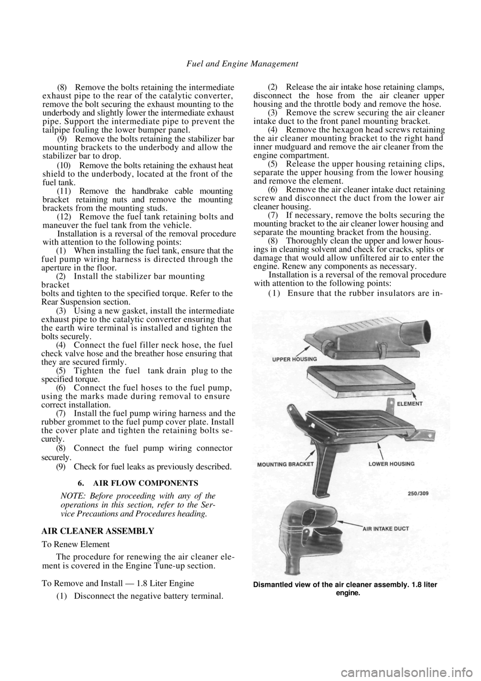
engine compartment. (5) Release the upper housing retaining clips,
separate the upper housing from the lower housing
and remove the element. (6) Remove the air cleaner intake duct retaining
screw and disconnect the duct from the lower air
cleaner housing. (7) If necessary, remove the bolts securing the
mounting bracket to the ai r cleaner lower housing and
separate the mounting bracket from the housing. (8) Thoroughly clean the upper and lower hous-
ings in cleaning solvent and check for cracks, splits or
damage that would allow unfiltered air to enter the
engine. Renew any components as necessary.
Installation is a reversal of the removal procedure
with attention to the following points:
(1) Ensure that the r ubber insulators are in-
Dismantled view of the ai r cleaner assembly. 1.8 liter
engine.
Page 99 of 238
Fuel and Engine Management 99
stalled on each side of the air cleaner mounting
bracket when installing the mounting bolts.
(2) If renewing the element, ensure that the
specified element is installed and is correctly seated in
the air cleaner housing. (3) Ensure that the air intake hose clamps are
tightened securely.
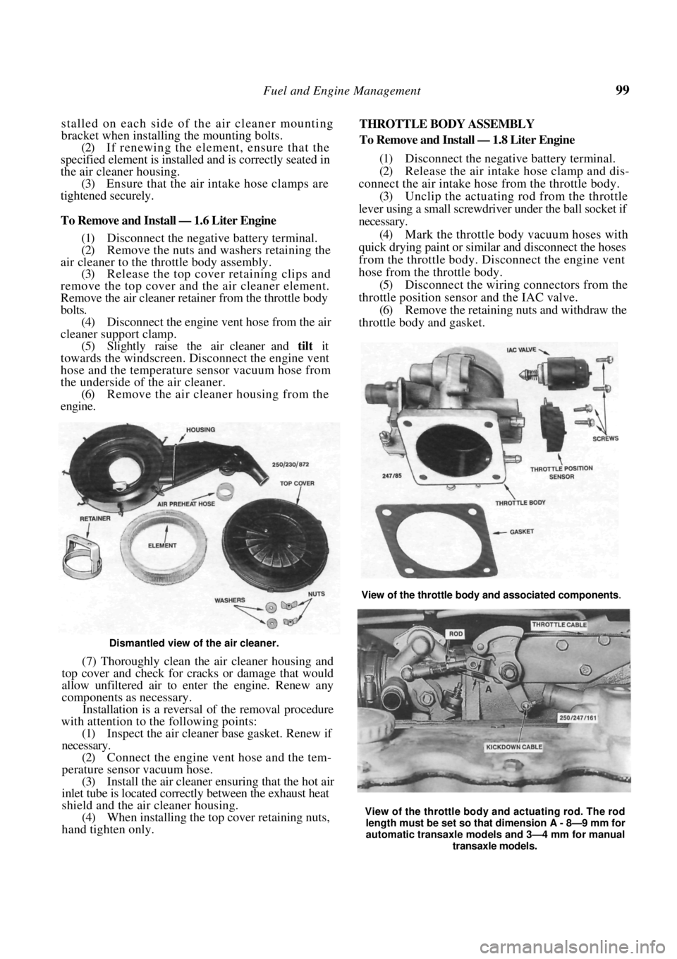
To Remove and Install — 1.6 Liter Engine
(1) Disconnect the negative battery terminal.
(2) Remove the nuts and washers retaining the
air cleaner to the throttle body assembly. (3) Release the top cover retaining clips and
remove the top cover and the air cleaner element.
Remove the air cleaner retainer from the throttle body
bolts. (4) Disconnect the engine vent hose from the air
cleaner support clamp. (5) Slightly raise the air cleaner and tilt it
towards the windscreen. Disc onnect the engine vent
hose and the temperature sensor vacuum hose from
the underside of the air cleaner. (6) Remove the air cleaner housing from the
engine.
Dismantled view of the air cleaner.
(7) Thoroughly clean the air cleaner housing and
top cover and check for cracks or damage that would
allow unfiltered air to enter the engine. Renew any
components as necessary.
Installation is a reversal of the removal procedure
with attention to the following points:
(1) Inspect the air cleaner base gasket. Renew if
necessary. (2) Connect the engine vent hose and the tem-
perature sensor vacuum hose. (3) Install the air cleaner ensuring that the hot air
inlet tube is located correc tly between the exhaust heat
shield and the air cleaner housing. (4) When installing the top cover retaining nuts,
hand tighten only. THROTTLE BODY ASSEMBLY
To Remove and Install — 1.8 Liter Engine
(1)
Disconnect the negative battery terminal.
(2) Release the air intake hose clamp and dis-
connect the air intake hose from the throttle body. (3) Unclip the actuating rod from the throttle
lever using a small screwdriver under the ball socket if
necessary.
(4) Mark the throttle body vacuum hoses with
quick drying paint or similar and disconnect the hoses
from the throttle body. Disconnect the engine vent
hose from the throttle body. (5) Disconnect the wiring connectors from the
throttle position sensor and the IAC valve.
(6) Remove the retaining nuts and withdraw the
throttle body and gasket.
View of the throttle body and actuating rod. The rod
length must be set so that dimension A - 8—9 mm for
automatic transaxle models and 3—4 mm for manual
transaxle models.
View of the throttle body and associated components.