boot NISSAN PULSAR 1987 Workshop Manual
[x] Cancel search | Manufacturer: NISSAN, Model Year: 1987, Model line: PULSAR, Model: NISSAN PULSAR 1987Pages: 238, PDF Size: 28.91 MB
Page 86 of 238
86 Fuel and Engine Management
other. The fuel pressure is maintained at a constant
pressure relevant to the manifold vacuum. A dispos-
able paper element fuel filter is mounted on the engine
bulkhead.
The amount of fuel injected is relevant to the time
the injector remains open. The basic time the injector
remains open is governed by the control unit which
uses information from the various sensors to give
optimum engine efficiency for given conditions.
The idle air control (IAC) valve controls the fast
idle speed during engine warm up and maintains the
basic idle speed at a set value by compensating for
loads such as air conditioning or the selection of Drive
on automatic transaxle models.
The throttle body assembly is mounted to the
inlet manifold and controls the amount of air entering
the engine by the action of the throttle valve.
Efficient operation of the EFI system depends on
accurate signals being receiv ed by the control unit and
controlled air flow beyond the throttle valve. There-
fore it is essential that all air, fuel and electrical
connections be clean and tight.
3. SERVICE PRECAUTIONS AND
PROCEDURES
Electronic ignition systems can produce danger-
ously high voltages in both the primary and secondary
circuits. For this reason, extreme care must be taken
when working on or near the ignition system.
Do not start the engine if the battery terminals are
not clean and tight.
Do not use the fast charge or boost settings on a
battery charger to start the engine.
Do not disconnect the battery terminals while the
engine is running.
Disconnect the battery terminals before charging
the battery.
Disconnect the negative ba ttery terminal before
working on the engine management system.
Do not subject the control unit to temperatures
above 80 deg C.
Ensure that all wiring connectors are clean and
tight.
Disconnect the battery terminals and the control
unit wiring connectors before attempting any welding
operations.
Do not direct a steam cleaning or pressure
washing nozzle at engine management components
when cleaning the engine.
Ensure that the ignition is Off prior to disconnect-
ing the battery terminals, fusible links or the control
unit wiring connectors.
TO CONNECT ELECTRICAL TEST
EQUIPMENT
NOTE: Some types of tachometers, timing
lights and ignition system analysers are not
compatible with this engine management
system and may result in incorrect readings.
It is therefore recommended that the man-
ufacturer of the lest equipment be consulted
before proceeding to use the equipment.
If a test procedure requires the use of a
test lamp or voltmeter, ensure that only the
specified instrument is used to prevent mis-
leading diagnosis.
MULTIMETER
It is essential that in all tests where voltage or
resistance is to be measur ed, a digital display multi-
meter with a minimum 10 megohms impedance be
used.
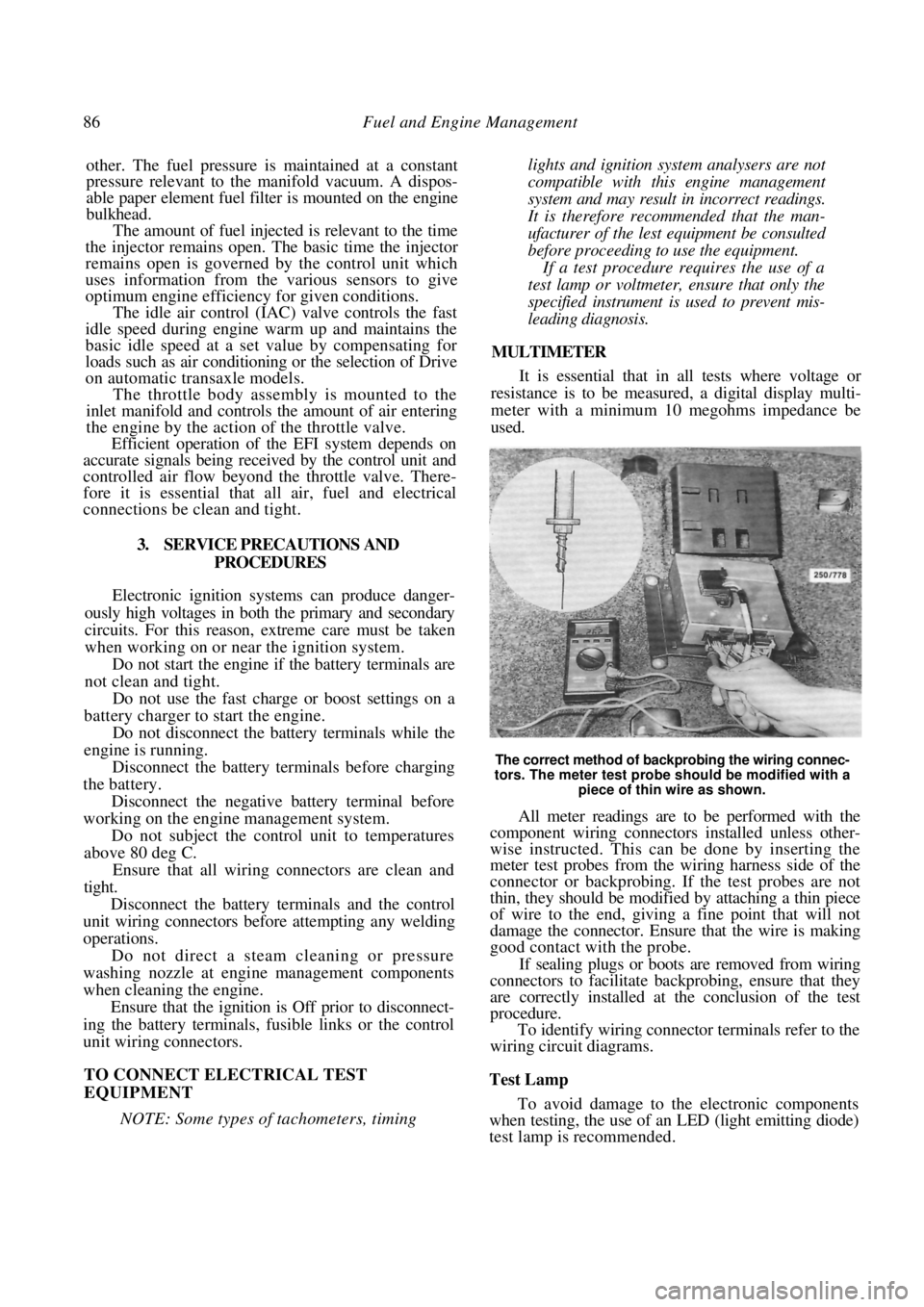
The correct method of backprobing the wiring connec-
tors. The meter test probe should be modified with a piece of thin wire as shown.
All meter readings are to be performed with the
component wiring connectors installed unless other-
wise instructed. This can be done by inserting the
meter test probes from the wiring harness side of the
connector or backprobing. If the test probes are not
thin, they should be modified by attaching a thin piece
of wire to the end, giving a fine point that will not
damage the connector. Ensure that the wire is making
good contact with the probe.
If sealing plugs or boots are removed from wiring
connectors to facilitate bac kprobing, ensure that they
are correctly installed at the conclusion of the test
procedure.
To identify wiring connector terminals refer to the
wiring circuit diagrams.
Test Lamp
To avoid damage to the electronic components
when testing, the use of an LED (light emitting diode)
test lamp is recommended.
Page 128 of 238
128 Manual Transaxle and Drive Shafts
TRANSAXLE NOISE (FORWARD GEARS
ENGAGED, VEHICLE MOVING)
(1) Insufficient lubricant: Fill the transaxle with
the correct grade and quantity of oil. (2) Worn input shaft or mainshaft bearings:
Overhaul the transaxle and renew the faulty bearings. (3) Chipped or pitted gears: Check and overhaul
the transaxle and renew the faulty gears. (4) Damaged or worn sync hroniser assemblies:
Overhaul the transaxle and renew the synchroniser
assemblies.
FINAL DRIVE GEAR NOISE
(1) Insufficient lubricant: Fill the transaxle case
with the correct grade and quantity of oil. (2) Chipped or pitted final drive gear and/or ring
gear: Overhaul the transaxle and renew components as
necessary. (3) Worn differential carrier bearings: Overhaul
the differential assembly.
(4) Worn mainshaft or input shaft bearings:
Overhaul the transaxle.
NOTE: Check the oil level in the transaxle
case and the condition of the front hub
bearings and drive shaft joints prior to
overhauling the transaxle.
EXCESSIVE BACKLASH IN FINAL DRIVE
(1) Excessive end float in the differential carrier
bearings due to worn or incorrect bearing preload
adjustment: Check and adjust the bearing preload or
renew the bearings.
(2) Ring gear to differential case bolts loose:
Overhaul the transaxle and tighten the bolts to the
specified torque.
(3) Excessive wear in the final drive gear: Check
and overhaul the transaxle. (4) Excessive wear in the differential pinions,
side gears or pinion shaft: Overhaul the differential
assembly.
NOTE: Prior to overhauling the differential,
check the serviceability of the C.V joints on
the drive shafts.
NO DRIVE IN ANY GEAR
(1) Sheared ring gear to differential case bolts:
Overhaul the differential assembly.
(2) Broken drive shaft: Check and renew com-
ponents as necessary.
(3) Inner C.V. joint shaft out of mesh with
differential side gear: Weak or broken inner C.V. joint
shaft snap ring. Renew as necessary.
NOISE OR VIBRATION IN DRIVE SHAFTS
( 1 ) Bent or twisted drive shafts: Check and
renew the drive shafts as necessary.
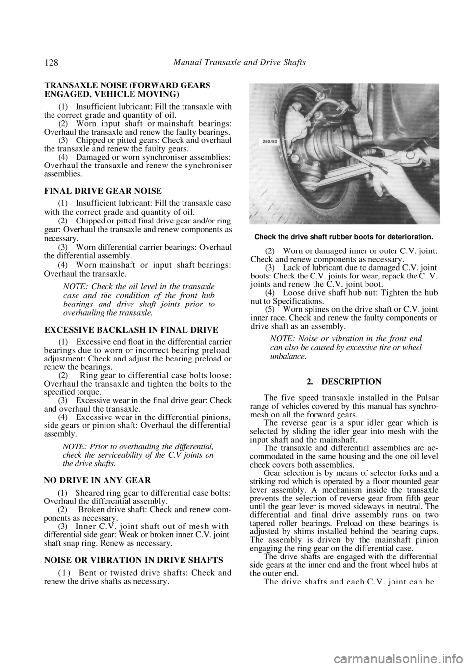
Check the drive shaft rubber boots for deterioration.
(2) Worn or damaged inner or outer C.V. joint:
Check and renew components as necessary. (3) Lack of lubricant due to damaged C.V. joint
boots: Check the C.V. joints for wear, repack the C. V.
joints and renew th e C.V. joint boot.
(4) Loose drive shaft hub nut: Tighten the hub
nut to Specifications. (5) Worn splines on the drive shaft or C.V. joint
inner race. Check and renew the faulty components or
drive shaft as an assembly.
NOTE: Noise or vibration in the front end
can also be caused by excessive tire or wheel
unbalance.
2. DESCRIPTION
The five speed transaxle installed in the Pulsar
range of vehicles covered by this manual has synchro-
mesh on all the forward gears.
The reverse gear is a spur idler gear which is
selected by sliding the idler gear into mesh with the
input shaft and the mainshaft.
The transaxle and differential assemblies are ac-
commodated in the same housing and the one oil level
check covers both assemblies.
Gear selection is by mean s of selector forks and a
striking rod which is operated by a floor mounted gear
lever assembly. A mechanism inside the transaxle
prevents the selection of re verse gear from fifth gear
until the gear lever is moved sideways in neutral. The
differential and final dr ive assembly runs on two
tapered roller bearings. Pr eload on these bearings is
adjusted by shims installed behind the bearing cups.
The assembly is driven by the mainshaft pinion
engaging the ring gear on the differential case.
The drive shafts are engaged with the differential
side gears at the inner end and the front wheel hubs at
the outer end.
The drive shafts and each C.V. joint can be
Page 129 of 238
Manual Transaxle and Drive Shafts 129
renewed as individual units. The C.V. joints are
lubricated in manufacture and need no attention in
service unless one of the r ubber boots is damaged. In
this case the joint can be cl eaned and repacked with
the recommended grease and a new boot installed.
From July 1989, Pulsar Q and Vector SSS manual
transaxle models are equipped with a limited slip
differential incorporating a viscous coupling. The
coupling is not repairable and must be renewed as an
assembly if unserviceable. A test procedure for the
viscous coupling is included in the text in this section.
3. TRANSAXLE ASSEMBLY
Special Equipment Required:
To Dismantle and Assemble — Puller set, press
and press plates, dial gauge
To Measure Mainshaft Turning Torque —
Suitable slotted adaptor and torque gauge
TO REMOVE AND INSTAL
(1) Raise the front of the vehicle and support it
on chassis stands.
(2) Remove the battery as described in the
Electrical System section. (3) Remove the drive shafts as described later in
this section. (4) Disconnect and remove the starter motor as
described in the Elect rical System section.
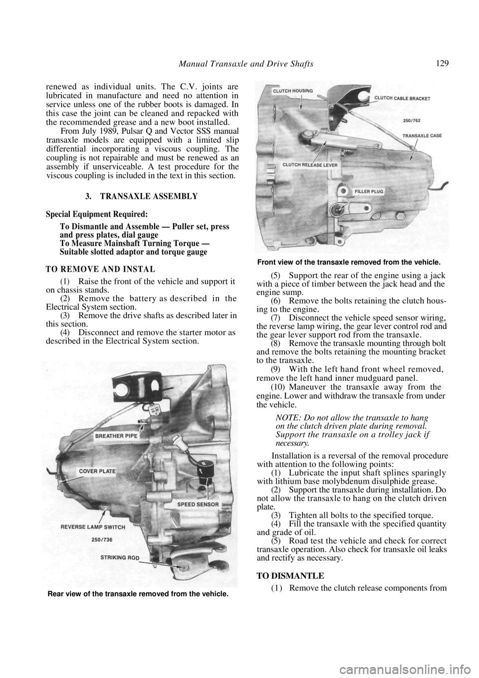
Front view of the transaxle removed from the vehicle.
(5) Support the rear of the engine using a jack
with a piece of timber between the jack head and the
engine sump.
(6) Remove the bolts retaining the clutch hous-
ing to the engine. (7) Disconnect the vehicle speed sensor wiring,
the reverse lamp wiring, the gear lever control rod and
the gear lever support rod from the transaxle. (8) Remove the transaxle mounting through bolt
and remove the bolts retaining the mounting bracket
to the transaxle.
(9) With the left hand front wheel removed,
remove the left hand inner mudguard panel. (10) Maneuver the transaxle away from the
engine. Lower and withdraw the transaxle from under
the vehicle.
NOTE: Do not allow the transaxle to hang
on the clutch driven plate during removal.
Support the transaxle on a trolley jack if
necessary.
Installation is a reversal of the removal procedure
with attention to the following points:
(1) Lubricate the input shaft splines sparingly
with lithium base molybdenum disulphide grease. (2) Support the transaxle during installation. Do
not allow the transaxle to hang on the clutch driven
plate. (3) Tighten all bolts to the specified torque.
(4) Fill the transaxle with the specified quantity
and grade of oil. (5) Road test the vehicle and check for correct
transaxle operation. Also ch eck for transaxle oil leaks
and rectify as necessary.
TO DISMANTLE
(1) Remove the clutch release components from Rear view of the transaxle removed from the vehicle.
Page 136 of 238
136 Manual Transaxle and Drive Shafts
right hand side gear and the adjacent spacer in an area
where there is no oil groove in the differential case.
(d) Insert another 0.03 mm feeler gauge diago-
nally opposite the first feeler gauge to avoid tilting the
side gear.
(e) Insert a splined adaptor into the right hand
side gear and attempt to rotate the gear by hand.
(f) If the gear cannot be rotated, change the
thickness of the left hand side gear spacer, repeating
the test until the gear can be rotated.
NOTE: Spacers are available in thicknesses
from 0.8 mm to 1.5 mm in increments of
0.1 mm.
(g) Remove the 0.03 mm feel er gauges and insert
0.09 mm feeler gauges to the same position. The gear
should lock.
(h) The spacer selection is correct when the right
hand side gear can be rotated with 0.03 mm feeler
gauges inserted but locks when 0.09 mm feeler gauges
are inserted.
(18) Install the ring gear to the differential case
with the chamfered edge of the ring gear inwards. (19) Install and tighten the retaining bolts in
a
diagonal sequence to the specified torque.
(20) Install a new speedometer drive gear to
the
differential case. Install the stopper adjacent to the
drive gear.
(21) Install the differentia] carrier bearing
cones
and roller assemblies to the differential case.
(22) Remove the adjusting shim from behind the
carrier bearing outer race in the transaxle case and
replace the outer race in the transaxle case.
(23) Install the differential assembly to the clutch
housing. (24) Install the transaxle case to the clutch housing
and tighten the retaining bolts to the specified torque.
(25) Mount a dial gauge to the clutch housing so
that the contact point is resting on the differential
case. (26) Insert a bar through the opposite side gear
and, contacting the pinion shaft, raise and lower the
differential case and measure the end float in the
carrier bearings. (27) Using the following table, select a shim to
correspond to the relevant end float.
END FLOAT SHIM THICKNESS
0.30-0.34 mm....................................................0.64 mm
0.34-0.38 mm................................................... 0.68 mm
0.38-0.42 mm................................................... 0.72 mm
0.42-0.46 mm................................................... 0.76 mm
0.46-0.50 mm................................................... 0.80 mm
0.50-0.54 mm................................................... 0.84 mm
0.54-0.58 mm................................................... 0.88 mm
0.58-0.62 mm................................................... 0.92 mm
0.62-0.66 mm................................................... 0.96 mm
0.66-0.70 mm................................................... 1.00 mm
0.70-0.74 mm................................................... 1.04 mm
0.74-0.78 mm ................................................... 1.08 mm
0.78-0.82 mm ................................................... 1.12 mm
0.82-0.86 mm ................................................... 1.16 mm
0.86-0.90 mm ................................................... 1.20 mm
0.90-0.94 mm ................................................... 1.24 mm
0.94-0.98 mm ................................................... 1.28 mm
0.98-1.02 mm ................................................... 1.32 mm
1.02-1.06 mm ................................................... 1.36 mm
1.06-1.10 mm ................................................... 1.40 mm
1.10-1.14 mm ................................................... 1.44 mm
1.14-1.18 mm ................................................... 1.48 mm
1.18-1.22 mm ................................................... 1.52 mm
1.22-1.26 mm ................................................... 1.56 mm
1.26-1.30 mm ................................................... 1.60 mm
1.30-1.34 mm ................................................... 1.64 mm
1.34-1.38 mm ................................................... 1.68 mm
1.38-1.42 mm ................................................... 1.72 mm
1.42-1.46 mm ................................................... 1.76 mm
The thickest shim available is 0.88 mm. Multiple
shims are required above this thickness.
(28) Install the shim behind the carrier
bearing
outer race in the transaxle case and assemble the unit
once more. (29) Using a suitable slotted adaptor engage the
pinion shaft and using a to rque gauge, measure the
differential turning torque. The turning torque when new carrier bearings
have been installed should be 3.9-7.8 Nm or slightly
lower if the original carrier bearings have been
replaced.
(30) Assemble the transaxle and measure the total
turning torque of the diff erential assembly and the
mainshaft. The total turning torque should be 5.9 to
13.7 Nm with new bearings or slightly lower if the
original bearings have been replaced.
5. GEAR LEVER ASSEMBLY
TO DISMANTLE AND ASSEMBLE
(1) Remove the gear lever knob and remove the
centre console as described in the Body section. If not
previously removed, remove the rubber boot sur-
rounding the gear lever. (2) Raise the front of the vehicle and support it
on chassis stands. Remove the catalytic converter and
heat shield as described in the Engine section.
(3) Remove the bolt and disconnect the control
rod from the bottom of the gear lever, noting the
position of the return spring and bracket.
(4) Remove the nuts retaining the gear lever
socket to the support rod. (5) Working inside the vehicle, lift the gear lever
out of the floor bracket. (6) Separate the lower rubber boot, socket,
spring seat, spring, upper ball seat and lower ball seat
from the gear lever, noting the location of each
component to aid assembly.
Page 138 of 238
138 Manual Transaxle and Drive Shafts
Brakes section if necessary. Suspend the caliper with
wire or cord attached to the coil spring.
(9) Hold the steering knuckle and hub assembly
and tap the drive shaft out of the hub using a soft
faced hammer.
(10) Drain the oil from the transaxle into a
container.
(11) Prise the drive shaft out of the transaxle and
remove the drive shaft from the vehicle.
Installation is a reversal of the removal procedure
with attention to the following points:
(1) Ensure that the drive sh aft is firmly attached
to the differential side gear by attempting to pull the
shaft out of the gear. (2) Tighten all nuts securely and install new split
pins. (3) Fill the transaxle with the specified grade and
quantity of oil.
TO DISMANTLE AND ASSEMBLE
(1) Remove the drive shaft from the vehicle as
previously described.
(2) Remove and discard both the inner C.V.
joint boot retaining clips from the inner C.V. joint. (3) Roll back the large en d of the inner C.V.-
joint boot using a thin blade screwdriver, prise out the
C.V. joint retaining ring.
(4) Withdraw the C.V. joint housing from the
drive shaft and ball assembly. (5) Remove the inner snap ring retaining the ball
assembly to the drive shaft and withdraw the ball
assembly. (6) Remove the remaining inner C.V. joint re-
taining snap ring and the C.V. joint boot from the
drive shaft. (7) Noting their installed positions remove the
cage and ball assembly off the inner race and press the
balls out of the cage. (8) Remove and discard the clips retaining the
outer C.V. joint boot to the drive shaft and remove
the C.V. joint boot.
NOTE: The outer C.V. joint cannot be
dismantled.
(9) Wash all parts in a suitable solvent and blow
dry with compressed air.
(10) Inspect the ball contact faces of the inner ball
race and C.V. joint housing for pitting and wear.
(11) Inspect the ball cage and the balls for wear
and damage. (12) Rotate the drive shaft with the outer C.V.
joint at a sharp angle and inspect the internal
components of the outer C.V. joint for wear and
damage. Renew if necessary by tapping the C.V. joint
from the drive shaft.
NOTE: Do not reuse the retaining snap ring
if the C. V. joint is removed from the drive
shaft.
(13) Check the C.V. joint boots for damage and
deterioration. (14) Renew all worn or damaged components as
necessary. Assembly is a reversal of the dismantling proce-
dure with attention to the following points:
(1) Thoroughly pack the outer C.V. joint with
molybdenum disulphide grease. (2) Install the outer C.V. joint boot and retain in
position using new retaining clips. Ensure that the
boot and the clips ar e correctly seated.
(3) Install the inner C.V. joint boot, small
end
first, onto the drive shaft and pull it well down the
shaft. (4) Install the outer snap ri ng for the inner C.V.
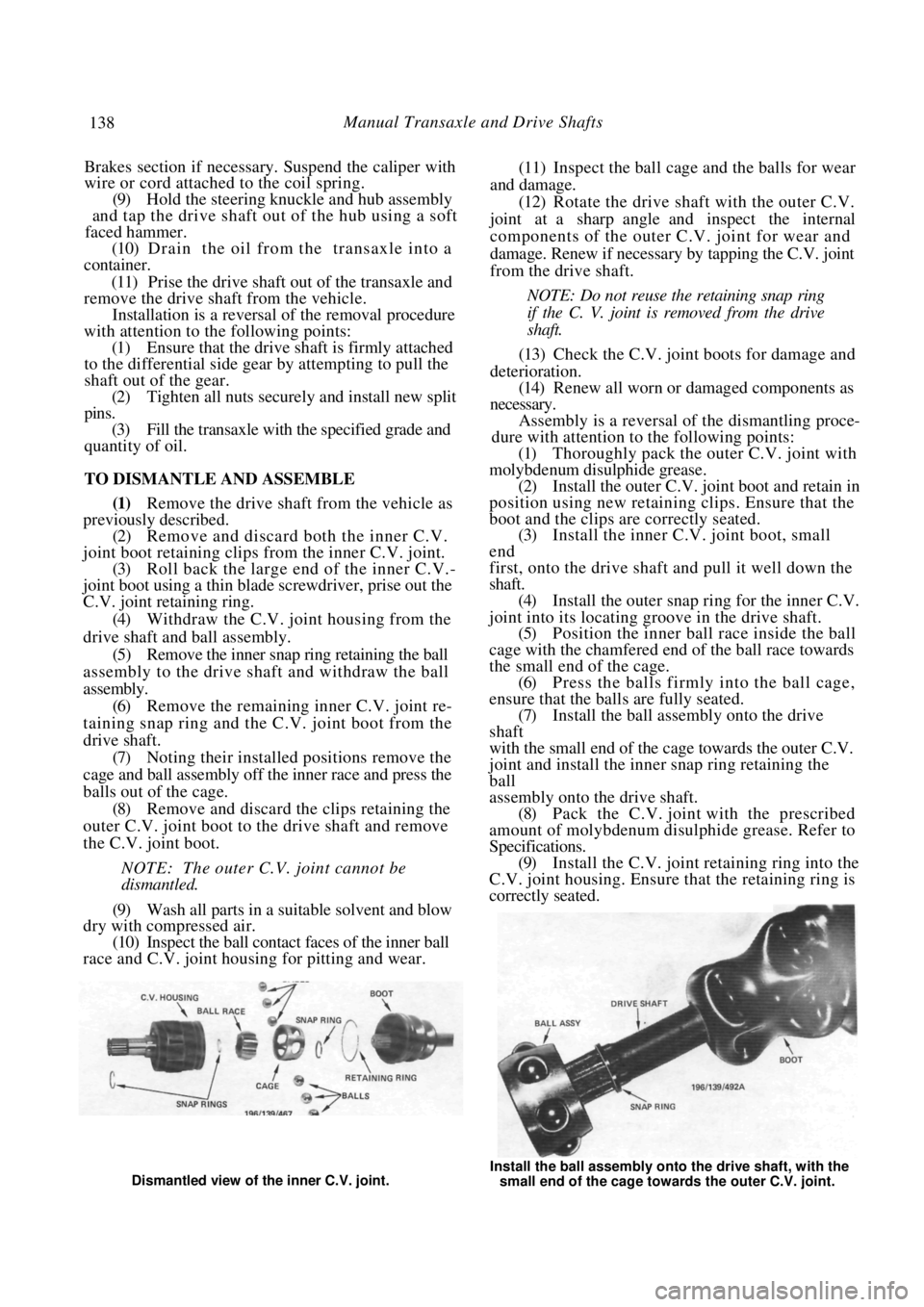
joint into its locating groove in the drive shaft. (5) Position the inner ball race inside the ball
cage with the chamfered end of the ball race towards
the small end of the cage. (6) Press the balls firmly into the ball cage,
ensure that the balls are fully seated. (7) Install the ball assem bly onto the drive
shaft
with the small end of the cage towards the outer C.V.
joint and install the inner snap ring retaining the
ball
assembly onto the drive shaft.
(8) Pack the C.V. joint with the prescribed
amount of molybdenum disul phide grease. Refer to
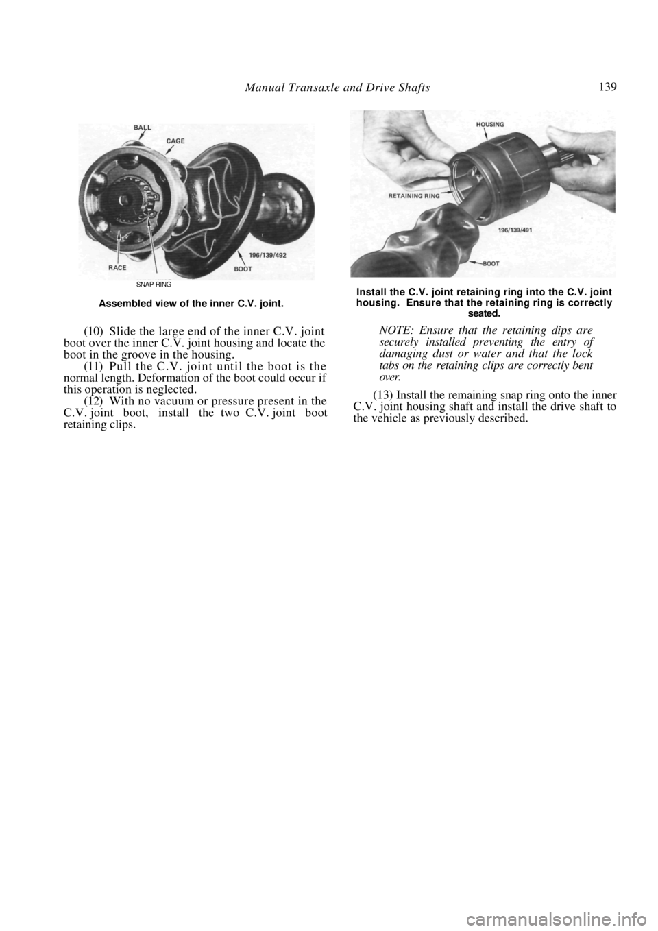
Specifications. (9) Install the C.V. joint retaining ring into the
C.V. joint housing. Ensure that the retaining ring is
correctly seated.
Dismantled view of the inner C.V. joint. Install the ball assembly onto the drive shaft, with the
small end of the cage towards the outer C.V. joint.
Page 139 of 238
Manual Transaxle and Drive Shafts 139
SNAP RING
Assembled view of the inner C.V. joint.
(10) Slide the large end of the inner C.V. joint
boot over the inner C.V. joint housing and locate the
boot in the groove in the housing.
(11) Pull the C.V. joint until the boot is the
normal length. Deformation of the boot could occur if
this operation is neglected. (12) With no vacuum or pressure present in the
C.V. joint boot, install the two C.V. joint boot
retaining clips.
Install the C.V. joint retain ing ring into the C.V. joint
housing. Ensure that the retaining ring is correctly
seated.
NOTE: Ensure that the retaining dips are
securely installed preven ting the entry of
damaging dust or water and that the lock
tabs on the retaining clips are correctly bent
over.
(13) Install the remaining snap ring onto the inner
C.V. joint housing shaft and install the drive shaft to
the vehicle as previously described.
Page 145 of 238
145
STEERING
PART 1. STEERING TROUBLE SHOOTING
FAULTS, CAUSES AND REMEDIES
EXCESSIVE PLAY OR LOOSENESS IN
STEERING GEAR
(1) Tie rod end ball joint loose or worn: Tighten
or renew the worn tie rod end ball joint. (2) Steering gear assembly loose on cross-
member: Inspect for damage and tighten the steering
gear mounting bolts. (3) Steering gear worn: Overhaul the steering
gear.
(2) Low fluid level in the power steering reser-
voir: Check for leakage, repa ir and/or renew the faulty
components. Top up the fluid level.
(3) Suspension worn or out of alignment: Check
the front suspension for wear, renew the worn com-
ponents and realign. (4) Misalignment between the steering gear and
column mountings: Check and align the steering gear
and column mountings. (5) Binding in the steering shaft universal coup-
ling joints: Check the join ts and renew if necessary.
(6) Ingress of dirt into the steering gear due to a
defective boot: Clean, check and lubricate the internal
components of the steering gear and renew the
defective boot. (7) Insufficient power steering pump pressure:
Check the pump drive belt tension and reservoir fluid
level. If necessary renew the pump assembly.
NOTE: Ensure that both front tires have
ample depth of tread and are inflated to the
correct pressure. Check the front suspension
components for wear before having the steer-
ing geometry checked. See the Front Sus-
pension section for the component checking
procedures.
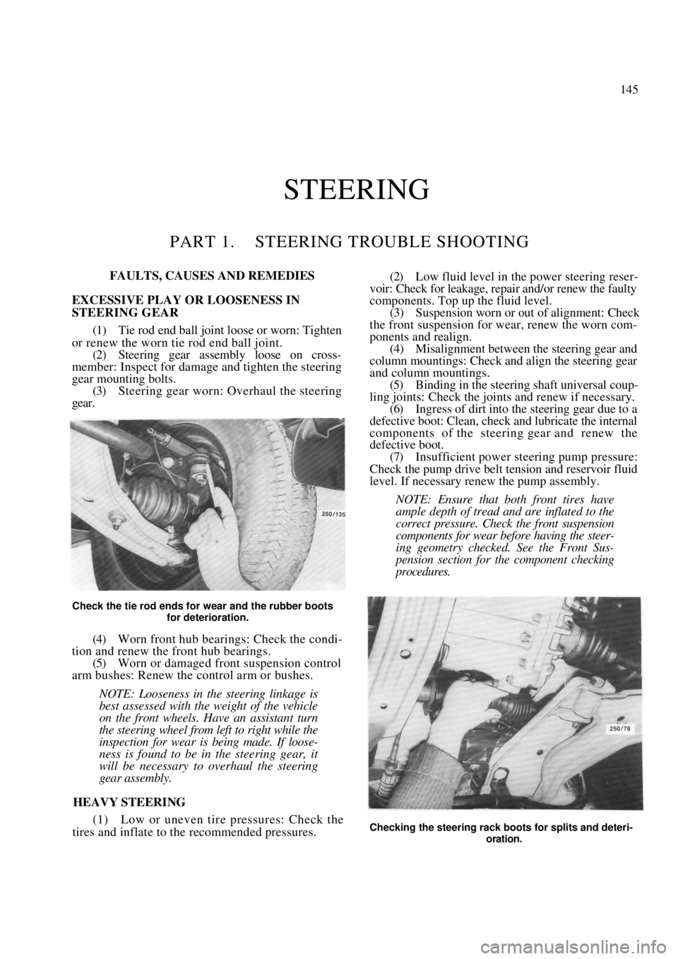
Check the tie rod ends for wear and the rubber boots for deterioration.
(4) Worn front hub bearings: Check the condi-
tion and renew the front hub bearings. (5) Worn or damaged front suspension control
arm bushes: Renew the control arm or bushes.
NOTE: Looseness in th e steering linkage is
best assessed with the weight of the vehicle
on the front wheels. Have an assistant turn
the steering wheel from left to right while the
inspection for wear is being made. If loose-
ness is found to be in the steering gear, it
will be necessary to overhaul the steering
gear assembly.
HEAVY STEERING
(1) Low or uneven tir e pressures: Check the
tires and inflate to the recommended pressures.
Checking the steering rack boot s for splits and deteri-
oration.
Page 147 of 238
147
PART 2. MANUAL STEERING
SPECIFICATIONS
Steering gear type ............................ Rack and pinion
Steering column type ...................... Energy absorbing
collapsible and tilt adjustable
Steering wheel free play
(maximum ) ...................................................... 35 mm
Linkage........................... Direct from rack ends to t i e
rods and steering knuckles
Turns lock to lock ................................................. 3.6
Steering column length .................. 534.7-537.3 mm
Steering gear lubricant.............. Castrol EPL 1 grease
TORQUE WRENCH SETTINGS
Steering wheel retaining nut ............................ 39 Nm
Steering gear to bulkhead
mounting bolts .............................................. 108 Nm
Tie rod to steering knuckle nut...................... 98 Nm
Tie rod to tie rod end locknut ....................... 98 Nm
Tie rod ball housing to rack............................ 88 Nm
Steering column to mounting
bracket bolt ...................................................... 14 Nm
Steering column universal
coupling joint pinch bolts ............................... 29 Nm
2. STEERING WHEEL
Special Equipment Required:
To Remove Steering Wheel - Steering wheel
puller
TO REMOVE AND INSTAL
(1) Disconnect the negative battery terminal.
(2) Using a small screwdriver, carefully prise the
centre ornament from the steering wheel.
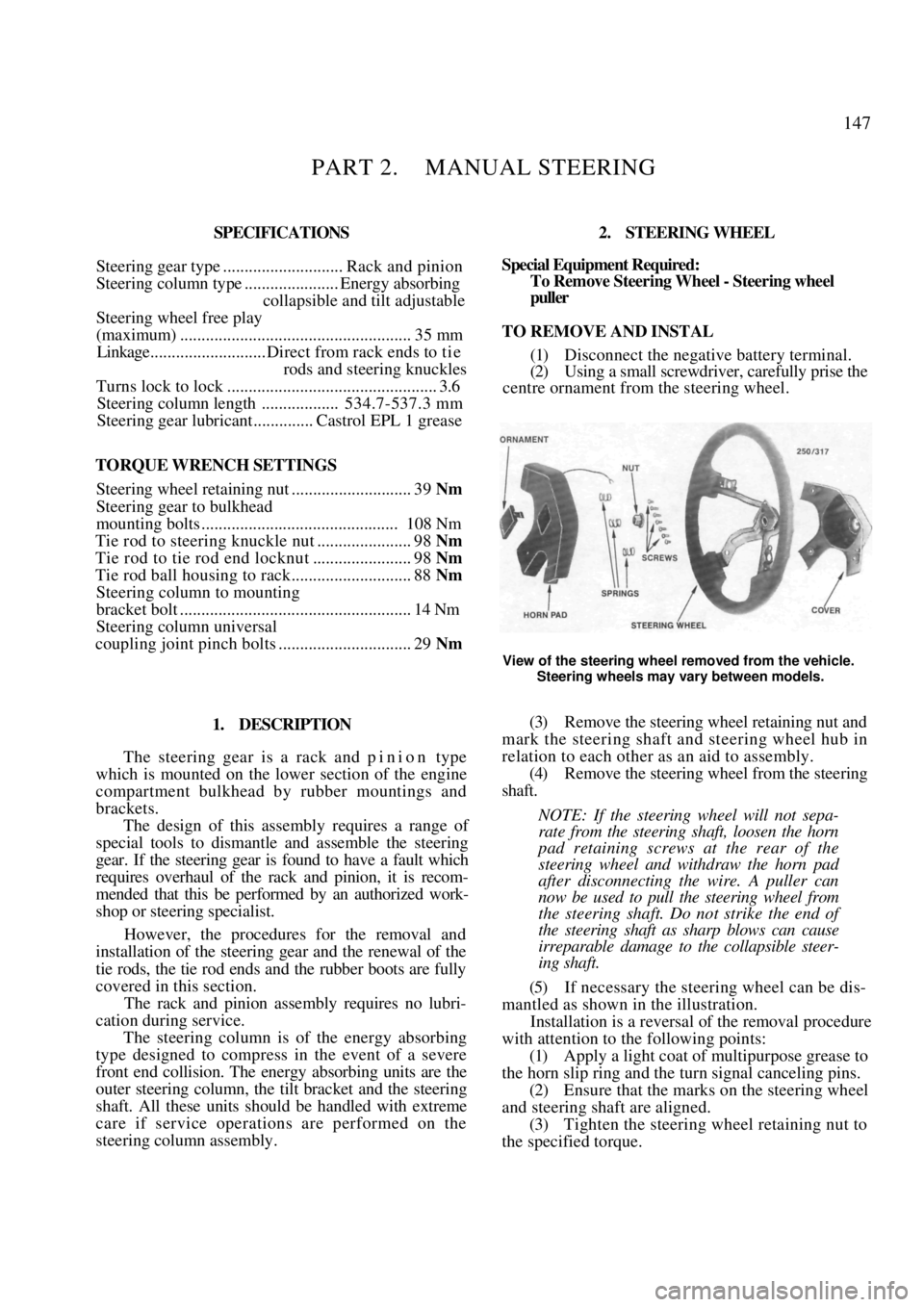
View of the steering wheel removed from the vehicle.
Steering wheels may vary between models.
1. DESCRIPTION
The steering gear is a rack and p i n i o n type
which is mounted on the lower section of the engine
compartment bulkhead by rubber mountings and
brackets.
The design of this assembly requires a range of
special tools to dismantle and assemble the steering
gear. If the steering gear is found to have a fault which
requires overhaul of the rack and pinion, it is recom-
mended that this be performed by an authorized work-
shop or steering specialist.
However, the procedures for the removal and
installation of the steering gear and the renewal of the
tie rods, the tie rod ends and the rubber boots are fully
covered in this section.
The rack and pinion assembly requires no lubri-
cation during service.
The steering column is of the energy absorbing
type designed to compress in the event of a severe
front end collision. The energy absorbing units are the
outer steering column, the tilt bracket and the steering
shaft. All these units shoul d be handled with extreme
care if service operations are performed on the
steering column assembly.
(3) Remove the steering wh eel retaining nut and
mark the steering shaft and steering wheel hub in
relation to each other as an aid to assembly.
(4) Remove the steering wheel from the steering
shaft.
NOTE: If the steering wheel will not sepa-
rate from the steering shaft, loosen the horn
pad retaining screws at the rear of the
steering wheel and withdraw the horn pad
after disconnecting the wire. A puller can
now be used to pull the steering wheel from
the steering shaft. Do not strike the end of
the steering shaft as sharp blows can cause
irreparable damage to the collapsible steer-
ing shaft.
(5) If necessary the steering wheel can be dis-
mantled as shown in the illustration.
Installation is a reversal of the removal procedure
with attention to the following points:
(1) Apply a light coat of multipurpose grease to
the horn slip ring and the turn signal canceling pins.
(2) Ensure that the marks on the steering wheel
and steering shaf t are aligned.
(3) Tighten the steering wheel retaining nut to
the specified torque.
Page 148 of 238
148 Steering — Part 2
3. STEERING COLUMN
Special Equipment Required:
To Remove Steering Wheel — Steering wheel
puller
TO REMOVE AND INSTAL
(1) Disconnect the negative battery terminal.
(2) Working in the engine compartment, mark
the relationship between the steering shaft universal
coupling joint and the steering gear pinion shaft. (3) Remove the pinch bolts from the universal
joint. (4) Working inside the vehi cle, remove the steer-
ing wheel as previously described. (5) Remove the steering column shroud screws,
unclip the lower and upper covers and remove them
from the steering column. (6) Disconnect all the steering column wiring
connectors. (7) Remove the lower trim from underneath the
steering column.
(8) Fold back the insulator and remove the nuts
from the steering colu mn floor bracket.
(9) Remove the nuts from the lower steering
column bracket. (10) Remove the bolts from the tilt bracket
assembly. (11) Maneuver the steering column from the
vehicle.
Installation is a reversal of the removal procedure
with attention to the following points:
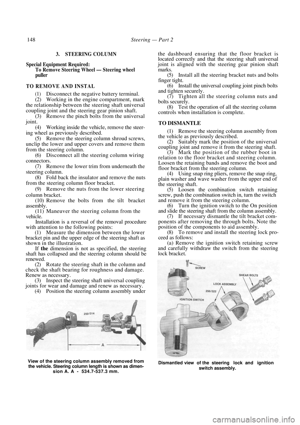
(1) Measure the dimension between the lower
bracket pin and the upper edge of the steering shaft as
shown in the illustration.
If the dimension is not as specified, the steering
shaft has collapsed and the steering column should be
renewed.
(2) Rotate the steering shaft in the column and
check the shaft bearing for roughness and damage.
Renew as necessary. (3) Inspect the steering shaft universal coupling
joints for wear and damage and renew as necessary. (4) Position the steering column assembly under
the dashboard ensuring that the floor bracket is
located correctly and that the steering shaft universal
joint is aligned with the steering gear pinion shaft
marks.
(5) Install all the steering bracket nuts and bolts
finger tight. (6) Install the universal coupling joint pinch bolts
and tighten securely.
(7) Tighten all the stee ring column nuts and
bolts securely. (8) Test the operation of all the steering column
controls when installation is complete.
TO DISMANTLE
(1) Remove the steering column assembly from
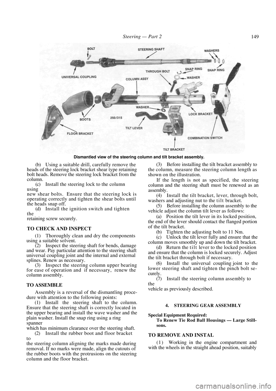
the vehicle as previously described. (2) Suitably mark the position of the universal
coupling joint and remove it from the steering shaft. (3) Mark the position of the rubber boot in
relation to the floor bracket and steering column.
Loosen the retaining bands and remove the boot and
floor bracket from th e steering column.
(4) Using snap ring pliers, remove the snap ring,
plain washer and wave washer from the upper end of
the steering shaft. (5) Loosen the combination switch retaining
screw, push the combination switch in, turn the switch
and remove it from the steering column. (6) Turn the ignition switch to the On position
and slide the steering shaft from the column assembly. (7) If necessary dismantle the tilt bracket com-
ponents after removing the through bolts. Note the
position of the components to aid assembly. (8) To remove and install the steering lock pro-
ceed as follows: (a) Remove the ignition switch retaining screw
and carefully withdraw the switch from the steering
lock bracket.
View of the steering column assembly removed from
the vehicle. Steering column length is shown as dimen- sion A. A - 534.7-537.3 mm. Dismantled view of the steering lock and ignition
switch assembly.
Page 149 of 238
Steering — Part 2 149
Dismantled view of the steering column and tilt bracket assembly.
(b) Using a suitable drill, carefully remove the
heads of the steering lock br acket shear type retaining
bolt heads. Remove the steering lock bracket from the
column.
(c) Install the steering lock to the column
using
new shear bolts. Ensure that the steering lock is
operating correctly and tigh ten the shear bolts until
the heads snap off.
(d) Install the ignition switch and tighten
the
retaining screw securely.
TO CHECK AND INSPECT
(1) Thoroughly clean and dry the components
using a suitable solvent.
(2) Inspect the steering shaft for bends, damage
and wear. Pay particular attention to the steering shaft
universal coupling joint and the internal and external
splines. Renew as necessary. (3) Inspect the steering column upper bearing
for ease of operation and if necessary, renew the
column assembly.
TO ASSEMBLE
Assembly is a reversal of the dismantling proce-
dure with attention to the following points:
(1) Install the steering shaft to the column.
Ensure that the steering shaft is correctly located in
the upper bearing and insta ll the wave washer and the
plain washer. Install the snap ring using a ring
spanner
which has minimum clearan ce over the steering shaft.
(2) Install the rubber boot and floor bracket
to
the steering column aligning the marks made during
removal. If no marks were made, align the cutouts of
the rubber boots with the protrusions on the steering
column and the floor bracket. (3) Before installing the tilt bracket assembly to
the column, measure the steering column length as
shown on the illustration.
If the length is not as specified, the steering
column and the steering shaft must be renewed as an
assembly.
(4) Install the tilt bracket, lever, through bolt,
washers and adjusting nu t to the t i l t bracket.
(5) Before installing the column assembly to the
vehicle adjust the column tilt lever as follows:
(a) Position the tilt lever in its locked position,
the end of the lever should contact the flanged portion
of the tilt bracket.
(b) Tighten the adjusting bolt to 11 Nm.
(c) Unlock the tilt lever fully and ensure that the
column moves smoothly up and down the tilt bracket. (d) Return the tilt lever to the locked position
and ensure that the column is locked securely. Adjust
the tilt bracket thro ugh bolt if necessary.
(6) Install the universal coupling joint to the
lower steering shaft and tighten the pinch bolt se-
curely.
(7) Install the steering column assembly to
the
vehicle as previously described.
4. STEERING GEAR ASSEMBLY
Special Equipment Required:
To Renew Tie Rod Ball Housings — Large Still-
sons.
TO REMOVE AND INSTAL
( 1 ) Working in the engine compartment and
with the wheels in the straight ahead position, suitably