NISSAN QASHQAI 2016 Owner´s Manual
Manufacturer: NISSAN, Model Year: 2016, Model line: QASHQAI, Model: NISSAN QASHQAI 2016Pages: 338, PDF Size: 4.87 MB
Page 231 of 338
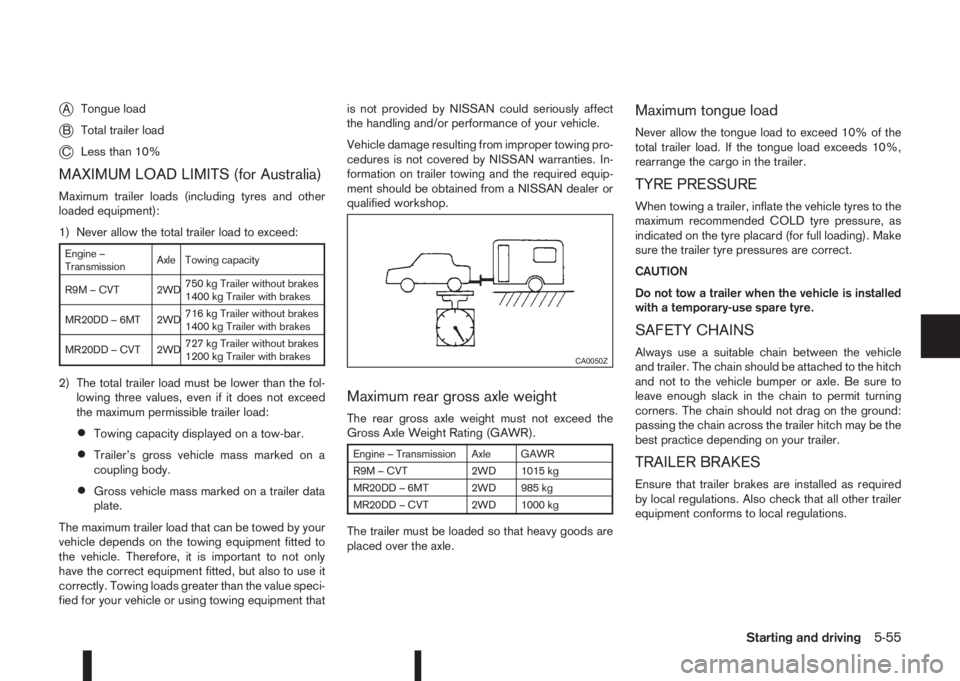
jATongue load
jBTotal trailer load
jCLess than 10%
MAXIMUM LOAD LIMITS (for Australia)
Maximum trailer loads (including tyres and other
loaded equipment):
1) Never allow the total trailer load to exceed:
Engine –
TransmissionAxle Towing capacity
R9M – CVT 2WD750 kg Trailer without brakes
1400 kg Trailer with brakes
MR20DD – 6MT 2WD716 kg Trailer without brakes
1400 kg Trailer with brakes
MR20DD – CVT 2WD727 kg Trailer without brakes
1200 kg Trailer with brakes
2) The total trailer load must be lower than the fol-
lowing three values, even if it does not exceed
the maximum permissible trailer load:
•Towing capacity displayed on a tow-bar.
•Trailer’s gross vehicle mass marked on a
coupling body.
•Gross vehicle mass marked on a trailer data
plate.
The maximum trailer load that can be towed by your
vehicle depends on the towing equipment fitted to
the vehicle. Therefore, it is important to not only
have the correct equipment fitted, but also to use it
correctly. Towing loads greater than the value speci-
fied for your vehicle or using towing equipment thatis not provided by NISSAN could seriously affect
the handling and/or performance of your vehicle.
Vehicle damage resulting from improper towing pro-
cedures is not covered by NISSAN warranties. In-
formation on trailer towing and the required equip-
ment should be obtained from a NISSAN dealer or
qualified workshop.
Maximum rear gross axle weight
The rear gross axle weight must not exceed the
Gross Axle Weight Rating (GAWR).
Engine – Transmission Axle GAWR
R9M – CVT 2WD 1015 kg
MR20DD – 6MT 2WD 985 kg
MR20DD – CVT 2WD 1000 kg
The trailer must be loaded so that heavy goods are
placed over the axle.
Maximum tongue load
Never allow the tongue load to exceed 10% of the
total trailer load. If the tongue load exceeds 10%,
rearrange the cargo in the trailer.
TYRE PRESSURE
When towing a trailer, inflate the vehicle tyres to the
maximum recommended COLD tyre pressure, as
indicated on the tyre placard (for full loading). Make
sure the trailer tyre pressures are correct.
CAUTION
Do not tow a trailer when the vehicle is installed
with a temporary-use spare tyre.
SAFETY CHAINS
Always use a suitable chain between the vehicle
and trailer. The chain should be attached to the hitch
and not to the vehicle bumper or axle. Be sure to
leave enough slack in the chain to permit turning
corners. The chain should not drag on the ground:
passing the chain across the trailer hitch may be the
best practice depending on your trailer.
TRAILER BRAKES
Ensure that trailer brakes are installed as required
by local regulations. Also check that all other trailer
equipment conforms to local regulations.
CA0050Z
Starting and driving5-55
Page 232 of 338
TRAILER DETECTION (where fitted)
When towing a trailer and the turn signal switch is
used, the electrical system of the vehicle will detect
an additional electrical load of the trailer lighting. As
a result, the trailer direction indicator light comes
on.
INSTALLATION OF COUPLING
DEVICE (except for Australia)
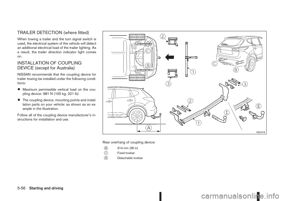
NISSAN recommends that the coupling device for
trailer towing be installed under the following condi-
tions:
•Maximum permissible vertical load on the cou-
pling device: 981 N (100 kg, 221 lb)
•The coupling device, mounting points and instal-
lation parts on your vehicle: as shown as an ex-
ample in the illustration.
Follow all of the coupling device manufacturer’s in-
structions for installation and use.
Rear overhang of coupling device:
jA 914 mm (36 in)
jI Fixed towbar
jII Detachable towbar
NSD478
5-56Starting and driving
Page 233 of 338
When leaving your vehicle unoccupied:
•Always remove the ignition key and take it with
you – even in your own garage.
•Always remove the ignition key or Intelligent Key
(where fitted) and take it with you – even in your
own garage.
•Close all windows completely and lock all doors.
•Always park your vehicle where it can be seen.
At night, park in a well lit area.
•If the vehicle is equipped with an alarm or immo-
bilization device, use it – even for short periods.
•Do not leave children and pets in the vehicle
unattended.
•Do not leave valuables on view to tempt a thief.
Always take your valuables with you. If you must
leave something in your vehicle, lock it in the lug-
gage compartment or hide it out of sight.
•Do not leave the vehicle documents in your ve-
hicle. In the unfortunate event of your vehicle
being stolen, the documents will only help a thief
to sell the vehicle.
•Do not leave articles on a roof rack as they are
particularly vulnerable. If possible, remove them
from the rack and lock them inside the vehicle.
•Do not leave the spare key in the vehicle – keep
it in a safe place at home.
•Do not leave the spare key or Intelligent Key in
the vehicle – keep it in a safe place at home.
•Do not leave a note of your vehicle’s key number
in the vehicle. A thief may break into the vehicle,
note the key number and return with a new key
and drive the vehicle.WARNING
•If the engine is not running or is turned off
while driving, the power assistance for the
steering will not work. The steering will be
harder to operate.
•When the electric power steering warning light
illuminates with the engine running, the power
assistance for the steering will cease opera-
tion. You will still have control of the vehicle
but the steering will be harder to operate.
The electric power steering system is designed to
provide power assistance while driving to allow you
to operate the steering wheel with light force.
The steering effort can be set to [Normal] or [Sport]
in the vehicle information display under the heading
[Driver assistance]. (See “[Driver assistance]” in the
“2. Instruments and controls” section.)
NOTE
When the steering wheel is operated repeatedly
or continuously while parking or driving at a very
low speed, the power assistance for the steering
wheel will be reduced. This is to prevent over-
heating of the electric power steering system and
protect it from becoming damaged. While the
power assistance is reduced, steering wheel op-
eration will become heavy. When the tempera-
ture of the electric power steering system de-
creases, the power assistance level will return to
normal. Avoid repeating such steering wheel op-
erations that could cause the electric power
steering system to overheat.
VEHICLE SECURITY ELECTRIC POWER STEERING
SYSTEM
Starting and driving5-57
Page 234 of 338
You may hear a sound when the steering wheel
is operated quickly. However, this is not a mal-
function.
If the electric power steering warning light
illu-
minates while the engine is running, it may indicate
the electric power steering system is not functioning
properly and may need servicing. Have the electric
power steering system checked by a NISSAN dealer
or qualified workshop. (See “ Power steering warn-
ing light” in the “2. Instruments and controls” sec-
tion.)
When the electric power steering warning light illu-
minates with the engine running, the power assis-
tance for the steering will cease operation. You will
still have control of the vehicle. However, greater
steering effort is needed, especially in sharp turns
and at low speeds.The brake system has two separate hydraulic cir-
cuits. If one circuit malfunctions, two wheels will still
have braking ability.BRAKE PRECAUTIONS
Vacuum assisted brake
The brake booster aids braking by using engine
vacuum or vacuum from an engine-driven pump. If
the engine stops or the drive belt is broken, you can
stop the vehicle by depressing the brake pedal.
However, greater foot pressure on the brake pedal
will be required to stop the vehicle and the stopping
distance will be longer.
Wet brakes
When the vehicle is washed or driven through wa-
ter, the brakes may get wet. As a result, your brak-
ing distance will be longer and the vehicle may pull
to one side during braking.
To dry brakes, drive the vehicle at a safe speed
while lightly pressing the brake pedal to heat up the
brakes. Do this until the brakes return to normal.
Avoid driving the vehicle at high speeds until the
brakes function correctly.
Using the brakes
Avoid resting your foot on the brake pedal while
driving. This will overheat the brakes, wear out the
brake linings and pads faster and reduce fuel
economy performance.
To help reduce brake wear and to prevent the brakes
from overheating, reduce speed and shift to a lower
gear before going down a slope or long downhillgradient. Overheated brakes may reduce braking
performance and could result in loss of vehicle con-
trol.
CAUTION
While driving on a slippery surface, be careful
when braking, accelerating or downshifting.
Abrupt braking actions or sudden acceleration
could cause the wheels to skid and result in an
accident.
Be aware that brakes will fade if repeated heavy
brake applications are made.
Driving uphill
When starting on a steep gradient, it is sometimes
difficult to operate the brake or both the brake and
clutch (MT models). Use the parking brake to hold
the vehicle. Do not slip the clutch (MT models).
When ready to start, make sure that the shift lever is
in an appropriate forward or reverse driving posi-
tion, slowly release the parking brake while depress-
ing the accelerator pedal and releasing the clutch
(MT models) or depressing the accelerator pedal
(XTRONIC transmission models). If your vehicle has
an electric parking brake, this will automatically re-
lease when you depress the accelerator pedal and
release the clutch (MT models) or depress the ac-
celerator pedal (XTRONIC transmission models).
BRAKE SYSTEM
5-58Starting and driving
Page 235 of 338
Driving downhill
The engine braking action is effective for controlling
the vehicle while descending hills.
The shift lever (MT models) should be placed in a
gear position low enough to obtain sufficient engine
braking.
For XTRONIC transmission models, a low gear po-
sition in the manual shift mode, low enough to obtain
sufficient engine braking, should be selected.WARNING
•The Anti-lock Braking System (ABS) is a so-
phisticated device, but it cannot prevent acci-
dents resulting from careless or dangerous
driving techniques. It can help maintain ve-
hicle control during braking on slippery sur-
faces. Remember that stopping distances on
slippery surfaces will be longer than on nor-
mal surfaces even with ABS. Stopping dis-
tances may also be longer on rough, gravel or
snow covered roads, or if you are using snow
chains. Always maintain a safe distance from
the vehicle in front of you. Ultimately, the
driver is responsible for safety.
•Tyre type and condition may also affect brak-
ing effectiveness.
– When replacing tyres, install the specified
size of tyres on all four wheels.
– When installing a spare tyre, make sure
that it is the proper size and type as speci-
fied on the tyre placard. (See “Vehicle
identification” in the “9. Technical
information” section.)
– For detailed information, see “Wheels and
tyres” in the “8. Maintenance and
do-it-yourself” section.
The Anti-lock Braking System (ABS) controls the
brakes so the wheels do not lock during hard brak-
ing or when braking on slippery surfaces. The sys-
tem detects the rotation speed at each wheel and
varies the brake fluid pressure to prevent each wheelfrom locking and sliding. By preventing each wheel
from locking, the system helps the driver maintain
steering control and helps to minimise swerving and
spinning on slippery surfaces.
USING SYSTEM
Depress the brake pedal and hold it down. Depress
the brake pedal with firm steady pressure, but do
not pump the brakes. The ABS will operate to pre-
vent the wheels from locking up. Steer the vehicle to
avoid obstacles.
WARNING
Do not pump the brake pedal. Doing so may re-
sult in increased stopping distances.
SELF-TEST FEATURE
The ABS includes electronic sensors, electric
pumps, hydraulic solenoids and a computer. The
computer has a built-in diagnostic feature that tests
the system each time you start the engine and move
the vehicle at a low speed in forward or reverse.
When the self-test occurs, you may hear a “clunk”
noise and/or feel a pulsation in the brake pedal. This
is normal and does not indicate a malfunction. If the
computer senses a malfunction, it switches the ABS
off and illuminates the ABS warning light on the
instrument panel. The brake system then operates
normally, but without anti-lock assistance.
If the ABS warning light illuminates during the self-
test or while driving, have the vehicle checked by a
NISSAN dealer or qualified workshop.
ANTI-LOCK BRAKING SYSTEM
(ABS)
Starting and driving5-59
Page 236 of 338
NORMAL OPERATION
The ABS operates at speeds above 5 to 10 km/h (3
to 6 MPH). The speed varies according to road con-
ditions.
When the ABS senses that one or more wheels are
close to locking up, the actuator rapidly applies and
releases hydraulic pressure. This action is similar to
pumping the brakes very quickly. You may feel a
pulsation in the brake pedal and hear a noise from
under the bonnet or feel a vibration from the actua-
tor when it is operating. This is normal and indicates
that the ABS is operating properly. However, the
pulsation may indicate that road conditions are haz-
ardous and extra care is required while driving.When accelerating, driving on slippery surfaces or
suddenly avoiding obstacles on roads, the vehicle
might swerve or slip. The Electronic Stability Pro-
gramme (ESP) system continuously monitors and
compares the driver’s intended speed and the travel
direction. The system adjusts wheel brake pressure
and engine torque to assist in improving vehicle sta-
bility.
•When the ESP system is operating, the “SLIP”
indicator light () in the combination meter
blinks.
•When only the traction control (TCS) system in
the ESP system is operating, the “SLIP” indica-
tor light (
) in the combination meter will also
blink.
•If the “SLIP” indicator light () blinks, the road
conditions are slippery. Be sure to drive care-
fully. See “Warning/indicator lights and audible
reminders” in the “2. Instruments and controls”
section.
•Indicator light
If a malfunction occurs in the system, the “SLIP”
indicator light (
) will come on in the combina-
tion meter.
As long as these indicator lights are on, the trac-
tion control function is cancelled.
The ESP system uses Active Brake Limited Slip
(ABLS) system to improve vehicle traction. The Ac-
tive Brake Limited Slip (ABLS) system works when
one of the driving wheels is spinning on a slipperysurface. The Active Brake Limited Slip (ABLS) sys-
tem, brakes the spinning wheel to distribute the driv-
ing power to the other driving wheel.
If the vehicle is operated with the ESP system turned
off, all ESP and TCS functions will be turned off.
The Active Brake Limited Slip (ABLS) system and
ABS will still operate with the ESP system off. If the
Active Brake Limited Slip (ABLS) system is acti-
vated, the “SLIP” indicator light (
) will blink and
you may hear a clunk noise and/or feel a pulsation in
the brake pedal. This is normal and does not indi-
cate a malfunction.
While the ESP system is operating, you may feel a
pulsation in the brake pedal and hear a noise or
vibration from under the bonnet. This is normal and
indicates that the ESP system is working properly.
The ESP computer has a built in diagnostic feature
that tests the system each time the engine is started
and the vehicle moves forwards or reverses at a
slow speed. When the self-test occurs, you may
hear a clunk noise and/or feel a pulsation in the
brake pedal. This is normal and is not an indication
of a malfunction.
WARNING
•The ESP system is designed to help improve
driving stability but does not prevent accidents
caused by abrupt steering operation at high
speeds, or careless or dangerous driving
techniques. Reduce vehicle speed and be es-
pecially careful when driving and cornering on
slippery surfaces. Always drive carefully.
ELECTRONIC STABILITY PROGRAMME (ESP) SYSTEM (where fitted)
5-60Starting and driving
Page 237 of 338
•If engine related parts, such as a muffler, are
not standard equipment or are extremely de-
teriorated, the “SLIP” indicator light (
) may
illuminate.
•If brake related parts, such as brake pads,
rotors and callipers, are not standard equip-
ment or are extremely deteriorated, the ESP
system may not operate properly and the
“SLIP” indicator light (
) may illuminate.
•Do not modify the vehicle’s suspension. If
suspension parts, such as shock absorbers,
struts, springs, stabiliser bars and bushings,
are not NISSAN-approved or are extremely
deteriorated, the ESP system may not oper-
ate properly. This could adversely affect ve-
hicle handling performance and the “SLIP” in-
dicator light (
) may illuminate.
•When driving on extremely inclined surfaces,
such as higher banked corners, the ESP sys-
tem may not operate properly and the “SLIP”
indicator light (
) may illuminate. Do not
drive on these types of roads. If ESP OFF indi-
cator light
does illuminate after driving
on extreme surfaces, restart the engine to re-
set the ESP system.
•If wheels or tyres other than the
recommended ones are used, the ESP sys-
tem may not operate properly and the “SLIP”
indicator light (
) may illuminate.
•The ESP system is not a substitute for winter
tyres or snow chains on a snow covered road.NOTE
•The ESP system should be switched on under
normal circumstances although it may be ad-
vantageous to switch off the ESP system to
allow wheelspin under the following condi-
tions:
– When driving in deep snow or mud.
– When trying to rock a vehicle free that is
stuck in snow.
– When driving with snow chains.
•If the ESP system has been switched off, drive
carefully with reduced speed. When road con-
ditions allow, ESP should be switched back
on.
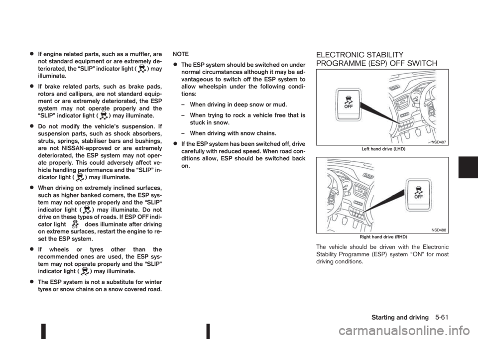
ELECTRONIC STABILITY
PROGRAMME (ESP) OFF SWITCH
The vehicle should be driven with the Electronic
Stability Programme (ESP) system “ON” for most
driving conditions.
NSD487Left hand drive (LHD)
NSD488Right hand drive (RHD)
Starting and driving5-61
Page 238 of 338
If the vehicle is stuck in mud or snow, the ESP sys-
tem reduces the engine output to decrease wheel
spin. The engine speed will be reduced even if the
accelerator is depressed to the floor. If maximum
engine power is needed to free a stuck vehicle, turn
the ESP system off.
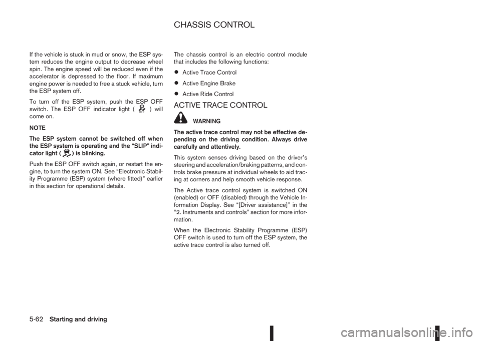
To turn off the ESP system, push the ESP OFF
switch. The ESP OFF indicator light (
) will
come on.
NOTE
The ESP system cannot be switched off when
the ESP system is operating and the “SLIP” indi-
cator light (
) is blinking.
Push the ESP OFF switch again, or restart the en-
gine, to turn the system ON. See “Electronic Stabil-
ity Programme (ESP) system (where fitted)” earlier
in this section for operational details.The chassis control is an electric control module
that includes the following functions:
•Active Trace Control
•Active Engine Brake
•Active Ride Control
ACTIVE TRACE CONTROL
WARNING
The active trace control may not be effective de-
pending on the driving condition. Always drive
carefully and attentively.
This system senses driving based on the driver’s
steering and acceleration/braking patterns, and con-
trols brake pressure at individual wheels to aid trac-
ing at corners and help smooth vehicle response.
The Active trace control system is switched ON
(enabled) or OFF (disabled) through the Vehicle In-
formation Display. See “[Driver assistance]” in the
“2. Instruments and controls” section for more infor-
mation.
When the Electronic Stability Programme (ESP)
OFF switch is used to turn off the ESP system, the
active trace control is also turned off.
CHASSIS CONTROL
5-62Starting and driving
Page 239 of 338
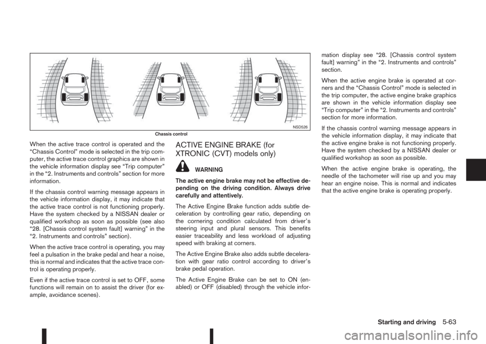
When the active trace control is operated and the
“Chassis Control” mode is selected in the trip com-
puter, the active trace control graphics are shown in
the vehicle information display see “Trip computer”
in the “2. Instruments and controls” section for more
information.
If the chassis control warning message appears in
the vehicle information display, it may indicate that
the active trace control is not functioning properly.
Have the system checked by a NISSAN dealer or
qualified workshop as soon as possible (see also
“28. [Chassis control system fault] warning” in the
“2. Instruments and controls” section).
When the active trace control is operating, you may
feel a pulsation in the brake pedal and hear a noise,
this is normal and indicates that the active trace con-
trol is operating properly.
Even if the active trace control is set to OFF, some
functions will remain on to assist the driver (for ex-
ample, avoidance scenes).ACTIVE ENGINE BRAKE (for
XTRONIC (CVT) models only)
WARNING
The active engine brake may not be effective de-
pending on the driving condition. Always drive
carefully and attentively.
The Active Engine Brake function adds subtle de-
celeration by controlling gear ratio, depending on
the cornering condition calculated from driver’s
steering input and plural sensors. This benefits
easier traceability and less workload of adjusting
speed with braking at corners.
The Active Engine Brake also adds subtle decelera-
tion with gear ratio control according to driver’s
brake pedal operation.
The Active Engine Brake can be set to ON (en-
abled) or OFF (disabled) through the vehicle infor-mation display see “28. [Chassis control system
fault] warning” in the “2. Instruments and controls”
section.
When the active engine brake is operated at cor-
ners and the “Chassis Control” mode is selected in
the trip computer, the active engine brake graphics
are shown in the vehicle information display see
“Trip computer” in the “2. Instruments and controls”
section for more information.
If the chassis control warning message appears in
the vehicle information display, it may indicate that
the active engine brake is not functioning properly.
Have the system checked by a NISSAN dealer or
qualified workshop as soon as possible.
When the active engine brake is operating, the
needle of the tachometer will rise up and you may
hear an engine noise. This is normal and indicates
that the active engine brake is operating properly.
NSD526Chassis control
Starting and driving5-63
Page 240 of 338
ACTIVE RIDE CONTROL
This system senses upper body motion based on
wheel speed information and controls engine torque
(MR20DD engines only) and four wheel brake pres-
sure to enhance ride comfort in an effort to restrain
uncomfortable upper body movement. This system
come into effect above 40 km/h (25 MPH).
When the ESP OFF switch is used to turn off the
ESP system, the active ride control is also turned
off.
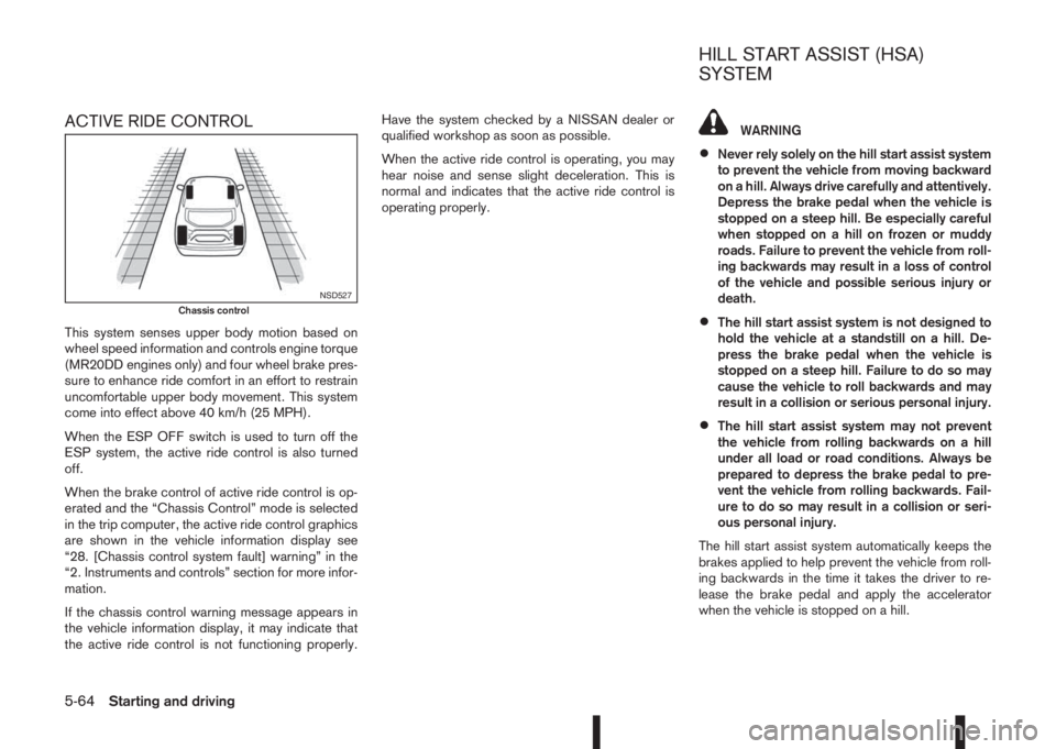
When the brake control of active ride control is op-
erated and the “Chassis Control” mode is selected
in the trip computer, the active ride control graphics
are shown in the vehicle information display see
“28. [Chassis control system fault] warning” in the
“2. Instruments and controls” section for more infor-
mation.
If the chassis control warning message appears in
the vehicle information display, it may indicate that
the active ride control is not functioning properly.Have the system checked by a NISSAN dealer or
qualified workshop as soon as possible.
When the active ride control is operating, you may
hear noise and sense slight deceleration. This is
normal and indicates that the active ride control is
operating properly.
WARNING
•Never rely solely on the hill start assist system
to prevent the vehicle from moving backward
on a hill. Always drive carefully and attentively.
Depress the brake pedal when the vehicle is
stopped on a steep hill. Be especially careful
when stopped on a hill on frozen or muddy
roads. Failure to prevent the vehicle from roll-
ing backwards may result in a loss of control
of the vehicle and possible serious injury or
death.
•The hill start assist system is not designed to
hold the vehicle at a standstill on a hill. De-
press the brake pedal when the vehicle is
stopped on a steep hill. Failure to do so may
cause the vehicle to roll backwards and may
result in a collision or serious personal injury.
•The hill start assist system may not prevent
the vehicle from rolling backwards on a hill
under all load or road conditions. Always be
prepared to depress the brake pedal to pre-
vent the vehicle from rolling backwards. Fail-
ure to do so may result in a collision or seri-
ous personal injury.
The hill start assist system automatically keeps the
brakes applied to help prevent the vehicle from roll-
ing backwards in the time it takes the driver to re-
lease the brake pedal and apply the accelerator
when the vehicle is stopped on a hill.
NSD527Chassis control
HILL START ASSIST (HSA)
SYSTEM
5-64Starting and driving