stop start NISSAN TEANA 2008 Service Manual
[x] Cancel search | Manufacturer: NISSAN, Model Year: 2008, Model line: TEANA, Model: NISSAN TEANA 2008Pages: 5121, PDF Size: 69.03 MB
Page 3694 of 5121

PWC-64
< ECU DIAGNOSIS >
BCM (BODY CONTROL MODULE)
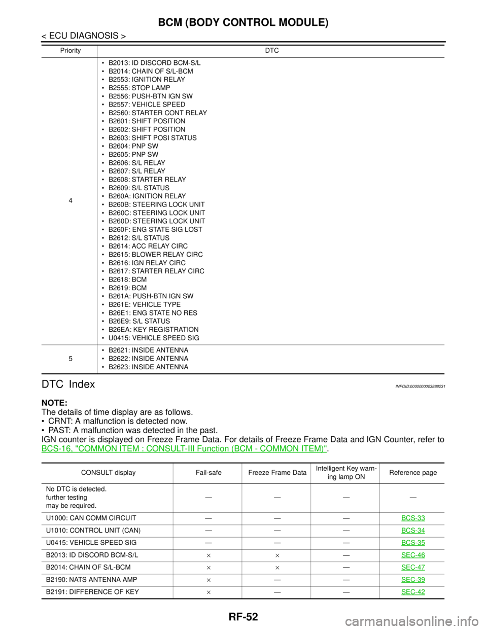
DTC Index
INFOID:0000000003888239
NOTE:
The details of time display are as follows.
CRNT: A malfunction is detected now.
PAST: A malfunction was detected in the past.
IGN counter is displayed on Freeze Frame Data. For details of Freeze Frame Data and IGN Counter, refer to
BCS-16, "
COMMON ITEM : CONSULT-III Function (BCM - COMMON ITEM)".
4 B2013: ID DISCORD BCM-S/L
B2014: CHAIN OF S/L-BCM
B2553: IGNITION RELAY
B2555: STOP LAMP
B2556: PUSH-BTN IGN SW
B2557: VEHICLE SPEED
B2560: STARTER CONT RELAY
B2601: SHIFT POSITION
B2602: SHIFT POSITION
B2603: SHIFT POSI STATUS
B2604: PNP SW
B2605: PNP SW
B2606: S/L RELAY
B2607: S/L RELAY
B2608: STARTER RELAY
B2609: S/L STATUS
B260A: IGNITION RELAY
B260B: STEERING LOCK UNIT
B260C: STEERING LOCK UNIT
B260D: STEERING LOCK UNIT
B260F: ENG STATE SIG LOST
B2612: S/L STATUS
B2614: ACC RELAY CIRC
B2615: BLOWER RELAY CIRC
B2616: IGN RELAY CIRC
B2617: STARTER RELAY CIRC
B2618: BCM
B2619: BCM
B261A: PUSH-BTN IGN SW
B261E: VEHICLE TYPE
B26E1: ENG STATE NO RES
B26E9: S/L STATUS
B26EA: KEY REGISTRATION
U0415: VEHICLE SPEED SIG
5 B2621: INSIDE ANTENNA
B2622: INSIDE ANTENNA
B2623: INSIDE ANTENNA Priority DTC
CONSULT display Fail-safe Freeze Frame DataIntelligent Key warn-
ing lamp ONReference page
No DTC is detected.
further testing
may be required.————
U1000: CAN COMM CIRCUIT — — —BCS-33
U1010: CONTROL UNIT (CAN) — — —BCS-34
U0415: VEHICLE SPEED SIG — — —BCS-35
B2013: ID DISCORD BCM-S/L××—SEC-46
B2014: CHAIN OF S/L-BCM××—SEC-47
B2190: NATS ANTENNA AMP×——SEC-39
B2191: DIFFERENCE OF KEY×——SEC-42
Page 3695 of 5121

BCM (BODY CONTROL MODULE)
PWC-65
< ECU DIAGNOSIS >
C
D
E
F
G
H
I
J
L
MA
B
PWC
N
O
P
B2192: ID DISCORD BCM-ECM×——SEC-43
B2193: CHAIN OF BCM-ECM×——SEC-45
B2553: IGNITION RELAY —×—PCS-49
B2555: STOP LAMP —×—SEC-50
B2556: PUSH-BTN IGN SW —××SEC-52
B2557: VEHICLE SPEED×××SEC-54
B2560: STARTER CONT RELAY×××SEC-55
B2562: LOW VOLTAGE —×—BCS-36
B2601: SHIFT POSITION×××SEC-56
B2602: SHIFT POSITION×××SEC-59
B2603: SHIFT POSI STATUS×××SEC-61
B2604: PNP SW×××SEC-64
B2605: PNP SW×××SEC-67
B2606: S/L RELAY×××SEC-69
B2607: S/L RELAY×××SEC-70
B2608: STARTER RELAY×××SEC-72
B2609: S/L STATUS×××SEC-74
B260A: IGNITION RELAY×××PCS-51
B260B: STEERING LOCK UNIT —××SEC-78
B260C: STEERING LOCK UNIT —××SEC-79
B260D: STEERING LOCK UNIT —××SEC-80
B260F: ENG STATE SIG LOST×××SEC-81
B2612: S/L STATUS×××SEC-85
B2614: ACC RELAY CIRC —××PCS-53
B2615: BLOWER RELAY CIRC —××PCS-55
B2616: IGN RELAY CIRC —××PCS-57
B2617: STARTER RELAY CIRC×××SEC-89
B2618: BCM×××PCS-59
B2619: BCM×××SEC-91
B261A: PUSH-BTN IGN SW —××SEC-92
B261E: VEHICLE TYPE××× (Turn ON for 15
seconds)SEC-95
B2621: INSIDE ANTENNA —×—DLK-50
B2622: INSIDE ANTENNA —×—DLK-52
B2623: INSIDE ANTENNA —×—DLK-54
B26E1: ENG STATE NO RES×××SEC-82
B26E9: S/L STATUS××× (Turn ON for 15
seconds)SEC-83
B26EA: KEY REGISTRATION —×× (Turn ON for 15
seconds)SEC-84
CONSULT display Fail-safe Freeze Frame DataIntelligent Key warn-
ing lamp ONReference page
Page 3783 of 5121
RF-52
< ECU DIAGNOSIS >
BCM (BODY CONTROL MODULE)
DTC Index
INFOID:0000000003888231
NOTE:
The details of time display are as follows.
CRNT: A malfunction is detected now.
PAST: A malfunction was detected in the past.
IGN counter is displayed on Freeze Frame Data. For details of Freeze Frame Data and IGN Counter, refer to
BCS-16, "
COMMON ITEM : CONSULT-III Function (BCM - COMMON ITEM)".
4 B2013: ID DISCORD BCM-S/L
B2014: CHAIN OF S/L-BCM
B2553: IGNITION RELAY
B2555: STOP LAMP
B2556: PUSH-BTN IGN SW
B2557: VEHICLE SPEED
B2560: STARTER CONT RELAY
B2601: SHIFT POSITION
B2602: SHIFT POSITION
B2603: SHIFT POSI STATUS
B2604: PNP SW
B2605: PNP SW
B2606: S/L RELAY
B2607: S/L RELAY
B2608: STARTER RELAY
B2609: S/L STATUS
B260A: IGNITION RELAY
B260B: STEERING LOCK UNIT
B260C: STEERING LOCK UNIT
B260D: STEERING LOCK UNIT
B260F: ENG STATE SIG LOST
B2612: S/L STATUS
B2614: ACC RELAY CIRC
B2615: BLOWER RELAY CIRC
B2616: IGN RELAY CIRC
B2617: STARTER RELAY CIRC
B2618: BCM
B2619: BCM
B261A: PUSH-BTN IGN SW
B261E: VEHICLE TYPE
B26E1: ENG STATE NO RES
B26E9: S/L STATUS
B26EA: KEY REGISTRATION
U0415: VEHICLE SPEED SIG
5 B2621: INSIDE ANTENNA
B2622: INSIDE ANTENNA
B2623: INSIDE ANTENNA Priority DTC
CONSULT display Fail-safe Freeze Frame DataIntelligent Key warn-
ing lamp ONReference page
No DTC is detected.
further testing
may be required.————
U1000: CAN COMM CIRCUIT — — —BCS-33
U1010: CONTROL UNIT (CAN) — — —BCS-34
U0415: VEHICLE SPEED SIG — — —BCS-35
B2013: ID DISCORD BCM-S/L××—SEC-46
B2014: CHAIN OF S/L-BCM××—SEC-47
B2190: NATS ANTENNA AMP×——SEC-39
B2191: DIFFERENCE OF KEY×——SEC-42
Page 3784 of 5121
BCM (BODY CONTROL MODULE)
RF-53
< ECU DIAGNOSIS >
C
D
E
F
G
H
I
J
L
MA
B
RF
N
O
P
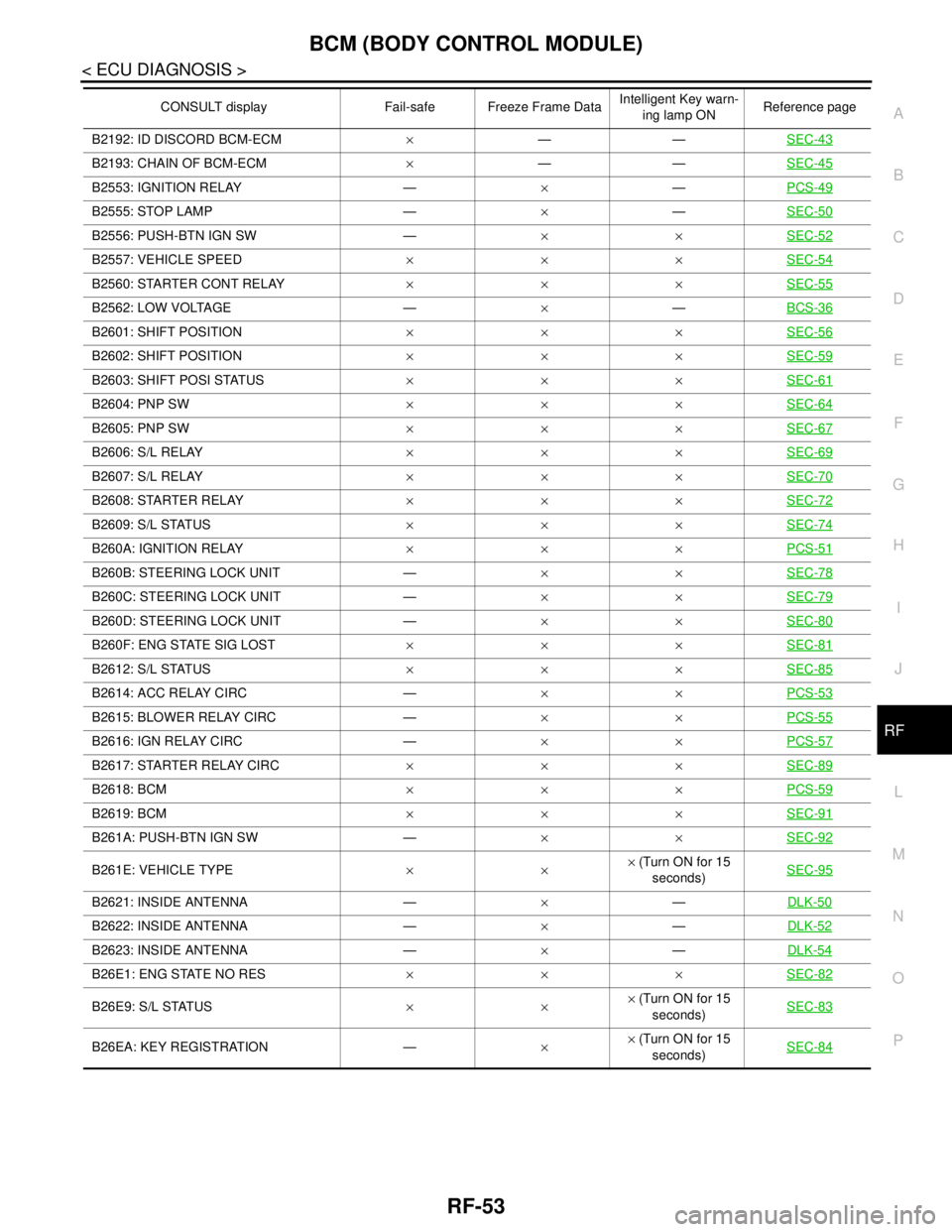
B2192: ID DISCORD BCM-ECM×——SEC-43
B2193: CHAIN OF BCM-ECM×——SEC-45
B2553: IGNITION RELAY —×—PCS-49
B2555: STOP LAMP —×—SEC-50
B2556: PUSH-BTN IGN SW —××SEC-52
B2557: VEHICLE SPEED×××SEC-54
B2560: STARTER CONT RELAY×××SEC-55
B2562: LOW VOLTAGE —×—BCS-36
B2601: SHIFT POSITION×××SEC-56
B2602: SHIFT POSITION×××SEC-59
B2603: SHIFT POSI STATUS×××SEC-61
B2604: PNP SW×××SEC-64
B2605: PNP SW×××SEC-67
B2606: S/L RELAY×××SEC-69
B2607: S/L RELAY×××SEC-70
B2608: STARTER RELAY×××SEC-72
B2609: S/L STATUS×××SEC-74
B260A: IGNITION RELAY×××PCS-51
B260B: STEERING LOCK UNIT —××SEC-78
B260C: STEERING LOCK UNIT —××SEC-79
B260D: STEERING LOCK UNIT —××SEC-80
B260F: ENG STATE SIG LOST×××SEC-81
B2612: S/L STATUS×××SEC-85
B2614: ACC RELAY CIRC —××PCS-53
B2615: BLOWER RELAY CIRC —××PCS-55
B2616: IGN RELAY CIRC —××PCS-57
B2617: STARTER RELAY CIRC×××SEC-89
B2618: BCM×××PCS-59
B2619: BCM×××SEC-91
B261A: PUSH-BTN IGN SW —××SEC-92
B261E: VEHICLE TYPE××× (Turn ON for 15
seconds)SEC-95
B2621: INSIDE ANTENNA —×—DLK-50
B2622: INSIDE ANTENNA —×—DLK-52
B2623: INSIDE ANTENNA —×—DLK-54
B26E1: ENG STATE NO RES×××SEC-82
B26E9: S/L STATUS××× (Turn ON for 15
seconds)SEC-83
B26EA: KEY REGISTRATION —×× (Turn ON for 15
seconds)SEC-84
CONSULT display Fail-safe Freeze Frame DataIntelligent Key warn-
ing lamp ONReference page
Page 3804 of 5121
SQUEAK AND RATTLE TROUBLE DIAGNOSES
RF-73
< SYMPTOM DIAGNOSIS >
C
D
E
F
G
H
I
J
L
MA
B
RF
N
O
P
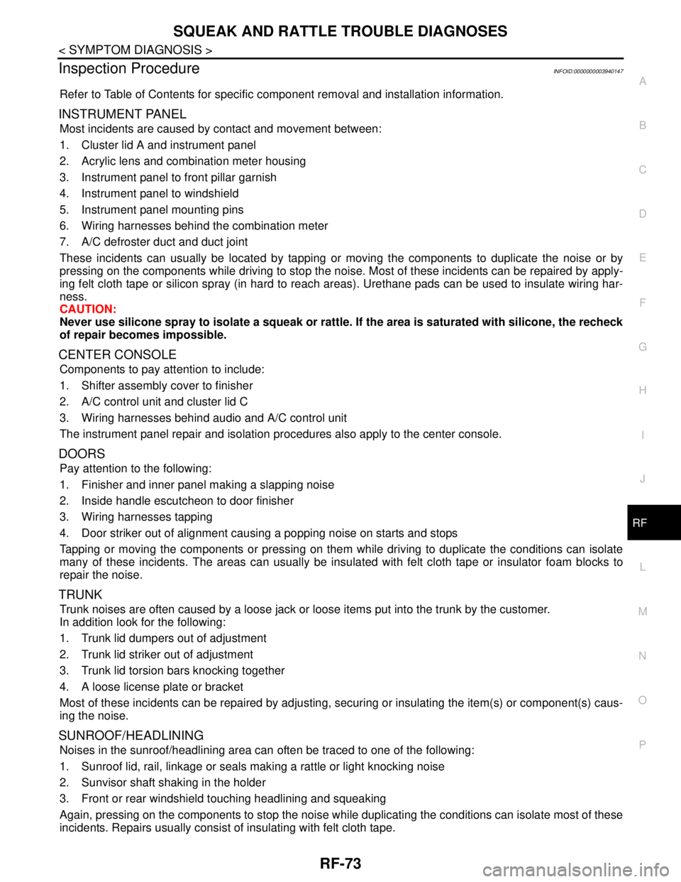
Inspection ProcedureINFOID:0000000003940147
Refer to Table of Contents for specific component removal and installation information.
INSTRUMENT PANEL
Most incidents are caused by contact and movement between:
1. Cluster lid A and instrument panel
2. Acrylic lens and combination meter housing
3. Instrument panel to front pillar garnish
4. Instrument panel to windshield
5. Instrument panel mounting pins
6. Wiring harnesses behind the combination meter
7. A/C defroster duct and duct joint
These incidents can usually be located by tapping or moving the components to duplicate the noise or by
pressing on the components while driving to stop the noise. Most of these incidents can be repaired by apply-
ing felt cloth tape or silicon spray (in hard to reach areas). Urethane pads can be used to insulate wiring har-
ness.
CAUTION:
Never use silicone spray to isolate a squeak or rattle. If the area is saturated with silicone, the recheck
of repair becomes impossible.
CENTER CONSOLE
Components to pay attention to include:
1. Shifter assembly cover to finisher
2. A/C control unit and cluster lid C
3. Wiring harnesses behind audio and A/C control unit
The instrument panel repair and isolation procedures also apply to the center console.
DOORS
Pay attention to the following:
1. Finisher and inner panel making a slapping noise
2. Inside handle escutcheon to door finisher
3. Wiring harnesses tapping
4. Door striker out of alignment causing a popping noise on starts and stops
Tapping or moving the components or pressing on them while driving to duplicate the conditions can isolate
many of these incidents. The areas can usually be insulated with felt cloth tape or insulator foam blocks to
repair the noise.
TRUNK
Trunk noises are often caused by a loose jack or loose items put into the trunk by the customer.
In addition look for the following:
1. Trunk lid dumpers out of adjustment
2. Trunk lid striker out of adjustment
3. Trunk lid torsion bars knocking together
4. A loose license plate or bracket
Most of these incidents can be repaired by adjusting, securing or insulating the item(s) or component(s) caus-
ing the noise.
SUNROOF/HEADLINING
Noises in the sunroof/headlining area can often be traced to one of the following:
1. Sunroof lid, rail, linkage or seals making a rattle or light knocking noise
2. Sunvisor shaft shaking in the holder
3. Front or rear windshield touching headlining and squeaking
Again, pressing on the components to stop the noise while duplicating the conditions can isolate most of these
incidents. Repairs usually consist of insulating with felt cloth tape.
Page 3946 of 5121

SE-82
< SYMPTOM DIAGNOSIS >[WITH VENTILATION SEAT]
SQUEAK AND RATTLE TROUBLE DIAGNOSES
Inspection Procedure
INFOID:0000000003940144
Refer to Table of Contents for specific component removal and installation information.
INSTRUMENT PANEL
Most incidents are caused by contact and movement between:
1. Cluster lid A and instrument panel
2. Acrylic lens and combination meter housing
3. Instrument panel to front pillar garnish
4. Instrument panel to windshield
5. Instrument panel mounting pins
6. Wiring harnesses behind the combination meter
7. A/C defroster duct and duct joint
These incidents can usually be located by tapping or moving the components to duplicate the noise or by
pressing on the components while driving to stop the noise. Most of these incidents can be repaired by apply-
ing felt cloth tape or silicon spray (in hard to reach areas). Urethane pads can be used to insulate wiring har-
ness.
CAUTION:
Never use silicone spray to isolate a squeak or rattle. If the area is saturated with silicone, the recheck
of repair becomes impossible.
CENTER CONSOLE
Components to pay attention to include:
1. Shifter assembly cover to finisher
2. A/C control unit and cluster lid C
3. Wiring harnesses behind audio and A/C control unit
The instrument panel repair and isolation procedures also apply to the center console.
DOORS
Pay attention to the following:
1. Finisher and inner panel making a slapping noise
2. Inside handle escutcheon to door finisher
3. Wiring harnesses tapping
4. Door striker out of alignment causing a popping noise on starts and stops
Tapping or moving the components or pressing on them while driving to duplicate the conditions can isolate
many of these incidents. The areas can usually be insulated with felt cloth tape or insulator foam blocks to
repair the noise.
TRUNK
Trunk noises are often caused by a loose jack or loose items put into the trunk by the customer.
In addition look for the following:
1. Trunk lid dumpers out of adjustment
2. Trunk lid striker out of adjustment
3. Trunk lid torsion bars knocking together
4. A loose license plate or bracket
Most of these incidents can be repaired by adjusting, securing or insulating the item(s) or component(s) caus-
ing the noise.
SUNROOF/HEADLINING
Noises in the sunroof/headlining area can often be traced to one of the following:
1. Sunroof lid, rail, linkage or seals making a rattle or light knocking noise
2. Sunvisor shaft shaking in the holder
3. Front or rear windshield touching headlining and squeaking
Again, pressing on the components to stop the noise while duplicating the conditions can isolate most of these
incidents. Repairs usually consist of insulating with felt cloth tape.
Page 3987 of 5121

SQUEAK AND RATTLE TROUBLE DIAGNOSES
SE-123
< SYMPTOM DIAGNOSIS >[WITHOUT VENTILATION SEAT]
C
D
E
F
G
H
I
K
L
MA
B
SE
N
O
P
Confirm that the cause of a noise is repaired by test driving the vehicle. Operate the vehicle under the same
conditions as when the noise originally occurred. Refer to the notes on the Diagnostic Worksheet.
Inspection ProcedureINFOID:0000000003940141
Refer to Table of Contents for specific component removal and installation information.
INSTRUMENT PANEL
Most incidents are caused by contact and movement between:
1. Cluster lid A and instrument panel
2. Acrylic lens and combination meter housing
3. Instrument panel to front pillar garnish
4. Instrument panel to windshield
5. Instrument panel mounting pins
6. Wiring harnesses behind the combination meter
7. A/C defroster duct and duct joint
These incidents can usually be located by tapping or moving the components to duplicate the noise or by
pressing on the components while driving to stop the noise. Most of these incidents can be repaired by apply-
ing felt cloth tape or silicon spray (in hard to reach areas). Urethane pads can be used to insulate wiring har-
ness.
CAUTION:
Never use silicone spray to isolate a squeak or rattle. If the area is saturated with silicone, the recheck
of repair becomes impossible.
CENTER CONSOLE
Components to pay attention to include:
1. Shifter assembly cover to finisher
2. A/C control unit and cluster lid C
3. Wiring harnesses behind audio and A/C control unit
The instrument panel repair and isolation procedures also apply to the center console.
DOORS
Pay attention to the following:
1. Finisher and inner panel making a slapping noise
2. Inside handle escutcheon to door finisher
3. Wiring harnesses tapping
4. Door striker out of alignment causing a popping noise on starts and stops
Tapping or moving the components or pressing on them while driving to duplicate the conditions can isolate
many of these incidents. The areas can usually be insulated with felt cloth tape or insulator foam blocks to
repair the noise.
TRUNK
Trunk noises are often caused by a loose jack or loose items put into the trunk by the customer.
In addition look for the following:
1. Trunk lid dumpers out of adjustment
2. Trunk lid striker out of adjustment
3. Trunk lid torsion bars knocking together
4. A loose license plate or bracket
Most of these incidents can be repaired by adjusting, securing or insulating the item(s) or component(s) caus-
ing the noise.
SUNROOF/HEADLINING
Noises in the sunroof/headlining area can often be traced to one of the following:
1. Sunroof lid, rail, linkage or seals making a rattle or light knocking noise
2. Sunvisor shaft shaking in the holder
3. Front or rear windshield touching headlining and squeaking
Page 4011 of 5121
SEC-2
Description ..............................................................34
DTC Logic ...............................................................34
Diagnosis Procedure ..............................................34
P1614 CHAIN OF IMMU-KEY ...........................35
Description ..............................................................35
DTC Logic ...............................................................35
Diagnosis Procedure ..............................................35
P1615 DIFFRENCE OF KEY .............................38
Description ..............................................................38
DTC Logic ...............................................................38
Diagnosis Procedure ..............................................38
B2190 NATS ANTENNA AMP. .........................39
Description ..............................................................39
DTC Logic ...............................................................39
Diagnosis Procedure ..............................................39
B2191 DIFFERENCE OF KEY ..........................42
Description ..............................................................42
DTC Logic ...............................................................42
Diagnosis Procedure ..............................................42
B2192 ID DISCORD, IMMU-ECM ......................43
Description ..............................................................43
DTC Logic ...............................................................43
Diagnosis Procedure ..............................................43
B2193 CHAIN OF ECM-IMMU ...........................45
Description ..............................................................45
DTC Logic ...............................................................45
Diagnosis Procedure ..............................................45
B2013 ID DISCORD, IMMU-STRG ....................46
Description ..............................................................46
DTC Logic ...............................................................46
Diagnosis Procedure ..............................................46
B2014 CHAIN OF STRG-IMMU .........................47
Description ..............................................................47
DTC Logic ...............................................................47
Diagnosis Procedure ..............................................47
B2555 STOP LAMP ...........................................50
Description ..............................................................50
DTC Logic ...............................................................50
Diagnosis Procedure ..............................................50
Component Inspection ............................................51
B2556 PUSH-BUTTON IGNITION SWITCH .....52
Description ..............................................................52
DTC Logic ...............................................................52
Diagnosis Procedure ..............................................52
Component Inspection ............................................53
B2557 VEHICLE SPEED ...................................54
Description ..............................................................54
DTC Logic ...............................................................54
Diagnosis Procedure ..............................................54
B2560 STARTER CONTROL RELAY ...............55
Description ..............................................................55
DTC Logic ...............................................................55
Diagnosis Procedure ...............................................55
B2601 SHIFT POSITION ...................................56
Description ..............................................................56
DTC Logic ...............................................................56
Diagnosis Procedure ...............................................56
Component Inspection ............................................58
B2602 SHIFT POSITION ...................................59
Description ..............................................................59
DTC Logic ...............................................................59
Diagnosis Procedure ...............................................59
B2603 SHIFT POSITION STATUS ....................61
Description ..............................................................61
DTC Logic ...............................................................61
VQ35DE MODELS ....................................................61
VQ35DE MODELS : Diagnosis Procedure .............61
VQ25DE MODELS ....................................................62
VQ25DE MODELS : Diagnosis Procedure .............62
B2604 PNP SWITCH .........................................64
Description ..............................................................64
DTC Logic ...............................................................64
VQ35DE MODELS ....................................................64
VQ35DE MODELS : Diagnosis Procedure .............64
VQ25DE MODELS ....................................................65
VQ25DE MODELS : Diagnosis Procedure .............65
B2605 PNP SWITCH .........................................67
Description ..............................................................67
DTC Logic ...............................................................67
Diagnosis Procedure ...............................................67
B2606 STEERING LOCK RELAY .....................69
Description ..............................................................69
DTC Logic ...............................................................69
Diagnosis Procedure ...............................................69
B2607 STEERING LOCK RELAY .....................70
Description ..............................................................70
DTC Logic ...............................................................70
Diagnosis Procedure ...............................................70
B2608 STARTER RELAY .................................72
Description ..............................................................72
DTC Logic ...............................................................72
Diagnosis Procedure ...............................................72
B2609 STEERING STATUS ..............................74
Description ..............................................................74
DTC Logic ...............................................................74
Diagnosis Procedure ...............................................74
B260B STEERING LOCK UNIT ........................78
Description ..............................................................78
DTC Logic ...............................................................78
Page 4018 of 5121

INTELLIGENT KEY SYSTEM/ENGINE START FUNCTION
SEC-9
< FUNCTION DIAGNOSIS >[INTELLIGENT KEY SYSTEM]
C
D
E
F
G
H
I
J
L
MA
B
SEC
N
O
P
FUNCTION DIAGNOSIS
INTELLIGENT KEY SYSTEM/ENGINE START FUNCTION
System DiagramINFOID:0000000003814902
System DescriptionINFOID:0000000003814903
The engine start function of Intelligent Key system is a system that makes it possible to start and stop the
engine without removing the key. It verifies the electronic ID using two-way communication when pressing
the push-button ignition switch while carrying the Intelligent Key, which operates based on the results of
electronic ID verification for Intelligent Key using two-way communication between the Intelligent Key and
the vehicle.
NOTE:
The driver should carry the Intelligent Key at all times.
Intelligent Key has 2 IDs [for Intelligent Key and for NVIS (NATS)]. It can perform the door lock/unlock oper-
ation and the push-button ignition switch operation when the registered Intelligent Key is carried.
When the Intelligent Key battery is discharged, it can be used as emergency back-up by inserting the Intelli-
gent Key to the key slot. At that time, perform the NVIS (NATS) ID verification. If it is used when the Intelli-
gent Key is carried, perform the Intelligent Key ID verification.
If the ID is successfully verified, and when push-button ignition switch is pressed, steering lock will be
released and starting the engine will be possible.
If the door lock/unlock operation is performed when the Intelligent Key battery is discharged, all doors lock/
unlock can be performed by operating the driver door key cylinder using the mechanical key set in the Intel-
ligent Key.
Up to 4 Intelligent Keys can be registered (Including the standard Intelligent Key) on request from the owner.
NOTE:
Refer to SEC-9, "
System Description" for any functions other than engine start function of Intelligent Key
system.
PRECAUTIONS FOR INTELLIGENT KEY SYSTEM
In the Intelligent Key system, the transponder [the chip for NVIS (NATS) ID verification] is integrated
into the Intelligent Key. (For the conventional models, it is integrated into the mechanical key.) There-
fore, the mechanical key cannot perform the ID verification, and thus it cannot start the engine.
Instead, the NVIS (NATS) ID verification can be performed by inserting the Intelligent Key into the key
slot, and then it can start the engine.
OPERATION WHEN INTELLIGENT KEY IS CARRIED
1. When the push-button ignition switch is pressed, the BCM signals the inside key antenna and transmits
the request signal to the Intelligent Key.
2. The Intelligent Key receives the request signal and transmits the Intelligent Key ID signal to the BCM via
the remote keyless entry receiver.
3. The BCM receives the Intelligent Key ID signal and verifies it with the registered ID.
JMKIA1870GB
Page 4019 of 5121

SEC-10
< FUNCTION DIAGNOSIS >[INTELLIGENT KEY SYSTEM]
INTELLIGENT KEY SYSTEM/ENGINE START FUNCTION
4. BCM transmits the steering lock unlock signal to steering lock unit and IPDM E/R if the verification results
are OK.
5. IPDM E/R turns the steering lock relay ON and supplies power to the steering lock unit.
6. Release of the steering lock.
7. BCM transmits the power supply stop signal to IPDM E/R when it confirms that the steering lock is in the
unlock condition.
8. IPDM E/R turns the steering lock relay OFF and stops power supply to the steering lock unit.
9. BCM turns ACC relay ON and transmits the ignition power supply ON signal to IPDM E/R.
10. IPDM E/R turns the ignition relay ON and starts the ignition power supply.
11. BCM confirms that the shift position is P or N.
12. BCM transmits the starter request signal via CAN communication to IPDM E/R and turns the starter relay
in IPDM E/R ON if BCM judges that the engine start condition is satisfied.
13. IPDM E/R turns the starter control relay ON when receiving the starter request signal.
14. Battery power is supplied through the starter relay and the starter control relay to operate the starter motor
and to start the cranking.
CAUTION:
If a malfunction is detected in the Intelligent Key system, the “KEY” warning lamp in the combina-
tion meter illuminates. At that time, the engine cannot be started.
15. When BCM receives feedback signal from ECM acknowledging the engine has been initiated, the BCM
transmits a stop signal to IPDM E/R and stops the cranking by turning OFF the starter motor relay. (If the
engine initiating has failed, the cranking will stop automatically within 5 seconds.)
CAUTION:
When the Intelligent Key is carried outside of the vehicle (inside key antenna detection area) with
the power supply in the ACC or ON position, even if the engine start condition* is satisfied, the
engine cannot be started.
*: For the engine start condition, refer to “PUSH-BUTTON IGNITION SWITCH OPERATION PROCEDURE”.
OPERATION RANGE
Engine can be started when Intelligent Key is inside the vehicle. However, sometimes engine might not start
when Intelligent Key is on instrument panel or in glove box.
OPERATION WHEN KEY SLOT IS USED
When the Intelligent Key battery is discharged, it performs the NVIS (NATS) ID verification between the inte-
grated transponder and BCM by inserting the Intelligent Key into the key slot, and then the engine can be
started.
For details relating to starting the engine using key slot, refer to SEC-14, "
System Description".
BATTERY SAVER SYSTEM
When all the following conditions are met for 60 minutes, the battery saver system will cut off the power supply
to prevent battery discharge.
The ignition switch is in the ACC position
All doors are closed
Selector lever is in the P position
Reset Condition of Battery Saver System
If any of the following conditions are met the battery saver system is released and the steering will change
automatically to the lock position from the OFF position.
Opening any door
Operating with request switch on door lock
Operating with Intelligent Key on door lock
Pressing the push-button ignition switch and ignition switch will change the ignition switch to ACC position
from OFF position.
STEERING LOCK OPERATION
Steering is locked by steering lock unit when ignition switch is in the OFF position, selector lever is in the P
position and any of the following conditions are met.
Opening door
Closing door
Door is locked with request switch
Door is locked with Intelligent Key