width NISSAN TEANA 2008 User Guide
[x] Cancel search | Manufacturer: NISSAN, Model Year: 2008, Model line: TEANA, Model: NISSAN TEANA 2008Pages: 5121, PDF Size: 69.03 MB
Page 1607 of 5121
![NISSAN TEANA 2008 User Guide EC-146
< COMPONENT DIAGNOSIS >[VQ25DE, VQ35DE]
P0075, P0081 IVT CONTROL SOLENOID VALVE
P0075, P0081 IVT CONTROL SOLENOID VALVE
DescriptionINFOID:0000000003856523
Intake valve timing control solenoid v NISSAN TEANA 2008 User Guide EC-146
< COMPONENT DIAGNOSIS >[VQ25DE, VQ35DE]
P0075, P0081 IVT CONTROL SOLENOID VALVE
P0075, P0081 IVT CONTROL SOLENOID VALVE
DescriptionINFOID:0000000003856523
Intake valve timing control solenoid v](/img/5/57391/w960_57391-1606.png)
EC-146
< COMPONENT DIAGNOSIS >[VQ25DE, VQ35DE]
P0075, P0081 IVT CONTROL SOLENOID VALVE
P0075, P0081 IVT CONTROL SOLENOID VALVE
DescriptionINFOID:0000000003856523
Intake valve timing control solenoid valve is activated by ON/OFF
pulse duty (ratio) signals from the ECM.
The intake valve timing control solenoid valve changes the oil
amount and direction of flow through intake valve timing control unit
or stops oil flow.
The longer pulse width advances valve angle.
The shorter pulse width retards valve angle.
When ON and OFF pulse widths become equal, the solenoid valve
stops oil pressure flow to fix the intake valve angle at the control
position.
DTC LogicINFOID:0000000003856524
DTC DETECTION LOGIC
DTC CONFIRMATION PROCEDURE
1.PRECONDITIONING
If DTC Confirmation Procedure has been previously conducted, always turn ignition switch OFF and wait at
least 10 seconds before conducting the next test.
>> GO TO 2.
2.PERFORM DTC CONFIRMATION PROCEDURE
1. Start engine and let it idle for 5 seconds.
2. Check 1st trip DTC.
Is 1st trip DTC detected?
YES >> Go to EC-146, "Diagnosis Procedure".
NO >> INSPECTION END
Diagnosis ProcedureINFOID:0000000003856525
1.CHECK INTAKE VALVE TIMING CONTROL SOLENOID VALVE POWER SUPPLY CIRCUIT
1. Turn ignition switch OFF.
2. Disconnect intake valve timing control solenoid valve harness connector.
3. Turn ignition switch ON.
4. Check the voltage between intake valve timing (IVT) control solenoid valve harness connector and ground
with CONSULT-III or tester.
Is the inspection result normal?
YES >> GO TO 2.
PBIB1842E
DTC No. Trouble diagnosis name DTC detecting condition Possible cause
P0075Intake valve timing control so-
lenoid valve (bank 1) circuitAn improper voltage is sent to the ECM
through intake valve timing control solenoid
valve. Harness or connectors
(Intake valve timing control solenoid valve
circuit is open or shorted.)
Intake valve timing control solenoid valve P0081Intake valve timing control so-
lenoid valve (bank 2) circuit
DTCIVT control solenoid valve
Ground Voltage
Bank Connector Terminal
P0075 1 F81 2
Ground Battery voltage
P0081 2 F82 2
Page 1884 of 5121
PREPARATION
EM-9
< PREPARATION >
C
D
E
F
G
H
I
J
K
L
MA
EM
N
P O
Commercial Service ToolINFOID:0000000003802235
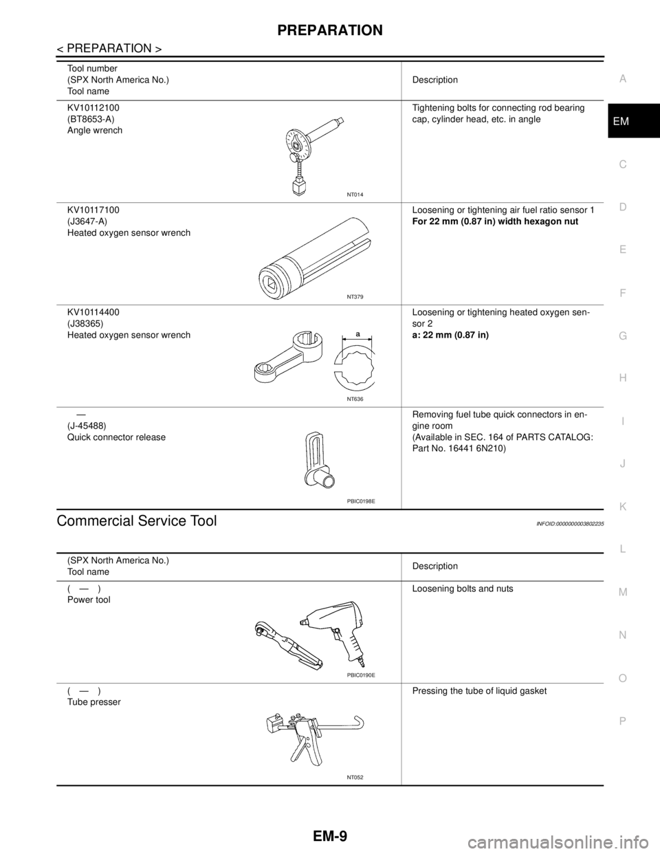
KV10112100
(BT8653-A)
Angle wrenchTightening bolts for connecting rod bearing
cap, cylinder head, etc. in angle
KV10117100
(J3647-A)
Heated oxygen sensor wrenchLoosening or tightening air fuel ratio sensor 1
For 22 mm (0.87 in) width hexagon nut
KV10114400
(J38365)
Heated oxygen sensor wrenchLoosening or tightening heated oxygen sen-
sor 2
a: 22 mm (0.87 in)
—
(J-45488)
Quick connector releaseRemoving fuel tube quick connectors in en-
gine room
(Available in SEC. 164 of PARTS CATALOG:
Part No. 16441 6N210) Tool number
(SPX North America No.)
Tool nameDescription
NT014
NT379
NT636
PBIC0198E
(SPX North America No.)
Tool nameDescription
(—)
Power toolLoosening bolts and nuts
(—)
Tube presserPressing the tube of liquid gasket
PBIC0190E
NT052
Page 2001 of 5121
EM-126
< DISASSEMBLY AND ASSEMBLY >
CYLINDER BLOCK
If the calculated value exceeds the limit, select proper connecting rod bearing according to connecting rod
big end diameter and crankshaft pin journal diameter to obtain the specified bearing oil clearance. Refer to
EM-130, "
ConnectingRodBearing".
Method of Using Plastigage
Remove oil and dust on crankshaft pin journal and the surfaces of each bearing completely.
Cut a plastigage slightly shorter than the bearing width, and place it in crankshaft axial direction, avoiding oil
holes.
Install connecting rod bearings to connecting rod and connecting rod bearing cap, and tighten connecting
rod bolts to the specified torque. Refer to EM-110, "
Disassembly and Assembly" for the tightening proce-
dure.
CAUTION:
Never rotate crankshaft.
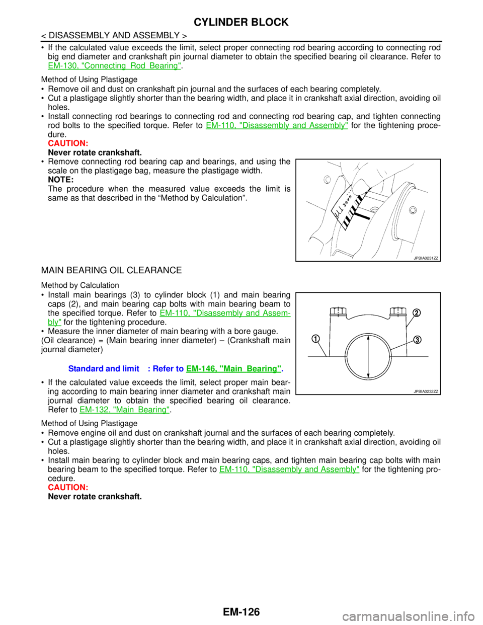
Remove connecting rod bearing cap and bearings, and using the
scale on the plastigage bag, measure the plastigage width.
NOTE:
The procedure when the measured value exceeds the limit is
same as that described in the “Method by Calculation”.
MAIN BEARING OIL CLEARANCE
Method by Calculation
Install main bearings (3) to cylinder block (1) and main bearing
caps (2), and main bearing cap bolts with main bearing beam to
the specified torque. Refer to EM-110, "
Disassembly and Assem-
bly" for the tightening procedure.
Measure the inner diameter of main bearing with a bore gauge.
(Oil clearance) = (Main bearing inner diameter) – (Crankshaft main
journal diameter)
If the calculated value exceeds the limit, select proper main bear-
ing according to main bearing inner diameter and crankshaft main
journal diameter to obtain the specified bearing oil clearance.
Refer to EM-132, "
MainBearing".
Method of Using Plastigage
Remove engine oil and dust on crankshaft journal and the surfaces of each bearing completely.
Cut a plastigage slightly shorter than the bearing width, and place it in crankshaft axial direction, avoiding oil
holes.
Install main bearing to cylinder block and main bearing caps, and tighten main bearing cap bolts with main
bearing beam to the specified torque. Refer to EM-110, "
Disassembly and Assembly" for the tightening pro-
cedure.
CAUTION:
Never rotate crankshaft.
JPBIA0231ZZ
Standard and limit : Refer to EM-146, "MainBearing".
JPBIA0232ZZ
Page 2002 of 5121
CYLINDER BLOCK
EM-127
< DISASSEMBLY AND ASSEMBLY >
C
D
E
F
G
H
I
J
K
L
MA
EM
N
P O
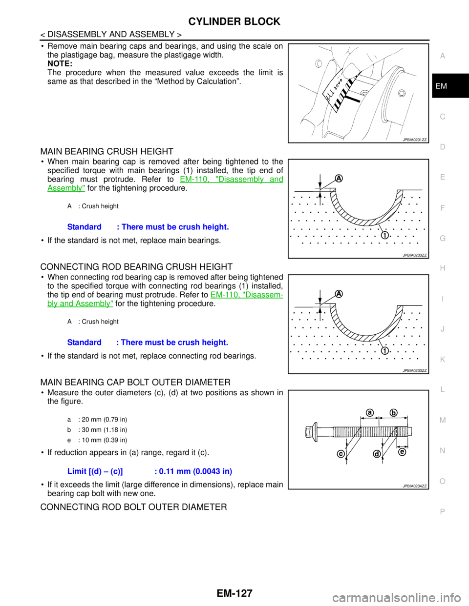
Remove main bearing caps and bearings, and using the scale on
the plastigage bag, measure the plastigage width.
NOTE:
The procedure when the measured value exceeds the limit is
same as that described in the “Method by Calculation”.
MAIN BEARING CRUSH HEIGHT
When main bearing cap is removed after being tightened to the
specified torque with main bearings (1) installed, the tip end of
bearing must protrude. Refer to EM-110, "
Disassembly and
Assembly" for the tightening procedure.
If the standard is not met, replace main bearings.
CONNECTING ROD BEARING CRUSH HEIGHT
When connecting rod bearing cap is removed after being tightened
to the specified torque with connecting rod bearings (1) installed,
the tip end of bearing must protrude. Refer to EM-110, "
Disassem-
bly and Assembly" for the tightening procedure.
If the standard is not met, replace connecting rod bearings.
MAIN BEARING CAP BOLT OUTER DIAMETER
Measure the outer diameters (c), (d) at two positions as shown in
the figure.
If reduction appears in (a) range, regard it (c).
If it exceeds the limit (large difference in dimensions), replace main
bearing cap bolt with new one.
CONNECTING ROD BOLT OUTER DIAMETER
JPBIA0231ZZ
A : Crush height
Standard : There must be crush height.
JPBIA0233ZZ
A : Crush height
Standard : There must be crush height.
JPBIA0233ZZ
a : 20 mm (0.79 in)
b : 30 mm (1.18 in)
e : 10 mm (0.39 in)
Limit [(d) – (c)] : 0.11 mm (0.0043 in)
JPBIA0234ZZ
Page 2016 of 5121
SERVICE DATA AND SPECIFICATIONS (SDS)
EM-141
< SERVICE DATA AND SPECIFICATIONS (SDS)
C
D
E
F
G
H
I
J
K
L
MA
EM
N
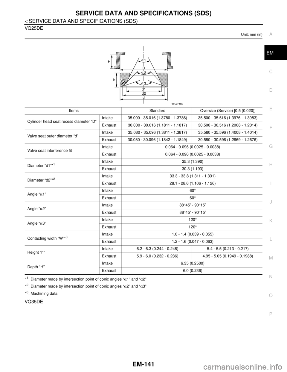
P O VQ25DE
Unit: mm (in)
*1: Diameter made by intersection point of conic angles “α1” and “α2”
*
2: Diameter made by intersection point of conic angles “α2” and “α3”
*
3: Machining data
VQ35DE
Items Standard Oversize (Service) [0.5 (0.020)]
Cylinder head seat recess diameter “D”Intake 35.000 - 35.016 (1.3780 - 1.3786) 35.500 - 35.516 (1.3976 - 1.3983)
Exhaust 30.000 - 30.016 (1.1811 - 1.1817) 30.500 - 30.516 (1.2008 - 1.2014)
Valve seat outer diameter “d”Intake 35.080 - 35.096 (1.3811 - 1.3817) 35.580 - 35.596 (1.4008 - 1.4014)
Exhaust 30.080 - 30.096 (1.1842 - 1.1849) 30.580 - 30.596 (1.2669 - 1.2676)
Valve seat interference fitIntake 0.064 - 0.096 (0.0025 - 0.0038)
Exhaust 0.064 - 0.096 (0.0025 - 0.0038)
Diameter “d1”*
1Intake 35.3 (1.390)
Exhaust 30.3 (1.193)
Diameter “d2”*
2Intake 33.3 - 33.8 (1.311 - 1.331)
Exhaust 28.1 - 28.6 (1.106 - 1.126)
Angle “α1”Intake 60°
Exhaust 60°
Angle “α2”Intake 88°45′ - 90°15′
Exhaust 88°45′ - 90°15′
Angle “α3”Intake 120°
Exhaust 120°
Contacting width “W”*
3Intake 1.0 - 1.4 (0.039 - 0.055)
Exhaust 1.2 - 1.6 (0.047 - 0.063)
Height “h”Intake 6.2 - 6.3 (0.244 - 0.248) 5.4 - 5.5 (0.213 - 0.217)
Exhaust 5.9 - 6.0 (0.232 - 0.236) 4.95 - 5.05 (0.1949 - 0.1988)
Depth “H”Intake 6.35 (0.2500)
Exhaust 6.0 (0.236)
PBIC2745E
Page 2017 of 5121
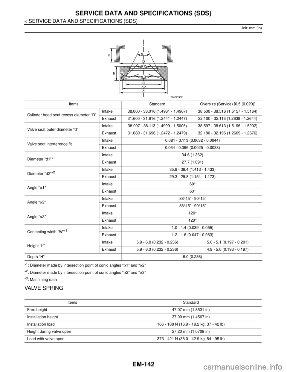
EM-142
< SERVICE DATA AND SPECIFICATIONS (SDS)
SERVICE DATA AND SPECIFICATIONS (SDS)
Unit: mm (in)
*1: Diameter made by intersection point of conic angles “α1” and “α2”
*
2: Diameter made by intersection point of conic angles “α2” and “α3”
*
3: Machining data
VALVE SPRING
Items Standard Oversize (Service) [0.5 (0.020)]
Cylinder head seat recess diameter “D”Intake 38.000 - 38.016 (1.4961 - 1.4967) 38.500 - 38.516 (1.5157 - 1.5164)
Exhaust 31.600 - 31.616 (1.2441 - 1.2447) 32.100 - 32.116 (1.2638 - 1.2644)
Valve seat outer diameter “d”Intake 38.097 - 38.113 (1.4999 - 1.5005) 38.597 - 38.613 (1.5196 - 1.5202)
Exhaust 31.680 - 31.696 (1.2472 - 1.2479) 32.180 - 32.196 (1.2669 - 1.2676)
Valve seat interference fitIntake 0.081 - 0.113 (0.0032 - 0.0044)
Exhaust 0.064 - 0.096 (0.0025 - 0.0038)
Diameter “d1”*
1Intake 34.6 (1.362)
Exhaust 27.7 (1.091)
Diameter “d2”*
2Intake 35.9 - 36.4 (1.413 - 1.433)
Exhaust 29.3 - 29.8 (1.154 - 1.173)
Angle “α1”Intake 60°
Exhaust 60°
Angle “α2”Intake 88°45′ - 90°15′
Exhaust 88°45′ - 90°15′
Angle “α3”Intake 120°
Exhaust 120°
Contacting width “W”*
3Intake 1.0 - 1.4 (0.039 - 0.055)
Exhaust 1.2 - 1.6 (0.047 - 0.063)
Height “h”Intake 5.9 - 6.0 (0.232 - 0.236) 5.0 - 5.1 (0.197 - 0.201)
Exhaust 5.9 - 6.0 (0.232 - 0.236) 4.9 - 5.0 (0.193 - 0.197)
Depth “H”6.0 (0.236)
PBIC2745E
Items Standard
Free height 47.07 mm (1.8531 in)
Installation height 37.00 mm (1.4567 in)
Installation load 166 - 188 N (16.9 - 19.2 kg, 37 - 42 lb)
Height during valve open 27.20 mm (1.0709 in)
Load with valve open 373 - 421 N (38.0 - 42.9 kg, 84 - 95 lb)
Page 2022 of 5121
SERVICE DATA AND SPECIFICATIONS (SDS)
EM-147
< SERVICE DATA AND SPECIFICATIONS (SDS)
C
D
E
F
G
H
I
J
K
L
MA
EM
N
P O
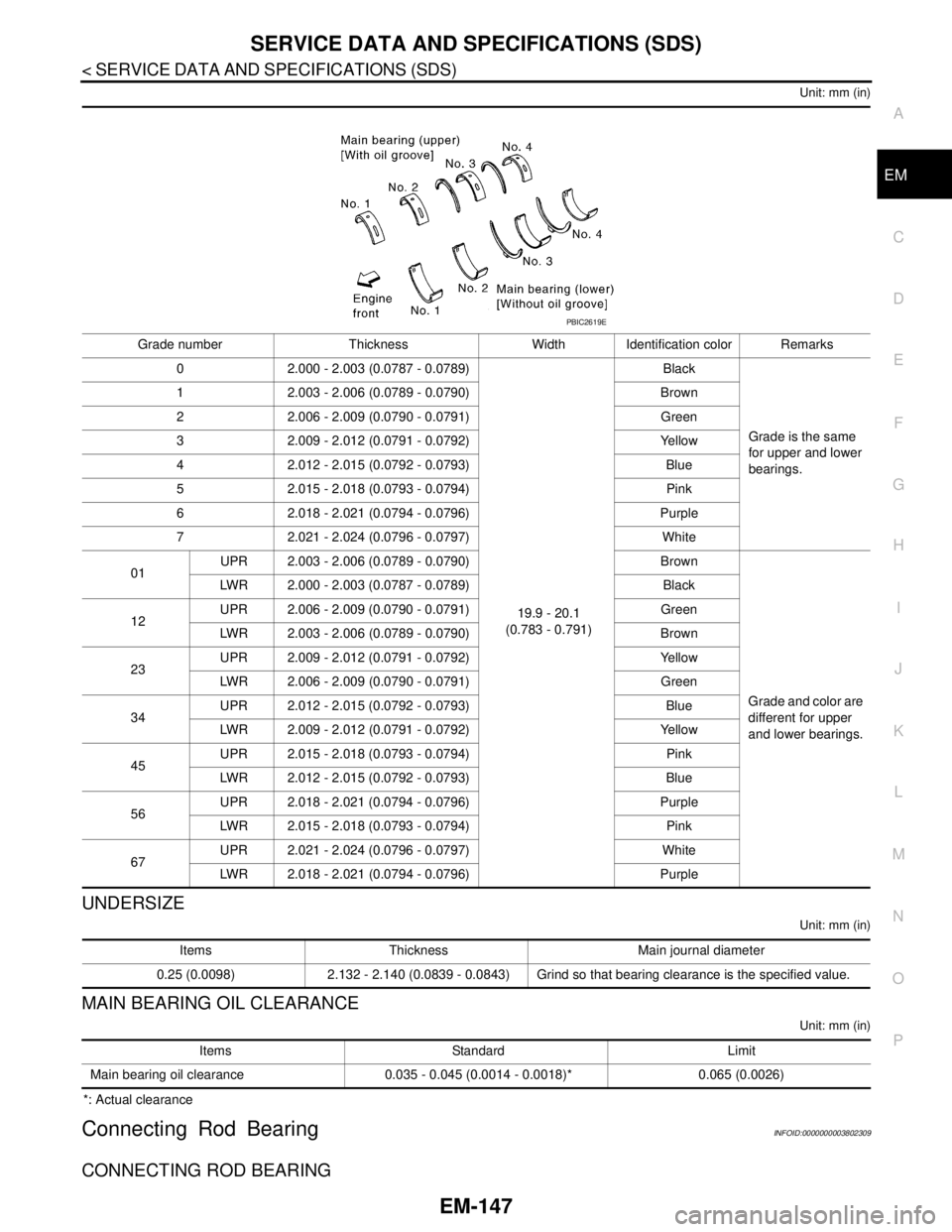
Unit: mm (in)
UNDERSIZE
Unit: mm (in)
MAIN BEARING OIL CLEARANCE
Unit: mm (in)
*: Actual clearance
Connecting Rod BearingINFOID:0000000003802309
CONNECTING ROD BEARING
Grade number Thickness Width Identification color Remarks
0 2.000 - 2.003 (0.0787 - 0.0789)
19.9 - 20.1
(0.783 - 0.791)Black
Grade is the same
for upper and lower
bearings. 1 2.003 - 2.006 (0.0789 - 0.0790) Brown
2 2.006 - 2.009 (0.0790 - 0.0791) Green
3 2.009 - 2.012 (0.0791 - 0.0792) Yellow
4 2.012 - 2.015 (0.0792 - 0.0793) Blue
5 2.015 - 2.018 (0.0793 - 0.0794) Pink
6 2.018 - 2.021 (0.0794 - 0.0796) Purple
7 2.021 - 2.024 (0.0796 - 0.0797) White
01UPR 2.003 - 2.006 (0.0789 - 0.0790) Brown
Grade and color are
different for upper
and lower bearings. LWR 2.000 - 2.003 (0.0787 - 0.0789) Black
12UPR 2.006 - 2.009 (0.0790 - 0.0791) Green
LWR 2.003 - 2.006 (0.0789 - 0.0790) Brown
23UPR 2.009 - 2.012 (0.0791 - 0.0792) Yellow
LWR 2.006 - 2.009 (0.0790 - 0.0791) Green
34UPR 2.012 - 2.015 (0.0792 - 0.0793) Blue
LWR 2.009 - 2.012 (0.0791 - 0.0792) Yellow
45UPR 2.015 - 2.018 (0.0793 - 0.0794) Pink
LWR 2.012 - 2.015 (0.0792 - 0.0793) Blue
56UPR 2.018 - 2.021 (0.0794 - 0.0796) Purple
LWR 2.015 - 2.018 (0.0793 - 0.0794) Pink
67UPR 2.021 - 2.024 (0.0796 - 0.0797) White
LWR 2.018 - 2.021 (0.0794 - 0.0796) Purple
PBIC2619E
Items Thickness Main journal diameter
0.25 (0.0098) 2.132 - 2.140 (0.0839 - 0.0843) Grind so that bearing clearance is the specified value.
Items Standard Limit
Main bearing oil clearance 0.035 - 0.045 (0.0014 - 0.0018)* 0.065 (0.0026)
Page 2472 of 5121
FUEL TANK
FL-9
< ON-VEHICLE REPAIR >
C
D
E
F
G
H
I
J
K
L
MA
FL
N
P O
FUEL TANK
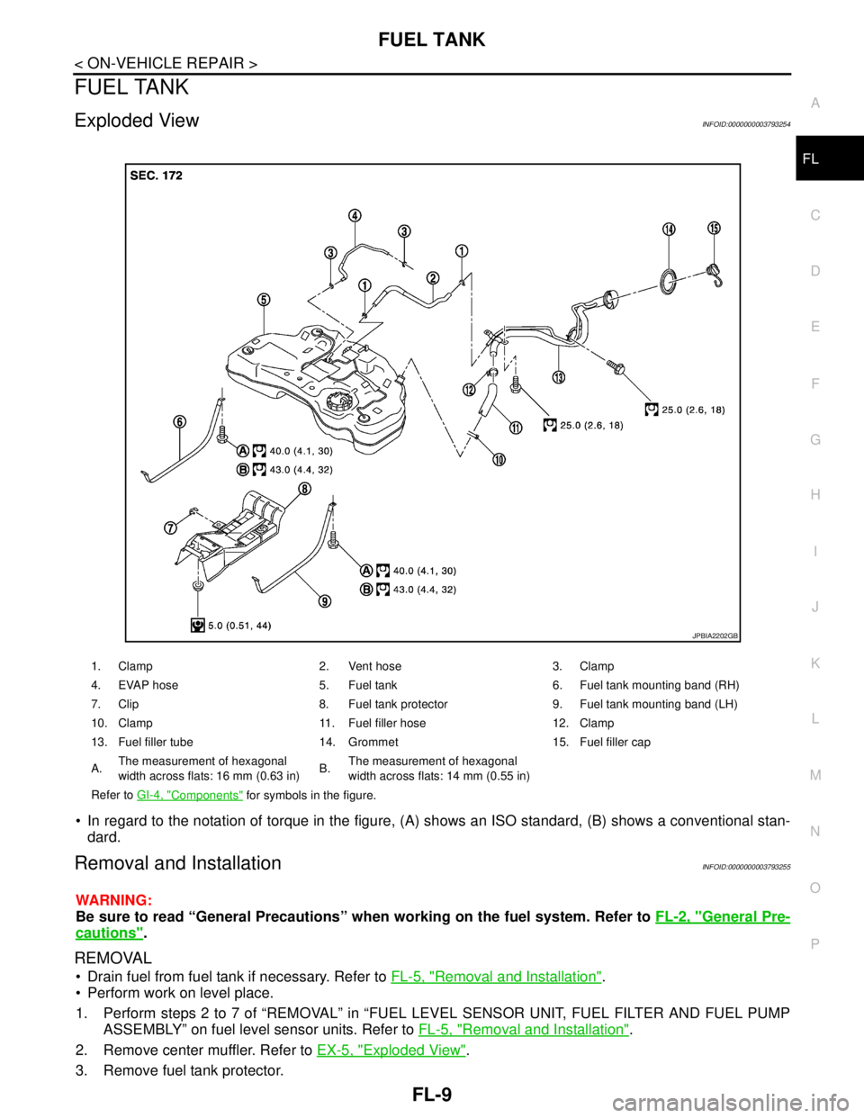
Exploded ViewINFOID:0000000003793254
In regard to the notation of torque in the figure, (A) shows an ISO standard, (B) shows a conventional stan-
dard.
Removal and InstallationINFOID:0000000003793255
WARNING:
Be sure to read “General Precautions” when working on the fuel system. Refer to FL-2, "
General Pre-
cautions".
REMOVAL
Drain fuel from fuel tank if necessary. Refer to FL-5, "Removal and Installation".
Perform work on level place.
1. Perform steps 2 to 7 of “REMOVAL” in “FUEL LEVEL SENSOR UNIT, FUEL FILTER AND FUEL PUMP
ASSEMBLY” on fuel level sensor units. Refer to FL-5, "
Removal and Installation".
2. Remove center muffler. Refer to EX-5, "
Exploded View".
3. Remove fuel tank protector.
1. Clamp 2. Vent hose 3. Clamp
4. EVAP hose 5. Fuel tank 6. Fuel tank mounting band (RH)
7. Clip 8. Fuel tank protector 9. Fuel tank mounting band (LH)
10. Clamp 11. Fuel filler hose 12. Clamp
13. Fuel filler tube 14. Grommet 15. Fuel filler cap
A.The measurement of hexagonal
width across flats: 16 mm (0.63 in)B.The measurement of hexagonal
width across flats: 14 mm (0.55 in)
Refer to GI-4, "
Components" for symbols in the figure.
JPBIA2202GB
Page 2507 of 5121
GI-14
< HOW TO USE THIS MANUAL >
TIGHTENING TORQUE OF STANDARD BOLTS
TIGHTENING TORQUE OF STANDARD BOLTS
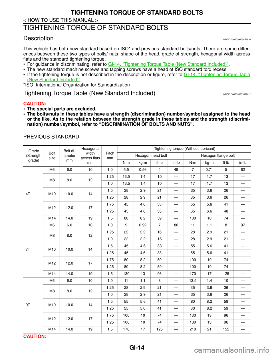
DescriptionINFOID:0000000003852910
This vehicle has both new standard based on ISO* and previous standard bolts/nuts. There are some differ-
ences between these two types of bolts/ nuts; shape of the head, grade of strength, hexagonal width across
flats and the standard tightening torque.
For guidance in discriminating, refer to GI-14, "
Tightening Torque Table (New Standard Included)".
The new standard machine screws and tapping screws have a head of ISO standard torx recess.
If the tightening torque is not described in the description or figure, refer to GI-14, "
Tightening Torque Table
(New Standard Included)".
*ISO: International Organization for Standardization
Tightening Torque Table (New Standard Included)INFOID:0000000003852911
CAUTION:
The special parts are excluded.
The bolts/nuts in these tables have a strength (discrimination) number/symbol assigned to the head
or the like. As to the relation between the strength grade in these tables and the strength (discrimi-
nation) number/symbol, refer to “DISCRIMINATION OF BOLTS AND NUTS”.
PREVIOUS STANDARD
CAUTION:
Grade
(Strength
grade)Bolt
sizeBolt di-
ameter
mmHexagonal
width
across flats
mmPitch
mmTightening torque (Without lubricant)
Hexagon head bolt Hexagon flange bolt
N·m kg-m ft-lb in-lb N·m kg-m ft-lb in-lb
4TM6 6.0 10 1.0 5.5 0.56 4 49 7 0.71 5 62
M8 8.0 121.25 13.5 1.4 10 — 17 1.7 13 —
1.0 13.5 1.4 10 — 17 1.7 13 —
M10 10.0 141.5 28 2.9 21 — 35 3.6 26 —
1.25 28 2.9 21 — 35 3.6 26 —
M12 12.0 171.75 45 4.6 33 — 55 5.6 41 —
1.25 45 4.6 33 — 65 6.6 48 —
M14 14.0 19 1.5 80 8.2 59 — 100 10 74 —
7TM6 6.0 10 1.0 9 0.92 7 80 11 1.1 8 97
M8 8.0 121.25 22 2.2 16 — 28 2.9 21 —
1.0 22 2.2 16 — 28 2.9 21 —
M10 10.0 141.5 45 4.6 33 — 55 5.6 41 —
1.25 45 4.6 33 — 55 5.6 41 —
M12 12.0 171.75 80 8.2 59 — 100 10 74 —
1.25 80 8.2 59 — 100 10 74 —
M14 14.0 19 1.5 130 13 96 — 170 17 125 —
9TM6 6.0 10 1.0 11 1.1 8 — 13.5 1.4 10 —
M8 8.0 121.25 28 2.9 21 — 35 3.6 26 —
1.0 28 2.9 21 — 35 3.6 26 —
M10 10.0 141.5 55 5.6 41 — 80 8.2 59 —
1.25 55 5.6 41 — 80 8.2 59 —
M12 12.0 171.75 100 10 74 — 130 13 96 —
1.25 100 10 74 — 130 13 96 —
M14 14.0 19 1.5 170 17 125 — 210 21 155 —
Page 2508 of 5121
TIGHTENING TORQUE OF STANDARD BOLTS
GI-15
< HOW TO USE THIS MANUAL >
C
D
E
F
G
H
I
J
K
L
MB
GI
N
O
P
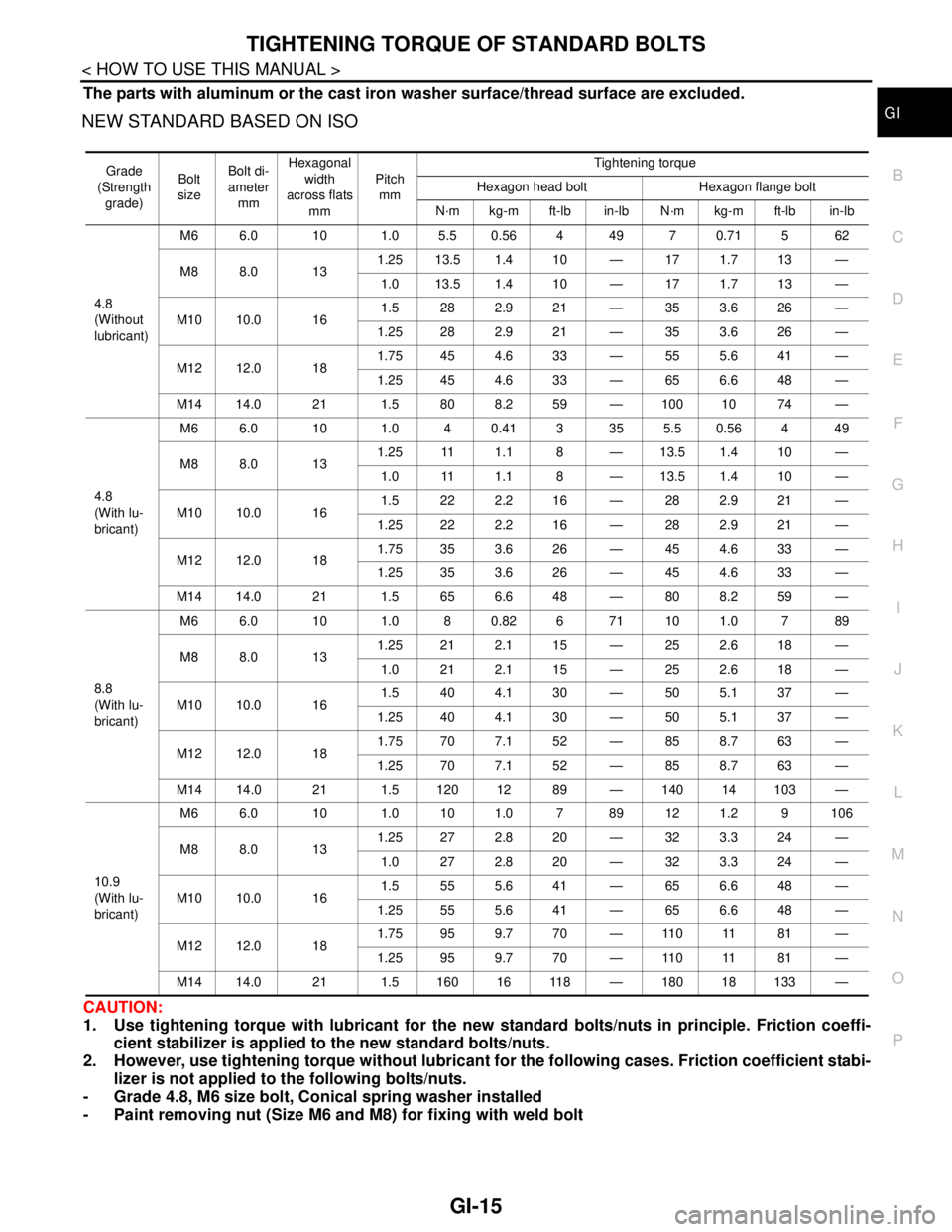
The parts with aluminum or the cast iron washer surface/thread surface are excluded.
NEW STANDARD BASED ON ISO
CAUTION:
1. Use tightening torque with lubricant for the new standard bolts/nuts in principle. Friction coeffi-
cient stabilizer is applied to the new standard bolts/nuts.
2. However, use tightening torque without lubricant for the following cases. Friction coefficient stabi-
lizer is not applied to the following bolts/nuts.
- Grade 4.8, M6 size bolt, Conical spring washer installed
- Paint removing nut (Size M6 and M8) for fixing with weld bolt
Grade
(Strength
grade)Bolt
sizeBolt di-
ameter
mmHexagonal
width
across flats
mmPitch
mmTightening torque
Hexagon head bolt Hexagon flange bolt
N·m kg-m ft-lb in-lb N·m kg-m ft-lb in-lb
4.8
(Without
lubricant)M6 6.0 10 1.0 5.5 0.56 4 49 7 0.71 5 62
M8 8.0 131.25 13.5 1.4 10 — 17 1.7 13 —
1.0 13.5 1.4 10 — 17 1.7 13 —
M10 10.0 161.5 282.921 — 353.626 —
1.25 28 2.9 21 — 35 3.6 26 —
M12 12.0 181.75 45 4.6 33 — 55 5.6 41 —
1.25 45 4.6 33 — 65 6.6 48 —
M14 14.0 21 1.5 80 8.2 59 — 100 10 74 —
4.8
(With lu-
bricant)M6 6.0 10 1.0 40.413 355.50.564 49
M8 8.0 131.25 11 1.1 8 — 13.5 1.4 10 —
1.0 11 1.1 8 — 13.5 1.4 10 —
M10 10.0 161.5 222.216 — 282.921 —
1.25 22 2.2 16 — 28 2.9 21 —
M12 12.0 181.75 35 3.6 26 — 45 4.6 33 —
1.25 35 3.6 26 — 45 4.6 33 —
M14 14.0 21 1.5 65 6.6 48 — 80 8.2 59 —
8.8
(With lu-
bricant)M6 6.0 10 1.0 8 0.82 6 71 10 1.0 7 89
M8 8.0 131.25 21 2.1 15 — 25 2.6 18 —
1.0 212.115 — 252.618 —
M10 10.0 161.5 404.130 — 505.137 —
1.25 40 4.1 30 — 50 5.1 37 —
M12 12.0 181.75 70 7.1 52 — 85 8.7 63 —
1.25 70 7.1 52 — 85 8.7 63 —
M14 14.0 21 1.5 120 12 89 — 140 14 103 —
10.9
(With lu-
bricant)M6 6.0 10 1.0 10 1.0 7 89 12 1.2 9 106
M8 8.0 131.25 27 2.8 20 — 32 3.3 24 —
1.0 272.820 — 323.324 —
M10 10.0 161.5 555.641 — 656.648 —
1.25 55 5.6 41 — 65 6.6 48 —
M12 12.0 181.75 95 9.7 70 — 110 11 81 —
1.25 95 9.7 70 — 110 11 81 —
M14 14.0 21 1.5 160 16 118 — 180 18 133 —