Condition NISSAN TEANA 2008 Service Manual
[x] Cancel search | Manufacturer: NISSAN, Model Year: 2008, Model line: TEANA, Model: NISSAN TEANA 2008Pages: 5121, PDF Size: 69.03 MB
Page 1 of 5121

MODEL J32 SERIES
© 2008 NISSAN INTERNATIONAL SA
Allrightsreserved.NopartofthisElectronicServiceManualmaybereproducedorstoredinaretrievalsystem,ortransmittedinanyform,or by any means, electronic, mechanical, photocopying, recording or otherwise, without the prior written permission of Nissan InternationalSA, Switzerland.
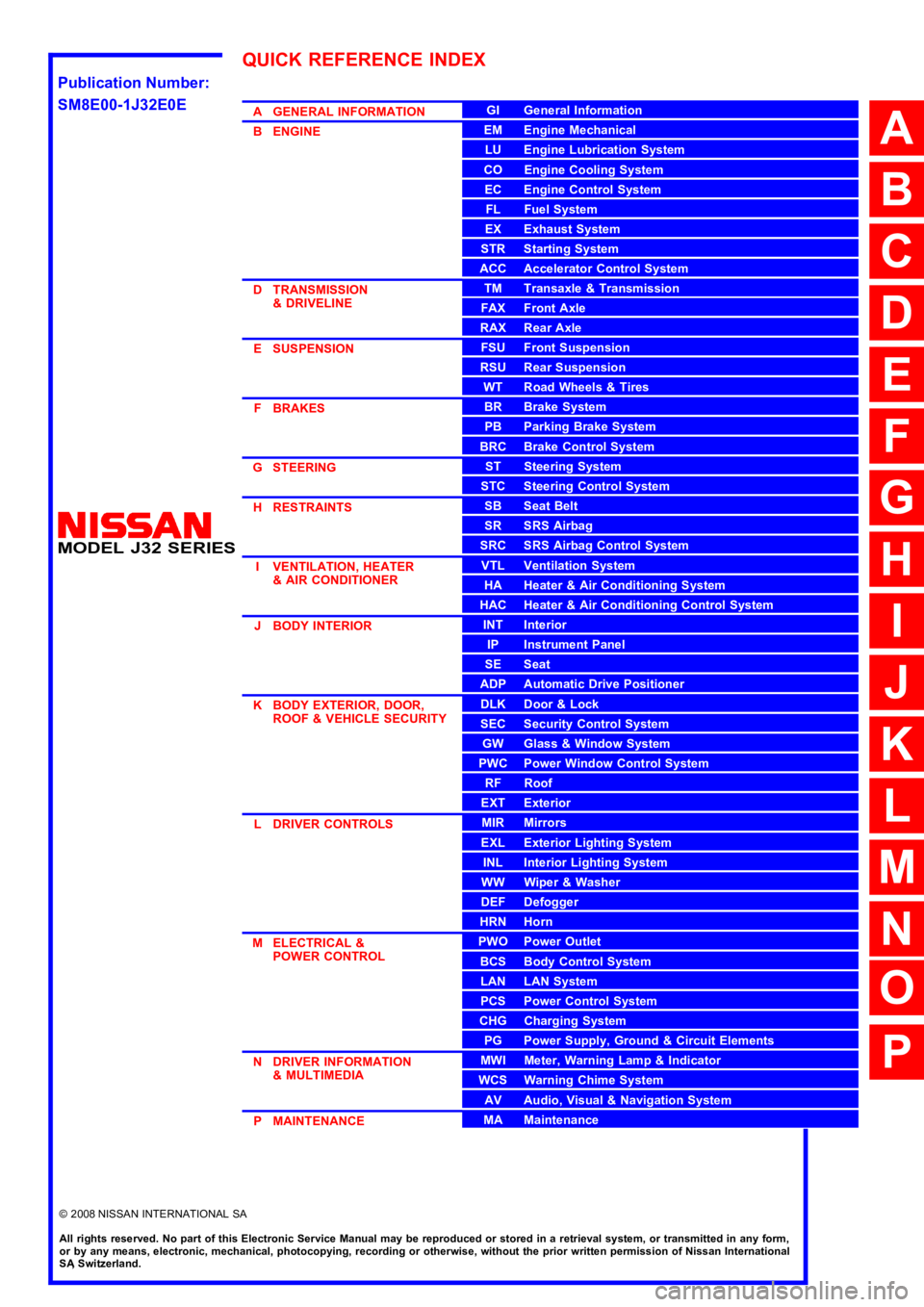
AGENERALINFORMATION
BENGINE
DTRANSMISSION&DRIVELINE
ESUSPENSION
FBRAKES
GSTEERING
HRESTRAINTS
IVENTILATION,HEATER&AIRCONDITIONER
JBODYINTERIOR
KBODYEXTERIOR,DOOR,ROOF&VEHICLESECURITY
LDRIVERCONTROLS
MELECTRICAL&POWERCONTROL
NDRIVERINFORMATION&MULTIMEDIA
PMAINTENANCE
GIGeneralInformation
EMEngineMechanical
LUEngineLubricationSystem
COEngineCoolingSystem
ECEngineControlSystem
FLFuelSystem
EXExhaustSystem
STRStartingSystem
ACCAcceleratorControlSystem
TMTransaxle &Transmission
FAXFrontAxle
RAXRearAxle
FSUFrontSuspension
RSURearSuspension
WTRoadWheels &Tires
BRBrakeSystem
PBParkingBrakeSystem
BRCBrakeControlSystem
STSteeringSystem
STCSteeringControlSystem
SBSeatBelt
SRSRSAirbag
SRCSRSAirbagControlSystem
VTLVentilationSystem
HAHeater &AirConditioningSystem
HACHeater &AirConditioningControlSystem
INTInterior
IPInstrumentPanel
SESeat
ADPAutomaticDrivePositioner
DLKDoor &Lock
SECSecurityControlSystem
GWGlass &WindowSystem
PWCPowerWindowControlSystem
RFRoof
EXTExterior
MIRMirrors
EXLExteriorLightingSystem
INLInteriorLightingSystem
WWWiper &Washer
DEFDefogger
HRNHorn
PWOPowerOutlet
BCSBodyControlSystem
LANLANSystem
PCSPowerControlSystem
CHGChargingSystem
PGPowerSupply,Ground&CircuitElements
MWIMeter,WarningLamp&Indicator
WCSWarningChimeSystem
AVAudio,Visual&NavigationSystem
MAMaintenance
QUICKREFERENCEINDEX
A
B
C
D
E
F
G
H
I
J
K
L
M
N
O
P
M
Publication Number:
SM8E00-1J32E0E
Page 9 of 5121

ADP-3
C
D
E
F
G
H
I
K
L
MA
B
ADP
N
O
P Diagnosis Procedure ..............................................
74
SEAT MEMORY INDICATOR ............................76
Description ..............................................................76
Component Function Check ..................................76
Diagnosis Procedure ..............................................76
Component Inspection ............................................77
BCM (BODY CONTROL MODULE) ...................78
Reference Value .....................................................78
Wiring Diagram - AUTOMATIC DRIVE POSI-
TIONER CONTROL SYSTEM - ............................
101
Fail-safe ................................................................107
DTC Inspection Priority Chart .............................109
DTC Index ............................................................110
ECU DIAGNOSIS .......................................112
DRIVER SEAT CONTROL UNIT ......................112
Reference Value ...................................................112
Wiring Diagram - AUTOMATIC DRIVE POSI-
TIONER CONTROL SYSTEM - ............................
117
Fail-safe ................................................................123
DTC Index ............................................................124
SYMPTOM DIAGNOSIS ............................125
MANUAL FUNCTION DOES NOT OPERATE ..125
ALL COMPONENTS ...............................................125
ALL COMPONENTS : Diagnosis Procedure .........125
SEAT SLIDING ........................................................125
SEAT SLIDING : Diagnosis Procedure .................125
SEAT RECLINING ...................................................126
SEAT RECLINING : Diagnosis Procedure ............126
SEAT LIFTING (FRONT) .........................................126
SEAT LIFTING (FRONT) : Diagnosis Procedure ..126
SEAT LIFTING (REAR) ...........................................127
SEAT LIFTING (REAR) : Diagnosis Procedure ....127
MEMORY FUNCTION DOES NOT OPERATE ..128
ALL COMPONENTS ...............................................128
ALL COMPONENTS : Diagnosis Procedure .........128
SEAT SLIDING ........................................................128
SEAT SLIDING : Diagnosis Procedure .................129
SEAT RECLINING ...................................................129
SEAT RECLINING : Diagnosis Procedure ............129
SEAT LIFTING (FRONT) .........................................129
SEAT LIFTING (FRONT) : Diagnosis Procedure ..129
SEAT LIFTING (REAR) ...........................................130
SEAT LIFTING (REAR) : Diagnosis Procedure .....130
MEMORY INDICATE DOES NOT OPERATE .131
Diagnosis Procedure .............................................131
ENTRY/EXIT ASSIST FUNCTION DOES NOT
OPERATE .......................................................
132
Diagnosis Procedure .............................................132
INTELLIGENT KEY INTERLOCK FUNCTION
DOES NOT OPERATE ....................................
133
Diagnosis Procedure .............................................133
NORMAL OPERATING CONDITION .............134
Description .............................................................134
PRECAUTION ............................................135
PRECAUTIONS ...............................................135
Precaution for Supplemental Restraint System
(SRS) "AIR BAG" and "SEAT BELT PRE-TEN-
SIONER" ...............................................................
135
ON-VEHICLE REPAIR ...............................136
DRIVER SEAT CONTROL UNIT ....................136
Exploded View .......................................................136
Removal and Installation .......................................136
SEAT MEMORY SWITCH ...............................137
Exploded View .......................................................137
Removal and Installation .......................................137
POWER SEAT SWITCH .................................138
Exploded View .......................................................138
Removal and Installation .......................................138
Page 11 of 5121

DIAGNOSIS AND REPAIR WORKFLOW
ADP-5
< BASIC INSPECTION >
C
D
E
F
G
H
I
K
L
MA
B
ADP
N
O
P
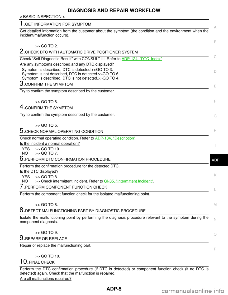
1.GET INFORMATION FOR SYMPTOM
Get detailed information from the customer about the symptom (the condition and the environment when the
incident/malfunction occurs).
>> GO TO 2.
2.CHECK DTC WITH AUTOMATIC DRIVE POSITIONER SYSTEM
Check “Self Diagnostic Result” with CONSULT-III. Refer to ADP-124, "
DTCIndex"
Are any symptoms described and any DTC displayed?
Symptom is described, DTC is detected.>>GO TO 3.
Symptom is not described, DTC is detected.>>GO TO 6.
Symptom is described, DTC is not detected.>>GO TO 4.
3.CONFIRM THE SYMPTOM
Try to confirm the symptom described by the customer.
>> GO TO 6.
4.CONFIRM THE SYMPTOM
Try to confirm the symptom described by the customer.
>> GO TO 5.
5.CHECK NORMAL OPERATING CONDITION
Check normal operating condition. Refer to ADP-134, "
Description".
Is the incident a normal operation?
YES >> GO TO 10.
NO >> GO TO 7.
6.PERFORM DTC CONFIRMATION PROCEDURE
Perform the confirmation procedure for the detected DTC.
Is the DTC displayed?
YES >> GO TO 8.
NO >> Check intermittent incident. Refer to GI-35, "
Intermittent Incident".
7.PERFORM COMPONENT FUNCTION CHECK
Perform the component function check for the isolated malfunctioning point.
>> GO TO 8.
8.DETECT MALFUNCTIONING PART BY DIAGNOSTIC PROCEDURE
Isolate the malfunctioning point by performing the diagnosis procedure relevant to the symptom during the
component diagnosis.
>> GO TO 9.
9.REPARE OR REPLACE
Repair or replace the malfunctioning part.
>> GO TO 10.
10.FINAL CHECK
Perform the DTC confirmation procedure (if DTC is detected) or component function check (if no DTC is
detected) again. Check that the malfunction is repaired.
Are all malfunctions repaired?
Page 13 of 5121

INSPECTION AND ADJUSTMENT
ADP-7
< BASIC INSPECTION >
C
D
E
F
G
H
I
K
L
MA
B
ADP
N
O
P
INSPECTION AND ADJUSTMENT
ADDITIONAL SERVICE WHEN REMOVING BATTERY NEGATIVE TERMINAL
ADDITIONAL SERVICE WHEN REMOVING BATTERY NEGATIVE TERMINAL : De-
scription
INFOID:0000000003759058
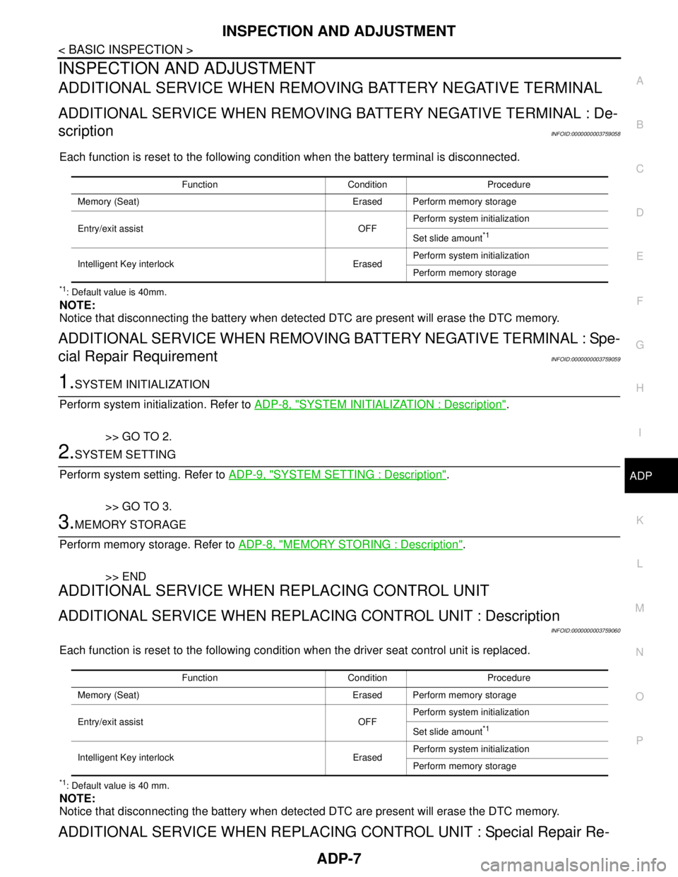
Each function is reset to the following condition when the battery terminal is disconnected.
*1: Default value is 40mm.
NOTE:
Notice that disconnecting the battery when detected DTC are present will erase the DTC memory.
ADDITIONAL SERVICE WHEN REMOVING BATTERY NEGATIVE TERMINAL : Spe-
cial Repair Requirement
INFOID:0000000003759059
1.SYSTEM INITIALIZATION
Perform system initialization. Refer to ADP-8, "
SYSTEM INITIALIZATION : Description".
>> GO TO 2.
2.SYSTEM SETTING
Perform system setting. Refer to ADP-9, "
SYSTEM SETTING : Description".
>> GO TO 3.
3.MEMORY STORAGE
Perform memory storage. Refer to ADP-8, "
MEMORY STORING : Description".
>> END
ADDITIONAL SERVICE WHEN REPLACING CONTROL UNIT
ADDITIONAL SERVICE WHEN REPLACING CONTROL UNIT : Description
INFOID:0000000003759060
Each function is reset to the following condition when the driver seat control unit is replaced.
*1: Default value is 40 mm.
NOTE:
Notice that disconnecting the battery when detected DTC are present will erase the DTC memory.
ADDITIONAL SERVICE WHEN REPLACING CONTROL UNIT : Special Repair Re-
Function Condition Procedure
Memory (Seat) Erased Perform memory storage
Entry/exit assist OFFPerform system initialization
Set slide amount
*1
Intelligent Key interlock ErasedPerform system initialization
Perform memory storage
Function Condition Procedure
Memory (Seat) Erased Perform memory storage
Entry/exit assist OFFPerform system initialization
Set slide amount
*1
Intelligent Key interlock ErasedPerform system initialization
Perform memory storage
Page 19 of 5121

AUTOMATIC DRIVE POSITIONER SYSTEM
ADP-13
< FUNCTION DIAGNOSIS >
C
D
E
F
G
H
I
K
L
MA
B
ADP
N
O
P
The seat control unit adopts the sleep mode to reduce the electric power consumption.
The sleep mode is activated when all of the following conditions are fulfilled.
1. Ignition switch turns OFF (Steering LOCK position)
2. No load is applied to the seat control
3. The seat control unit 45 seconds timer is not activated
4. Set switch and memory switch (1 and 2) turn OFF
WAKE-UP MODE
The sleep mode is cancelled when any status change is detected for the followings.
1. CAN communication
2. Power seat switch
3. Set switch and memory switch (1 and 2)
Page 22 of 5121

ADP-16
< FUNCTION DIAGNOSIS >
AUTOMATIC DRIVE POSITIONER SYSTEM
MANUAL FUNCTION
MANUAL FUNCTION : System DiagramINFOID:0000000003759072
MANUAL FUNCTION : System DescriptionINFOID:0000000003759073
OUTLINE
The driving position (seat) can be adjusted manually with power seat switch.
DETAIL FLOW
Seat
Item Function
Lifting motor (front) Moves the seat lifting (front) upward/downward
Lifting motor (rear) Moves the seat lifting (rear) upward/downward
Reclining motor Tilts and raises up the seatback
Sliding motor Slides the seat frontward/rearward
Memory indicator Illuminates or blinks according to the registration/operation status
JMJIA1813GB
Order Input Output Control unit condition
1Power seat switch
(sliding, lifting, reclin-
ing)—The power seat switch signal is inputted to the driver seat control
unit when the power seat switch is operated
2—Motors
(sliding, lifting, reclin-
ing)The driver seat control unit outputs signals to each motor accord-
ing to the power seat switch input signal
Page 25 of 5121

AUTOMATIC DRIVE POSITIONER SYSTEM
ADP-19
< FUNCTION DIAGNOSIS >
C
D
E
F
G
H
I
K
L
MA
B
ADP
N
O
P
MEMORY FUNCTION : System DiagramINFOID:0000000003759076
MEMORY FUNCTION : System DescriptionINFOID:0000000003759077
OUTLINE
The driver seat control unit can store the optimum driving positions (seat) for 2 people. If the front seat position
is changed, one-touch (pressing desired memory switch) operation allows changing to the other driving posi-
tion.
NOTE:
For further information for the memory storage procedure. Refer to ADP-8, "
MEMORY STORING : Descrip-
tion".
OPERATION PROCEDURE
1. Turn ignition switch ON
2. Shift select lever to the P position.
3. Press desired memory switch.
4. Driver seat will move to the memorized position.
OPERATION CONDITION
Satisfy all of the following items. The memory function is not performed if any of these items are not satisfied.
However, the memory operation can be performed for 45 seconds after opening the driver door (driver door switch OFF → ON) even if
the ignition switch position is in the OFF position.
DETAIL FLOW
JMJIA1814GB
Item Request status
Ignition positionON
Switch inputs
Power seat switch
Set switch
Memory switchOFF
(Not operated)
Selector leverP position
Vehicle speed0 km/h (0 MPH)
Page 26 of 5121

ADP-20
< FUNCTION DIAGNOSIS >
AUTOMATIC DRIVE POSITIONER SYSTEM
Order Input Output Control unit condition
1 Memory switch —The memory switch signal is inputted to the driver seat control unit
when memory switch 1 or 2 is operated
2—Motors
(Seat)Driver seat control unit operates each motor of seat when it recogniz-
es the memory switch has been pressed for 0.5 seconds or more and
requests each motor operation
Memory switch Indica-
torDriver seat control unit requests the blinking of memory indicator
while either of the motors are operating. The driver seat control unit
illuminates the memory indicator
3Sensors
(Seat)—Driver seat control unit judges the operating seat position with each
seat sensor input. Driver seat control unit stops the operation of each
motor when each part reaches the recorded address
4—Memory switch Indica-
torDriver seat control unit requests the illumination of memory indicator
after all motors stop. The driver seat control unit illuminates the mem-
ory indicator for 5 seconds
Page 29 of 5121

AUTOMATIC DRIVE POSITIONER SYSTEM
ADP-23
< FUNCTION DIAGNOSIS >
C
D
E
F
G
H
I
K
L
MA
B
ADP
N
O
P
EXIT ASSIST FUNCTION : System DiagramINFOID:0000000003759080
EXIT ASSIST FUNCTION : System DescriptionINFOID:0000000003759081
OUTLINE
When opening the driver door while the operation condition is satisfied, the seat moves backward 40 mm
(1.57 in) from normal sitting position.
The seat slide amount operation at entry/exit operation can be changed.
NOTE:
This function is set to ON before delivery (initial setting).
Further information for the system setting procedure. Refer to ADP-8, "
SYSTEM INITIALIZATION : Descrip-
tion".
OPERATION PROCEDURE
1. Open the driver door with ignition switch in the OFF position.(Intelligent Key is not inserted into key slot)
2. Driver seat moves to the exiting position.
OPERATION CONDITION
Satisfy all of the following items. The exit assist function is not performed if any of these items are not satisfied.
JMJIA1816GB
Item Request status
Ignition positionOFF
System setting [Entry/exit assist function (seat)] ON
InitializationDone
Key switchOFF
(Intelligent Key is not inserted into key slot)
Switch inputs
Power seat switch
Set switch
Memory switchOFF
(Not operated)
Selector leverP position
BCMHandle position
Page 30 of 5121

ADP-24
< FUNCTION DIAGNOSIS >
AUTOMATIC DRIVE POSITIONER SYSTEM
DETAIL FLOW
Order Input Output Control unit condition
1Door switch
(Driver side)—Driver seat control unit receives door switch signal (driver side/
open) from BCM via CAN communication
2 — Sliding motorDriver seat control unit operates the seat sliding motor, which recog-
nizes that the driver side door is opened with ignition switch OFF