Wheel nut NISSAN TEANA 2008 Service Manual
[x] Cancel search | Manufacturer: NISSAN, Model Year: 2008, Model line: TEANA, Model: NISSAN TEANA 2008Pages: 5121, PDF Size: 69.03 MB
Page 909 of 5121
FRONT DISC BRAKE
BR-13
< ON-VEHICLE MAINTENANCE >
C
D
E
G
H
I
J
K
L
MA
B
BR
N
O
P
FRONT DISC BRAKE
BRAKE PAD
BRAKE PAD : Inspection and AdjustmentINFOID:0000000003811179
INSPECTION
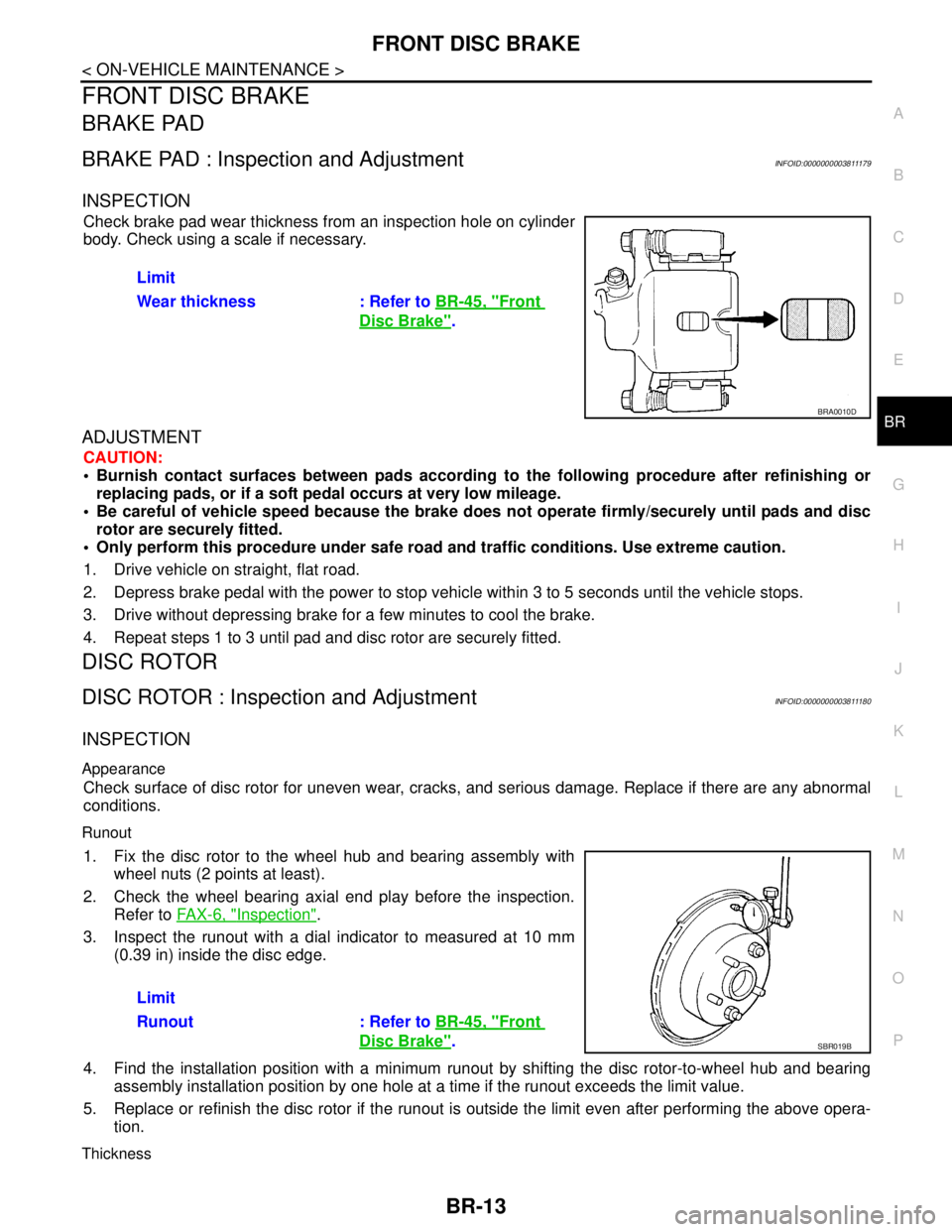
Check brake pad wear thickness from an inspection hole on cylinder
body. Check using a scale if necessary.
ADJUSTMENT
CAUTION:
Burnish contact surfaces between pads according to the following procedure after refinishing or
replacing pads, or if a soft pedal occurs at very low mileage.
Be careful of vehicle speed because the brake does not operate firmly/securely until pads and disc
rotor are securely fitted.
Only perform this procedure under safe road and traffic conditions. Use extreme caution.
1. Drive vehicle on straight, flat road.
2. Depress brake pedal with the power to stop vehicle within 3 to 5 seconds until the vehicle stops.
3. Drive without depressing brake for a few minutes to cool the brake.
4. Repeat steps 1 to 3 until pad and disc rotor are securely fitted.
DISC ROTOR
DISC ROTOR : Inspection and AdjustmentINFOID:0000000003811180
INSPECTION
Appearance
Check surface of disc rotor for uneven wear, cracks, and serious damage. Replace if there are any abnormal
conditions.
Runout
1. Fix the disc rotor to the wheel hub and bearing assembly with
wheel nuts (2 points at least).
2. Check the wheel bearing axial end play before the inspection.
Refer to FA X - 6 , "
Inspection".
3. Inspect the runout with a dial indicator to measured at 10 mm
(0.39 in) inside the disc edge.
4. Find the installation position with a minimum runout by shifting the disc rotor-to-wheel hub and bearing
assembly installation position by one hole at a time if the runout exceeds the limit value.
5. Replace or refinish the disc rotor if the runout is outside the limit even after performing the above opera-
tion.
Thickness
Limit
Wear thickness : Refer to BR-45, "
Front
Disc Brake".
BRA0010D
Limit
Runout : Refer to BR-45, "
Front
Disc Brake".SBR019B
Page 911 of 5121
REAR DISC BRAKE
BR-15
< ON-VEHICLE MAINTENANCE >
C
D
E
G
H
I
J
K
L
MA
B
BR
N
O
P
REAR DISC BRAKE
BRAKE PAD
BRAKE PAD : Inspection and AdjustmentINFOID:0000000003811181
INSPECTION
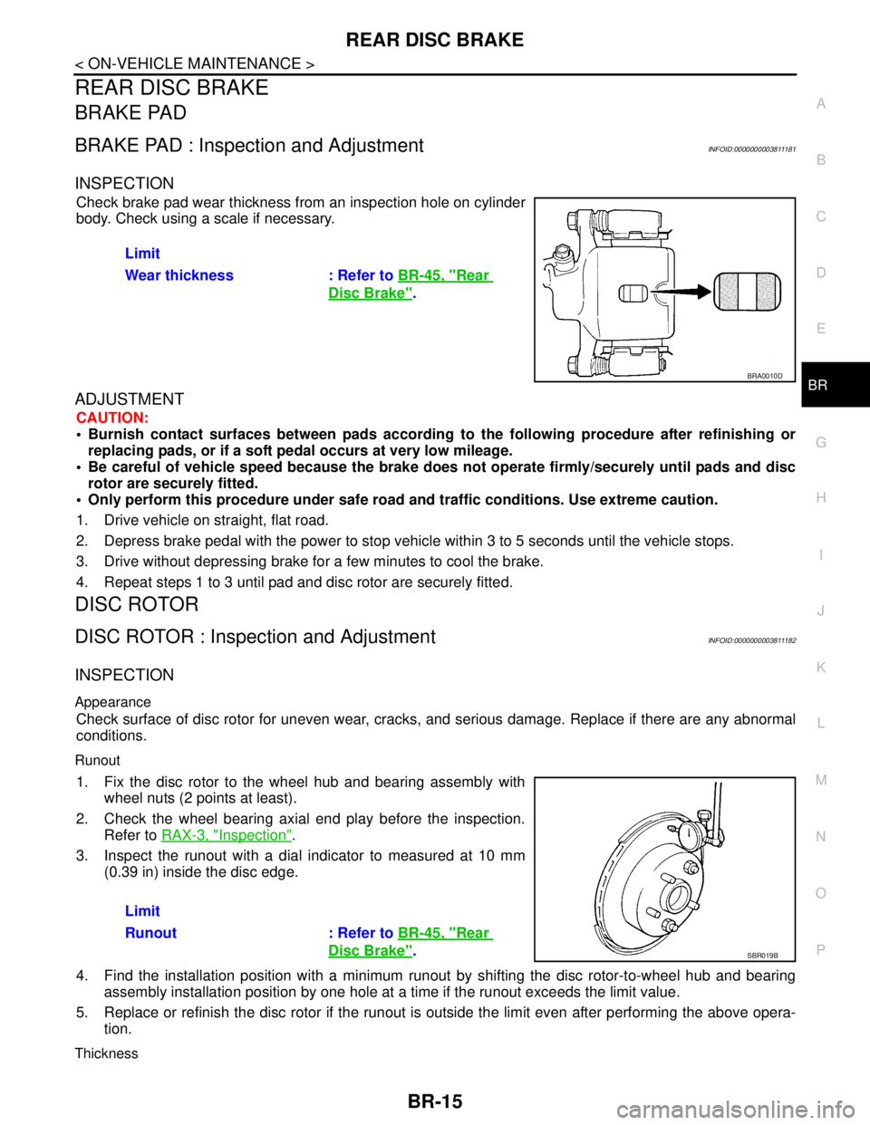
Check brake pad wear thickness from an inspection hole on cylinder
body. Check using a scale if necessary.
ADJUSTMENT
CAUTION:
Burnish contact surfaces between pads according to the following procedure after refinishing or
replacing pads, or if a soft pedal occurs at very low mileage.
Be careful of vehicle speed because the brake does not operate firmly/securely until pads and disc
rotor are securely fitted.
Only perform this procedure under safe road and traffic conditions. Use extreme caution.
1. Drive vehicle on straight, flat road.
2. Depress brake pedal with the power to stop vehicle within 3 to 5 seconds until the vehicle stops.
3. Drive without depressing brake for a few minutes to cool the brake.
4. Repeat steps 1 to 3 until pad and disc rotor are securely fitted.
DISC ROTOR
DISC ROTOR : Inspection and AdjustmentINFOID:0000000003811182
INSPECTION
Appearance
Check surface of disc rotor for uneven wear, cracks, and serious damage. Replace if there are any abnormal
conditions.
Runout
1. Fix the disc rotor to the wheel hub and bearing assembly with
wheel nuts (2 points at least).
2. Check the wheel bearing axial end play before the inspection.
Refer to RAX-3, "
Inspection".
3. Inspect the runout with a dial indicator to measured at 10 mm
(0.39 in) inside the disc edge.
4. Find the installation position with a minimum runout by shifting the disc rotor-to-wheel hub and bearing
assembly installation position by one hole at a time if the runout exceeds the limit value.
5. Replace or refinish the disc rotor if the runout is outside the limit even after performing the above opera-
tion.
Thickness
Limit
Wear thickness : Refer to BR-45, "
Rear
Disc Brake".
BRA0010D
Limit
Runout : Refer to BR-45, "
Rear
Disc Brake".SBR019B
Page 917 of 5121
BRAKE PIPINGBR-21
< ON-VEHICLE REPAIR >
C
DE
G H
I
J
K L
M A
B
BR
N
O P
FRONT : Removal and InstallationINFOID:0000000003811188
REMOVAL
CAUTION:
Never spill or splash brake fluid on painted surfaces. Brake fluid may seriously damage paint. Wipe it
off immediately and wash with wate r if it gets on a painted surface.
1. Remove tires.
2. Drain brake fluid. Refer to BR-9, "
Draining".
3. Loosen the flare nut with a flare nut wrenc h and separate the brake tube from the hose.
CAUTION:
Never scratch the flare nut and the brake tube.
Never bend sharply, twist or strong ly pull out the brake hoses and tubes.
Cover open end of brake tub es and hoses when disconnecting to prevent entrance of dirt.
4. Remove the union bolt and copper washers, and remove the brake hose from the brake caliper assembly.
5. Remove the lock plate and remove the brake hose.
INSTALLATION
CAUTION:
Never spill or splash brake fluid on painted surfaces. Brake fluid may seriously damage paint. Wipe it
off immediately and wash with wate r if it gets on a painted surface.
1. Assemble the union bolt and the copper washers to the brake hose. CAUTION:
Never reuse the copper washer.
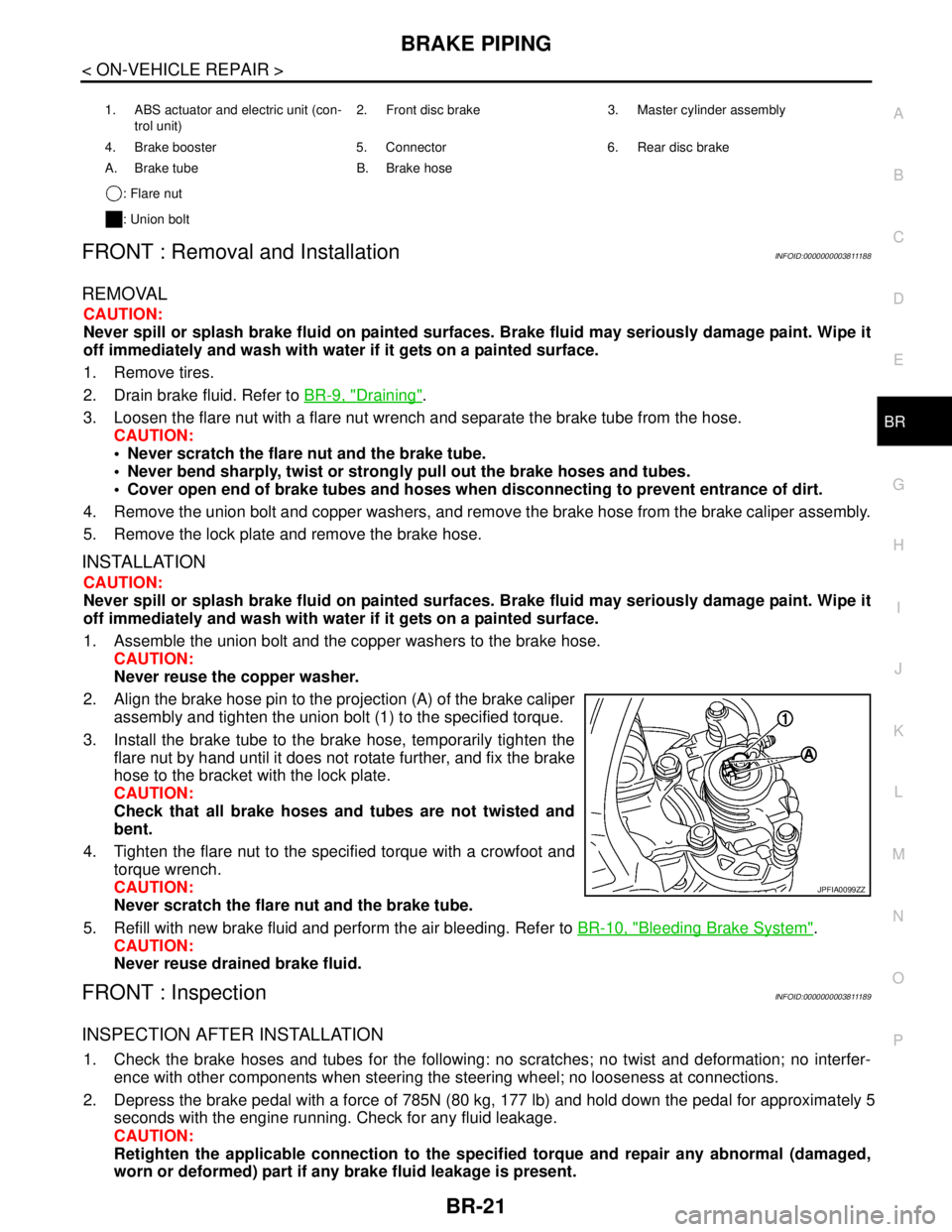
2. Align the brake hose pin to the projection (A) of the brake caliper assembly and tighten the union bolt (1) to the specified torque.
3. Install the brake tube to the brake hose, temporarily tighten the flare nut by hand until it does not rotate further, and fix the brake
hose to the bracket with the lock plate.
CAUTION:
Check that all brake hoses and tubes are not twisted and
bent.
4. Tighten the flare nut to the specified torque with a crowfoot and torque wrench.
CAUTION:
Never scratch the flare nut and the brake tube.
5. Refill with new brake fluid and perform the air bleeding. Refer to BR-10, "
Bleeding Brake System".
CAUTION:
Never reuse drained brake fluid.
FRONT : InspectionINFOID:0000000003811189
INSPECTION AFTER INSTALLATION
1. Check the brake hoses and tubes for the following: no scratches; no twist and deformation; no interfer-
ence with other components when steering the steering wheel; no looseness at connections.
2. Depress the brake pedal with a force of 785N (80 kg, 177 lb) and hold down the pedal for approximately 5
seconds with the engine running. Check for any fluid leakage.
CAUTION:
Retighten the applicable connect ion to the specified torque and repair any abnormal (damaged,
worn or deformed) part if any brake fluid leakage is present.
1. ABS actuator and electric unit (con-
trol unit) 2. Front disc brake 3. Master cylinder assembly
4. Brake booster 5. Connector 6. Rear disc brake
A. Brake tube B. Brake hose : Flare nut
: Union bolt
JPFIA0099ZZ
Page 919 of 5121

BRAKE PIPINGBR-23
< ON-VEHICLE REPAIR >
C
DE
G H
I
J
K L
M A
B
BR
N
O P
REAR : Removal and InstallationINFOID:0000000003811192
REMOVAL
CAUTION:
Never spill or splash brake fluid on painted surfaces. Brake fluid may seriously damage paint. Wipe it
off immediately and wash with wate r if it gets on a painted surface.
1. Remove tires.
2. Drain brake fluid. Refer to BR-9, "
Draining".
3. Loosen the flare nut with a flare nut wrenc h and separate the brake tube from the hose.
CAUTION:
Never scratch the flare nut and the brake tube.
Never sharply bend, twist or strongly pull the brake hoses and tubes.
Cover the open end of brake tubes and hoses wh en disconnecting to prevent entrance of dirt.
4. Remove the union bolt and copper washers, and remove the brake hose from the brake caliper assembly.
5. Remove the lock plate and remove the brake hose from the vehicle.
INSTALLATION
CAUTION:
Never spill or splash brake fluid on painted surfaces. Brake fluid may seriously damage paint. Wipe it
off immediately and wash with wate r if it gets on a painted surface.
1. Assemble the union bolt and the copper washers to the brake hose. CAUTION:
Never reuse copper washer.
2. Install the brake hose L-pin by aligning it with the brake caliper assembly positioning hole, and tighten the union bolt (1) to the
specified torque.
3. Connect the hose to the brake tube, temporarily tighten the flare nut by hand until it does not rotate further, and fix the brake hose
to the bracket with the lock plate.
CAUTION:
Check that the brake hoses and tubes are not twisted and
bent.
4. Tighten the flare nut to the specified torque with a crowfoot and torque wrench.
CAUTION:
Never scratch the flare nut and the brake tube.
5. Refill with new brake fluid and perform the air bleeding. Refer to BR-10, "
Bleeding Brake System".
CAUTION:
Never reuse drained brake fluid.
REAR : InspectionINFOID:0000000003811193
INSPECTION AFTER INSTALLATION
1. Check the brake hoses and tubes for the following: no scratches; no twist and deformation; no interfer-
ence with other components when steering the steering wheel; no looseness at connections.
2. Depress the brake pedal with a force of 785N (80
kg, 177 lb) and hold down the pedal for approximately 5
seconds with the engine running. Check for any fluid leakage.
CAUTION:
1. ABS actuator and electric unit (con- trol unit) 2. Front disc brake 3. Master cylinder assembly
4. Brake booster 5. Connector 6. Rear disc brake
A. Brake tube B. Brake hose : Flare nut
: Union bolt
JPFIA0012ZZ
Page 932 of 5121
BR-36
< ON-VEHICLE REPAIR >
FRONT DISC BRAKE
CAUTION:
Never depress the brake pedal. Brake fluid may splash while removing the brake hose.
1. Remove tires.
2. Fix the disc rotor using wheel nuts.
3. Drain brake fluid. Refer to BR-9, "
Draining".
CAUTION:
Never spill or splash brake fluid on the disc rotor.
4. Remove union bolt and copper washers, and then disconnect brake hose from caliper assembly. Refer to
BR-19, "
FRONT : Exploded View".
5. Remove torque member mounting bolts, and remove brake caliper assembly.
CAUTION:
Never drop brake pads and caliper assembly.
6. Remove disc rotor.
CAUTION:
Put matching marks on the wheel hub and bearing assembly and the disc rotor before removing
the disc rotor.
Never drop disc rotor.
INSTALLATION
WARNING:
Clean any dust from the brake caliper and brake pads with a vacuum dust collector. Never blow with
compressed air.
CAUTION:
Never depress the brake pedal. Brake fluid may splash while removing the brake hose.
1. Install disc rotor.
CAUTION:
Align the matching marks put during removal when reusing the disc rotor.
2. Install the brake caliper assembly to the vehicle and tighten the torque member mounting bolts to the
specified torque.
CAUTION:
Never spill or splash any grease and moisture on the brake caliper assembly mounting face,
threads, mounting bolts and washers. Wipe out any grease and moisture.
3. Install brake hose and copper washers to brake caliper assembly, and tighten union bolts to the specified
torque. Refer to BR-19, "
FRONT : Exploded View".
CAUTION:
Never reuse copper washer.
4. Refill with new brake fluid and perform the air bleeding. Refer to BR-10, "
Bleeding Brake System".
CAUTION:
Never reuse drained brake fluid.
Never spill or splash brake fluid on the disc rotor.
5. Check a drag of front disc brake. If any drag is found, refer to BR-38, "
BRAKE CALIPER ASSEMBLY :
Inspection".
BRAKE CALIPER ASSEMBLY : Disassembly and AssemblyINFOID:0000000003811209
DISASSEMBLY
NOTE:
Never remove the torque member and pad retainers when disassembling and assembling the cylinder body.
1. Remove the sliding pin bolts, and remove the cylinder body from the torque member.
CAUTION:
Never drop brake pads, shims, shim cover and pad retainers from torque member.
2. Remove brake pads, shims and shim cover. Refer to BR-33, "
BRAKE PAD : Exploded View".
3. Remove sliding pins and sliding pin boots from torque member.
4. Remove bushing from sliding pin.
Page 938 of 5121
BR-42
< ON-VEHICLE REPAIR >
REAR DISC BRAKE
Clean any dust from the brake caliper and brake pads with a vacuum dust collector. Never blow with
compressed air.
CAUTION:
Never depress the brake pedal. Brake fluid may splash while removing the brake hose.
1. Remove tires.
2. Fix the disc rotor using wheel nuts.
3. Drain brake fluid. Refer to BR-9, "
Draining".
CAUTION:
Never spill or splash brake fluid on the disc rotor.
4. Remove union bolt and copper washers then disconnect brake hose from caliper assembly.
5. Remove torque member mounting bolts, and remove brake caliper assembly.
CAUTION:
Never drop brake pads and caliper assembly.
6. Remove disc rotor.
CAUTION:
Put matching marks on the wheel hub and bearing assembly and the disc rotor before removing
the disc rotor.
Never drop disc rotor.
INSTALLATION
WARNING:
Clean any dust from the brake caliper and brake pads with a vacuum dust collector. Never blow with
compressed air.
CAUTION:
Never depress the brake pedal. Brake fluid may splash while removing the brake hose.
1. Install disc rotor.
CAUTION:
Align the matching marks put during removal when reusing the disc rotor.
2. Install the brake caliper assembly to the vehicle and tighten the torque member mounting bolts to the
specified torque.
CAUTION:
Never spill or splash any grease and moisture on the brake caliper assembly mounting face,
threads, mounting bolts, and washers. Wipe out any grease and moisture.
3. Install brake hose and copper washers to brake caliper assembly, and tighten union bolts to the specified
torque. Refer to BR-22, "
REAR : Exploded View".
CAUTION:
Never reuse copper washer.
4. Refill with new brake fluid and perform the air bleeding. Refer to BR-10, "
Bleeding Brake System".
CAUTION:
Never reuse drained brake fluid.
Never spill or splash brake fluid on the disc rotor.
5. Check that no drag feel is present for the rear disc brake. Refer to BR-44, "
BRAKE CALIPER ASSEMBLY
: Inspection".
BRAKE CALIPER ASSEMBLY : Disassembly and AssemblyINFOID:0000000003811216
DISASSEMBLY
NOTE:
Never remove the torque member and pad retainers when disassembling and assembling the cylinder body.
1. Remove the sliding pin bolts and remove the cylinder body from the torque member.
2. Remove brake pads and shims. Refer to BR-39, "
BRAKE PAD : Exploded View".
3. Remove sliding pin boots from torque member.
4. Remove bushing from sliding pin bolt.
Page 954 of 5121
![NISSAN TEANA 2008 Service Manual DIAGNOSIS SYSTEM [ABS ACTUATOR AND ELECTRIC UNIT (CONTROL
UNIT)]
BRC-13
< FUNCTION DIAGNOSIS >[ABS]
C
D
E
G
H
I
J
K
L
MA
B
BRC
N
O
P
DIAGNOSIS SYSTEM [ABS ACTUATOR AND ELECTRIC UNIT (CONTROL
UNIT)]
C](/img/5/57391/w960_57391-953.png "NISSAN TEANA 2008 Service Manual DIAGNOSIS SYSTEM [ABS ACTUATOR AND ELECTRIC UNIT (CONTROL
UNIT)]
BRC-13
< FUNCTION DIAGNOSIS >[ABS]
C
D
E
G
H
I
J
K
L
MA
B
BRC
N
O
P
DIAGNOSIS SYSTEM [ABS ACTUATOR AND ELECTRIC UNIT (CONTROL
UNIT)]
C")
DIAGNOSIS SYSTEM [ABS ACTUATOR AND ELECTRIC UNIT (CONTROL
UNIT)]
BRC-13
< FUNCTION DIAGNOSIS >[ABS]
C
D
E
G
H
I
J
K
L
MA
B
BRC
N
O
P
DIAGNOSIS SYSTEM [ABS ACTUATOR AND ELECTRIC UNIT (CONTROL
UNIT)]
CONSULT-III FunctionINFOID:0000000003766730
FUNCTION
CONSULT-III can display each diagnostic item using the diagnostic test modes shown following.
SELF DIAGNOSTIC RESULT
Operation Procedure
Before performing the self-diagnosis, start engine and drive vehicle at 30 km/h (19 MPH) or more for approxi-
mately 1 minute.
Display Item List
Refer to BRC-48, "DTC No. Index".
How to Erase Self-diagnosis Results
After erasing DTC memory, start the engine and drive the vehicle at 30 km/h (19 MPH) or more for approxi-
mately 1 minute as the final inspection, and make sure that the ABS warning lamp and brake warning lamp
turn OFF.
CAUTION:
If memory cannot be erased, perform applicable diagnosis.
NOTE:
When the wheel sensor malfunctions, after inspecting the wheel sensor system, ABS warning lamp and
brake warning lamp will not turn OFF even when the system is normal unless the vehicle is driven at approx-
imately 30 km/h (19 MPH) or more for approximately 1 minute.
Brake warning lamp will turn ON in case of parking brake operation (when switch is ON) or in case of brake
fluid level switch operation (when brake fluid is insufficient).
DATA MONITOR
Display Item List
×: Applicable : Optional item
Diagnostic test mode Function
Self diagnostic result Self-diagnostic results can be read and erased quickly.
Data monitor Input/Output data in the ABS actuator and electric unit (control unit) can be read.
Active testCONSULT-III drives some actuators apart from ABS actuator and electric unit (control unit) and
also shifts some parameters in a specified range.
ECU identification ABS actuator and electric unit (control unit) part number can be read.
Monitor item (Unit)SELECT MONITOR ITEM
Remarks
ECU INPUT
SIGNALSMAIN SIGNALS
FR LH SENSOR
[km/h (MPH)]××Wheel speed calculated by front LH wheel sensor signal
FR RH SENSOR
[km/h (MPH)]××Wheel speed calculated by front RH wheel sensor signal
RR LH SENSOR
[km/h (MPH)]××Wheel speed calculated by rear LH wheel sensor signal
RR RH SENSOR
[km/h (MPH)]××Wheel speed calculated by rear RH wheel sensor signal
STOP LAMP SW
(On/Off)××Stop lamp switch signal status
BATTERY VOLT
(V)××Battery voltage supplied to the ABS actuator and electric
unit (control unit)
Page 957 of 5121
![NISSAN TEANA 2008 Service Manual BRC-16
< COMPONENT DIAGNOSIS >[ABS]
C1101, C1102, C1103, C1104 WHEEL SENSOR
COMPONENT DIAGNOSIS
C1101, C1102, C1103, C1104 WHEEL SENSOR
DescriptionINFOID:0000000003766731
When the sensor rotor rotates](/img/5/57391/w960_57391-956.png "NISSAN TEANA 2008 Service Manual BRC-16
< COMPONENT DIAGNOSIS >[ABS]
C1101, C1102, C1103, C1104 WHEEL SENSOR
COMPONENT DIAGNOSIS
C1101, C1102, C1103, C1104 WHEEL SENSOR
DescriptionINFOID:0000000003766731
When the sensor rotor rotates")
BRC-16
< COMPONENT DIAGNOSIS >[ABS]
C1101, C1102, C1103, C1104 WHEEL SENSOR
COMPONENT DIAGNOSIS
C1101, C1102, C1103, C1104 WHEEL SENSOR
DescriptionINFOID:0000000003766731
When the sensor rotor rotates, the magnetic field changes. Wheel sensor converts the magnetic field changes
to current signals (rectangular wave) and transmits them to the ABS actuator and electric unit (control unit).
DTC LogicINFOID:0000000003766732
DTC DETECTION LOGIC
DTC CONFIRMATION PROCEDURE
1.DTC REPRODUCTION PROCEDURE
1. Start the engine and drive the vehicle at 30 km/h (19 MPH) or more for approximately 1 minute.
2. Perform ABS actuator and electric unit (control unit) self-diagnosis.
Is DTC
“C1101”, “C1102”, “C1103” or “C1104” detected?
YES >> Proceed to diagnosis. Refer to BRC-16, "Diagnosis Procedure".
NO >> INSPECTION END
Diagnosis ProcedureINFOID:0000000003766733
CAUTION:
Do not check between wheel sensor terminals.
1.CHECK TIRES
Check air pressure, wear and size. Refer to WT-5, "
Tire Air Pressure".
Is the inspection result normal?
YES >> GO TO 2.
NO >> Repair or replace damaged parts.
2.CHECK SENSOR AND SENSOR ROTOR
Check sensor rotor for damage.
Check wheel sensor for damage, disconnection or looseness.
Is the inspection result normal?
YES >> GO TO 3.
NO >> Repair wheel sensor mount or replace sensor rotor. Then perform the self-diagnosis.
3.CHECK CONNECTOR
1. Turn the ignition switch OFF.
2. Disconnect ABS actuator and electric unit (control unit) connector.
3. Disconnect malfunctioning wheel sensor connector.
4. Check terminal to see if it is deformed, disconnected, looseness, etc.
Is the inspection result normal?
YES >> GO TO 4.
NO >> Repair or replace damaged parts.
DTC Display item Malfunction detected condition Possible cause
C1101 RR RH SENSOR-1Circuit of rear RH wheel sensor is open. Or when the sen-
sor power voltage is outside the standard.
Harness or connector
Wheel sensor
ABS actuator and electric unit
(control unit) C1102 RR LH SENSOR-1Circuit of rear LH wheel sensor is open. Or when the sen-
sor power voltage is outside the standard.
C1103 FR RH SENSOR-1Circuit of front RH wheel sensor is open. Or when the
sensor power voltage is outside the standard.
C1104 FR LH SENSOR-1Circuit of front LH wheel sensor is open. Or when the
sensor power voltage is outside the standard.
Page 960 of 5121
![NISSAN TEANA 2008 Service Manual C1105, C1106, C1107, C1108 WHEEL SENSOR
BRC-19
< COMPONENT DIAGNOSIS >[ABS]
C
D
E
G
H
I
J
K
L
MA
B
BRC
N
O
P
C1105, C1106, C1107, C1108 WHEEL SENSOR
DescriptionINFOID:0000000003767288
When the sensor](/img/5/57391/w960_57391-959.png "NISSAN TEANA 2008 Service Manual C1105, C1106, C1107, C1108 WHEEL SENSOR
BRC-19
< COMPONENT DIAGNOSIS >[ABS]
C
D
E
G
H
I
J
K
L
MA
B
BRC
N
O
P
C1105, C1106, C1107, C1108 WHEEL SENSOR
DescriptionINFOID:0000000003767288
When the sensor")
C1105, C1106, C1107, C1108 WHEEL SENSOR
BRC-19
< COMPONENT DIAGNOSIS >[ABS]
C
D
E
G
H
I
J
K
L
MA
B
BRC
N
O
P
C1105, C1106, C1107, C1108 WHEEL SENSOR
DescriptionINFOID:0000000003767288
When the sensor rotor rotates, the magnetic field changes. Wheel sensor converts the magnetic field changes
to current signals (rectangular wave) and transmits them to the ABS actuator and electric unit (control unit).
DTC LogicINFOID:0000000003766737
DTC DETECTION LOGIC
DTC CONFIRMATION PROCEDURE
1.DTC REPRODUCTION PROCEDURE
1. Start the engine and drive the vehicle at 30 km/h (19 MPH) or more for approximately 1 minute.
2. Perform ABS actuator and electric unit (control unit) self-diagnosis.
Is DTC
“C1105”, “C1106”, “C1107” or “C1108” detected?
YES >> Proceed to diagnosis. Refer to BRC-19, "Diagnosis Procedure".
NO >> INSPECTION END
Diagnosis ProcedureINFOID:0000000003767289
CAUTION:
Do not check between wheel sensor terminals.
1.CHECK TIRES
Check air pressure, wear and size. Refer to WT-5, "
Tire Air Pressure".
Is the inspection result normal?
YES >> GO TO 2.
NO >> Repair or replace damaged parts.
2.CHECK SENSOR AND SENSOR ROTOR
Check sensor rotor for damage.
Check wheel sensor for damage, disconnection or looseness.
Is the inspection result normal?
YES >> GO TO 3.
NO >> Repair wheel sensor mount or replace sensor rotor. Then perform the self-diagnosis.
3.CHECK CONNECTOR
1. Turn the ignition switch OFF.
2. Disconnect ABS actuator and electric unit (control unit) connector.
3. Disconnect malfunctioning wheel sensor connector.
DTC Display item Malfunction detected condition Possible cause
C1105 RR RH SENSOR-2When the circuit in the rear RH wheel sensor is short-cir-
cuited. Or when the distance between the wheel sensor
and sensor rotor is too large and the sensor pulse cannot
be recognized by the control unit.
Harness or connector
Wheel sensor
ABS actuator and electric unit
(control unit) C1106 RR LH SENSOR-2When the circuit in the rear LH wheel sensor is short-cir-
cuited. Or when the distance between the wheel sensor
and sensor rotor is too large and the sensor pulse cannot
be recognized by the control unit.
C1107 FR RH SENSOR-2When the circuit in the front RH wheel sensor is short-cir-
cuited. Or when the distance between the wheel sensor
and sensor rotor is too large and the sensor pulse cannot
be recognized by the control unit.
C1108 FR LH SENSOR-2When the circuit in the front LH wheel sensor is short-cir-
cuited. Or when the distance between the wheel sensor
and sensor rotor is too large and the sensor pulse cannot
be recognized by the control unit.
Page 968 of 5121
![NISSAN TEANA 2008 Service Manual C1115 WHEEL SENSOR
BRC-27
< COMPONENT DIAGNOSIS >[ABS]
C
D
E
G
H
I
J
K
L
MA
B
BRC
N
O
P
C1115 WHEEL SENSOR
DescriptionINFOID:0000000003767292
When the sensor rotor rotates, the magnetic field changes.](/img/5/57391/w960_57391-967.png "NISSAN TEANA 2008 Service Manual C1115 WHEEL SENSOR
BRC-27
< COMPONENT DIAGNOSIS >[ABS]
C
D
E
G
H
I
J
K
L
MA
B
BRC
N
O
P
C1115 WHEEL SENSOR
DescriptionINFOID:0000000003767292
When the sensor rotor rotates, the magnetic field changes.")
C1115 WHEEL SENSOR
BRC-27
< COMPONENT DIAGNOSIS >[ABS]
C
D
E
G
H
I
J
K
L
MA
B
BRC
N
O
P
C1115 WHEEL SENSOR
DescriptionINFOID:0000000003767292
When the sensor rotor rotates, the magnetic field changes. Wheel sensor converts the magnetic field changes
to current signals (rectangular wave) and transmits them to the ABS actuator and electric unit (control unit).
DTC LogicINFOID:0000000003766759
DTC DETECTION LOGIC
DTC CONFIRMATION PROCEDURE
1.DTC REPRODUCTION PROCEDURE
1. Start the engine and drive the vehicle at 30 km/h (19 MPH) or more for approximately 1 minute.
2. Perform ABS actuator and electric unit (control unit) self-diagnosis.
Is DTC
“C 111 5” detected?
YES >> Proceed to diagnosis. Refer to BRC-27, "Diagnosis Procedure".
NO >> INSPECTION END
Diagnosis ProcedureINFOID:0000000003767293
CAUTION:
Do not check between wheel sensor terminals.
1.CHECK TIRES
Check air pressure, wear and size. Refer to WT-5, "
Tire Air Pressure".
Is the inspection result normal?
YES >> GO TO 2.
NO >> Repair or replace damaged parts.
2.CHECK SENSOR AND SENSOR ROTOR
Check sensor rotor for damage.
Check wheel sensor for damage, disconnection or looseness.
Is the inspection result normal?
YES >> GO TO 3.
NO >> Repair wheel sensor mount or replace sensor rotor. Then perform the self-diagnosis.
3.CHECK CONNECTOR
1. Turn the ignition switch OFF.
2. Disconnect ABS actuator and electric unit (control unit) connector.
3. Disconnect malfunctioning wheel sensor connector.
4. Check terminal to see if it is deformed, disconnected, looseness, etc.
Is the inspection result normal?
YES >> GO TO 4.
NO >> Repair or replace damaged parts.
4.CHECK WHEEL SENSOR HARNESS
1. Check the continuity between ABS actuator and electric unit (control unit) harness connector and wheel
sensor harness connector. (Also check continuity when steering wheel is turned right and left and when
sensor harness inside the wheel house is moved.)
DTC Display item Malfunction detected condition Possible cause
C 111 5ABS SENSOR
[ABNORMAL SIGNAL]When wheel sensor input signal is malfunctioning. Harness or connector
Wheel sensor
ABS actuator and electric unit
(control unit)