NISSAN TEANA 2014 Service Manual
TEANA 2014
NISSAN
NISSAN
https://www.carmanualsonline.info/img/5/57390/w960_57390-0.png
NISSAN TEANA 2014 Service Manual
Trending: navigation system, key battery, clock, homelink, jack points, fuel pump, recommended oil
Page 991 of 4801
INTELLIGENT KEY WARNING BUZZERDLK-223
< REMOVAL AND INSTALLATION >
C
D E
F
G H
I
J
L
M A
B
DLK
N
O P
INTELLIGENT KEY WARNING BUZZER
Removal and InstallationINFOID:0000000009461975
REMOVAL
NOTE:
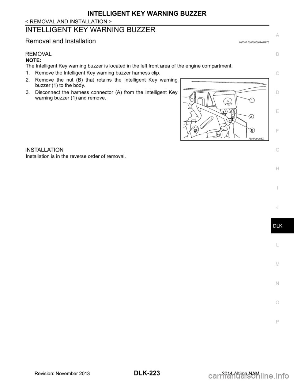
The Intelligent Key warning buzzer is located in the left front area of the engine compartment.
1. Remove the Intelligent Key warning buzzer harness clip.
2. Remove the nut (B) that retains the Intelligent Key warning buzzer (1) to the body.
3. Disconnect the harness connector (A) from the Intelligent Key warning buzzer (1) and remove.
INSTALLATION
Installation is in the reverse order of removal.
ALKIA2728ZZ
Revision: November 20132014 Altima NAMRevision: November 20132014 Altima NAM
Page 992 of 4801
DLK-224
< REMOVAL AND INSTALLATION >
REMOTE KEYLESS ENTRY RECEIVER
REMOTE KEYLESS ENTRY RECEIVER
Removal and InstallationINFOID:0000000009461976
REMOVAL
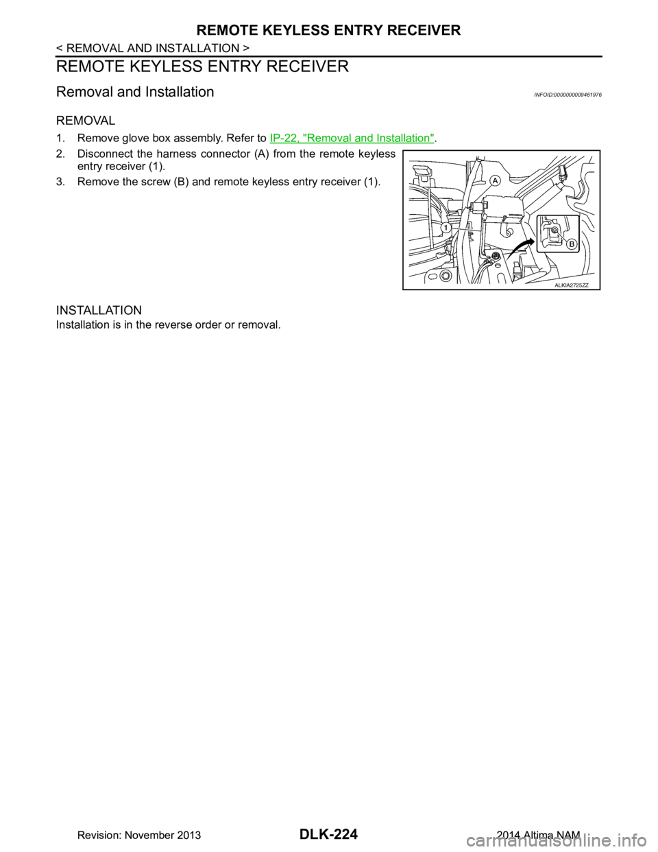
1. Remove glove box assembly. Refer to IP-22, "Removal and Installation".
2. Disconnect the harness connector (A) from the remote keyless entry receiver (1).
3. Remove the screw (B) and remote keyless entry receiver (1).
INSTALLATION
Installation is in the reverse order or removal.
ALKIA2725ZZ
Revision: November 20132014 Altima NAMRevision: November 20132014 Altima NAM
Page 993 of 4801
INTELLIGENT KEY BATTERYDLK-225
< REMOVAL AND INSTALLATION >
C
D E
F
G H
I
J
L
M A
B
DLK
N
O P
INTELLIGENT KEY BATTERY
Removal and InstallationINFOID:0000000009461977
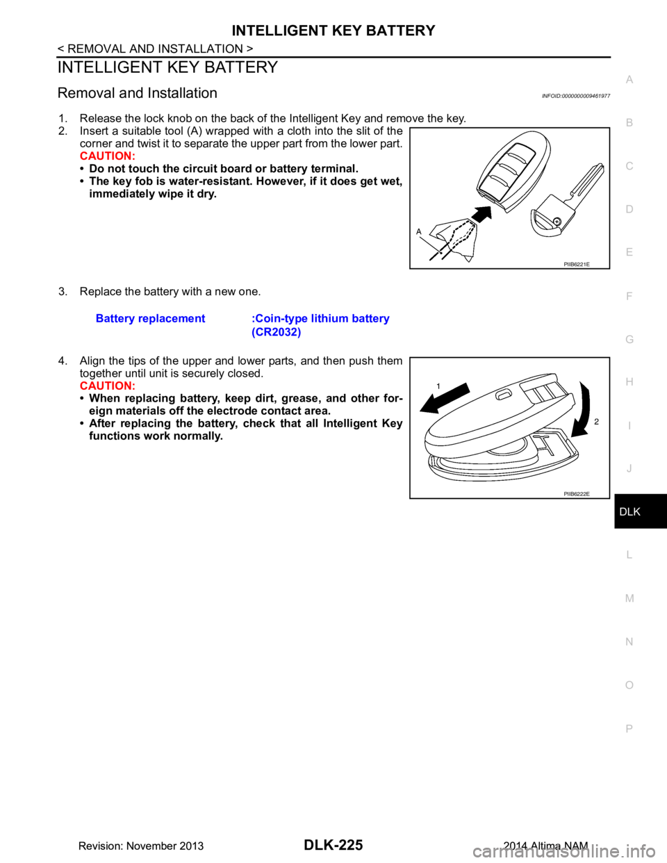
1. Release the lock knob on the back of the Intelligent Key and remove the key.
2. Insert a suitable tool (A) wrapped with a cloth into the slit of the corner and twist it to separate the upper part from the lower part.
CAUTION:
• Do not touch the circuit board or battery terminal.
• The key fob is water-resistant. However, if it does get wet,
immediately wipe it dry.
3. Replace the battery with a new one.
4. Align the tips of the upper and lower parts, and then push them together until unit is securely closed.
CAUTION:
• When replacing battery, keep dirt, grease, and other for-
eign materials off the electrode contact area.
• After replacing the battery, check that all Intelligent Key
functions work normally.
PIIB6221E
Battery replacement :Coin-type lithium battery
(CR2032)
PIIB6222E
Revision: November 20132014 Altima NAMRevision: November 20132014 Altima NAM
Page 994 of 4801
DLK-226
< REMOVAL AND INSTALLATION >
TRUNK LID OPENER CANCEL SWITCH
TRUNK LID OPENER CANCEL SWITCH
Removal and InstallationINFOID:0000000009461978
REMOVAL
1. Remove the glove box assembly. Refer to IP-22, "Removal and Installation".
2. Release pawls and remove the trunk cancel switch.
INSTALLATION
Installation is in the reverse order of removal.
Revision: November 20132014 Altima NAMRevision: November 20132014 Altima NAM
Page 995 of 4801
TRUNK LID OPENER SWITCHDLK-227
< REMOVAL AND INSTALLATION >
C
D E
F
G H
I
J
L
M A
B
DLK
N
O P
TRUNK LID OPENER SWITCH
Removal and InstallationINFOID:0000000009461979
REMOVAL
1. Remove the instrument lower panel LH. Refer to IP-21, "Removal and Installation".
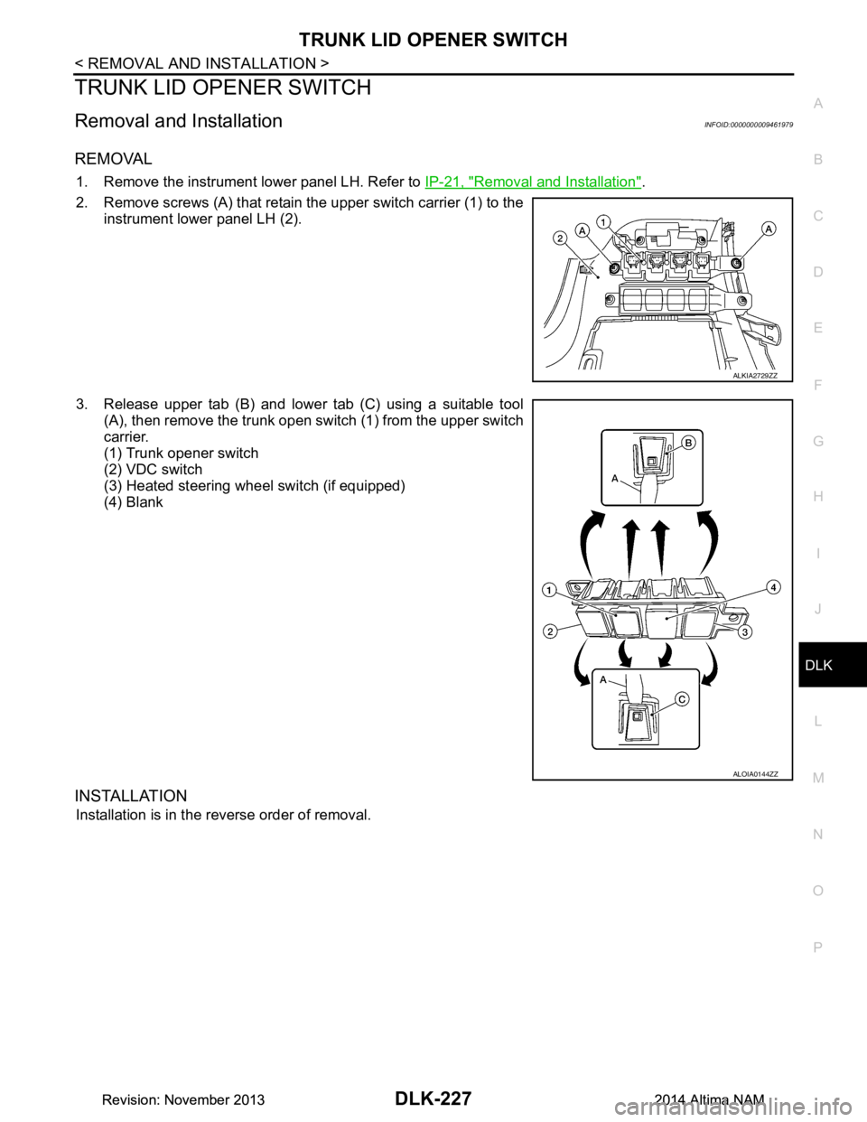
2. Remove screws (A) that retain the upper switch carrier (1) to the instrument lower panel LH (2).
3. Release upper tab (B) and lower tab (C) using a suitable tool (A), then remove the trunk open switch (1) from the upper switch
carrier.
(1) Trunk opener switch
(2) VDC switch
(3) Heated steering wheel switch (if equipped)
(4) Blank
INSTALLATION
Installation is in the reverse order of removal.
ALKIA2729ZZ
ALOIA0144ZZ
Revision: November 20132014 Altima NAMRevision: November 20132014 Altima NAM
Page 996 of 4801
DLK-228
< REMOVAL AND INSTALLATION >
TRUNK OPENER REQUEST SWITCH
TRUNK OPENER REQUEST SWITCH
Removal and InstallationINFOID:0000000009461980
REMOVAL
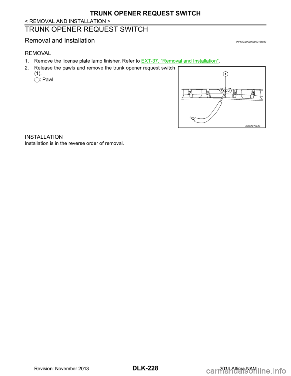
1. Remove the license plate lamp finisher. Refer to EXT-37, "Removal and Installation".
2. Release the pawls and remove the trunk opener request switch (1).
: Pawl
INSTALLATION
Installation is in the reverse order of removal.
ALKIA2722ZZ
Revision: November 20132014 Altima NAMRevision: November 20132014 Altima NAM
Page 997 of 4801
FRONT DOORDLK-229
< UNIT DISASSEMBLY AND ASSEMBLY >
C
D E
F
G H
I
J
L
M A
B
DLK
N
O P
UNIT DISASSEMBLY AND ASSEMBLY
FRONT DOOR
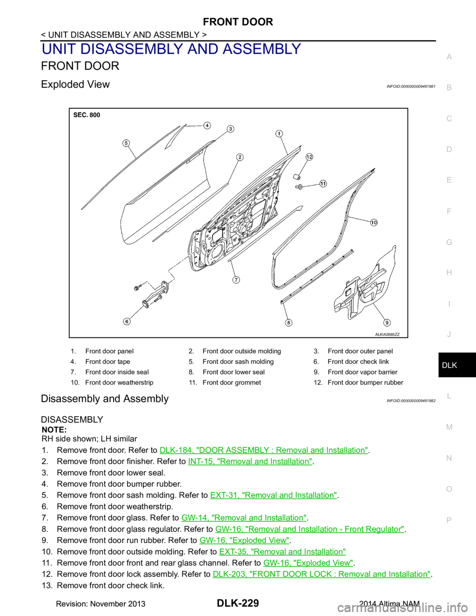
Exploded ViewINFOID:0000000009461981
Disassembly and AssemblyINFOID:0000000009461982
DISASSEMBLY
NOTE:
RH side shown; LH similar
1. Remove front door. Refer to DLK-184, "DOOR ASSEMBLY : Removal and Installation"
.
2. Remove front door finisher. Refer to INT-15, "Removal and Installation"
.
3. Remove front door lower seal.
4. Remove front door bumper rubber.
5. Remove front door sash molding. Refer to EXT-31, "Removal and Installation"
.
6. Remove front door weatherstrip.
7. Remove front door glass. Refer to GW-14, "Removal and Installation"
.
8. Remove front door glass regulator. Refer to GW-16, "Removal and Installation - Front Regulator"
.
9. Remove front door run rubber. Refer to GW-16, "Exploded View"
.
10. Remove front door outside molding. Refer to EXT-35, "Removal and Installation"
11. Remove front door front and rear glass channel. Refer to GW-16, "Exploded View".
12. Remove front door lock assembly. Refer to DLK-203, "FRONT DOOR LOCK : Removal and Installation"
.
13. Remove front door check link.
1. Front door panel 2. Front door outside molding 3. Front door outer panel
4. Front door tape 5. Front door sash molding 6. Front door check link
7. Front door inside seal 8. Front door lower seal 9. Front door vapor barrier
10. Front door weatherstrip 11. Front door grommet 12. Front door bumper rubber
ALKIA2685ZZ
Revision: November 20132014 Altima NAMRevision: November 20132014 Altima NAM
Page 998 of 4801
DLK-230
< UNIT DISASSEMBLY AND ASSEMBLY >
FRONT DOOR
ASSEMBLY
Assembly is in the reverse order of disassembly.
Revision: November 20132014 Altima NAMRevision: November 20132014 Altima NAM
Page 999 of 4801
REAR DOORDLK-231
< UNIT DISASSEMBLY AND ASSEMBLY >
C
D E
F
G H
I
J
L
M A
B
DLK
N
O P
REAR DOOR
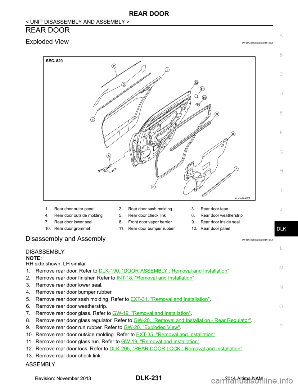
Exploded ViewINFOID:0000000009461983
Disassembly and AssemblyINFOID:0000000009461984
DISASSEMBLY
NOTE:
RH side shown; LH similar
1. Remove rear door. Refer to DLK-190, "DOOR ASSEMBLY : Removal and Installation"
.
2. Remove rear door finisher. Refer to INT-18, "Removal and Installation"
.
3. Remove rear door lower seal.
4. Remove rear door bumper rubber.
5. Remove rear door sash molding. Refer to EXT-31, "Removal and Installation"
.
6. Remove rear door weatherstrip.
7. Remove rear door glass. Refer to GW-19, "Removal and Installation"
.
8. Remove rear door glass regulator. Refer to GW-20, "Removal and Installation - Rear Regulator"
.
9. Remove rear door run rubber. Refer to GW-20, "Exploded View"
.
10. Remove rear door outside molding. Refer to EXT-35, "Removal and Installation"
.
11. Remove rear door glass run. Refer to GW-19, "Removal and Installation"
.
12. Remove rear door lock. Refer to DLK-205, "REAR DOOR LOCK : Removal and Installation"
.
13. Remove rear door check link.
ASSEMBLY
1. Rear door outer panel 2. Rear door sash molding 3. Rear door tape
4. Rear door outside molding 5. Rear door check link 6. Rear door weatherstrip
7. Rear door lower seal 8. Front door vapor barrier 9. Rear door inside seal
10. Rear door grommet 11. Rear door bumper rubber 12. Rear door panel
ALKIA2686ZZ
Revision: November 20132014 Altima NAMRevision: November 20132014 Altima NAM
Page 1000 of 4801
DLK-232
< UNIT DISASSEMBLY AND ASSEMBLY >
REAR DOOR
Assembly is in the reverse order of disassembly.
Revision: November 20132014 Altima NAMRevision: November 20132014 Altima NAM
Trending: fuse box, TPMS, wheel, boot, battery replacement, Crankshaft, engine oil
