NISSAN TEANA 2014 Service Manual
Manufacturer: NISSAN, Model Year: 2014, Model line: TEANA, Model: NISSAN TEANA 2014Pages: 4801, PDF Size: 51.2 MB
Page 971 of 4801
DOOR LOCKDLK-203
< REMOVAL AND INSTALLATION >
C
D E
F
G H
I
J
L
M A
B
DLK
N
O P
DOOR LOCK
FRONT DOOR LOCK
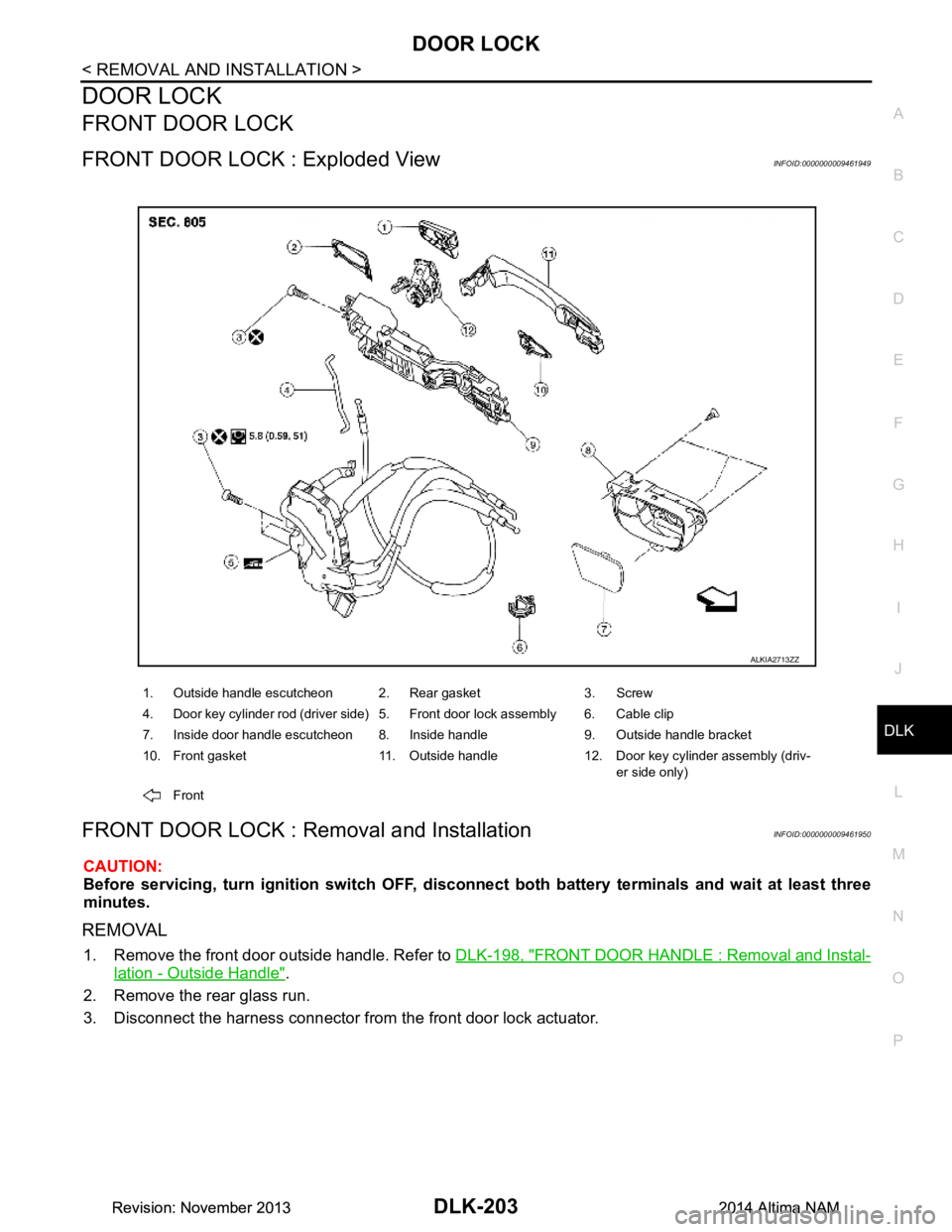
FRONT DOOR LOCK : Exploded ViewINFOID:0000000009461949
FRONT DOOR LOCK : Removal and InstallationINFOID:0000000009461950
CAUTION:
Before servicing, turn igni tion switch OFF, disconnect both batt ery terminals and wait at least three
minutes.
REMOVAL
1. Remove the front door outside handle. Refer to DLK-198, "FRONT DOOR HANDLE : Removal and Instal-
lation - Outside Handle".
2. Remove the rear glass run.
3. Disconnect the harness connector from the front door lock actuator.
1. Outside handle escutcheon 2. Rear gasket 3. Screw
4. Door key cylinder rod (driver side) 5. Front door lock assembly 6. Cable clip
7. Inside door handle escutcheon 8. Inside handle 9. Outside handle bracket
10. Front gasket 11. Outside handle 12. Door key cylinder assembly (driv- er side only)
Front
ALKIA2713ZZ
Revision: November 20132014 Altima NAMRevision: November 20132014 Altima NAM
Page 972 of 4801
DLK-204
< REMOVAL AND INSTALLATION >
DOOR LOCK
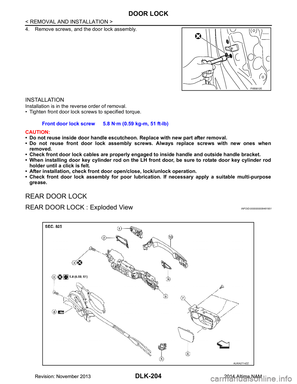
4. Remove screws, and the door lock assembly.
INSTALLATION
Installation is in the reverse order of removal.
• Tighten front door lock screws to specified torque.
CAUTION:
• Do not reuse inside door handle escutcheon. Replace with new part after removal.
• Do not reuse front door lock assembly screw s. Always replace screws with new ones when
removed.
• Check front door lock cables are properly engage d to inside handle and outside handle bracket.
• When installing door key cylinder rod on the LH front door, be sure to rotate door key cylinder rod
holder until a click is felt.
• After installation, check front doo r open/close, lock/unlock operation.
• Check front door lock assembly for poor lubricatio n. If necessary apply a suitable multi-purpose
grease.
REAR DOOR LOCK
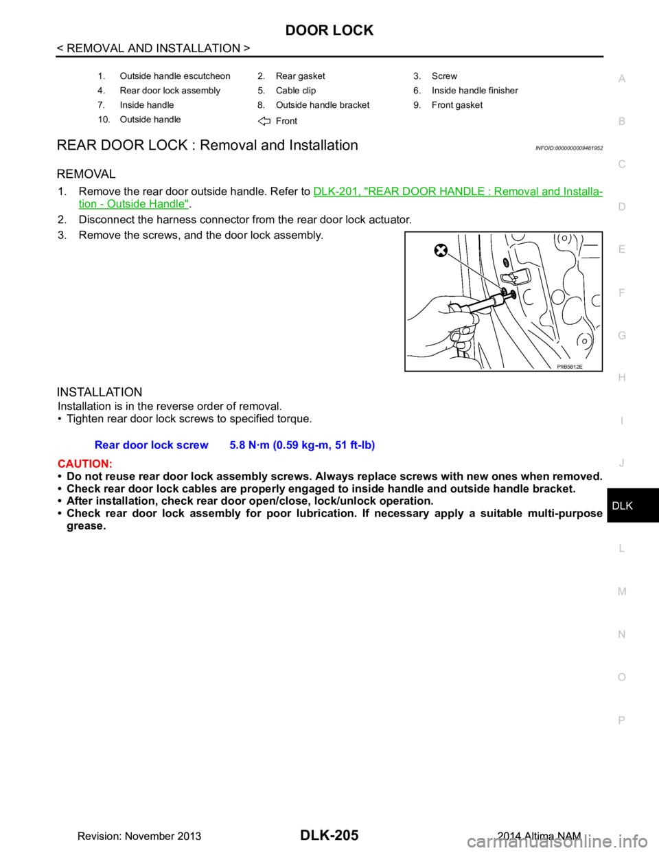
REAR DOOR LOCK : Exploded ViewINFOID:0000000009461951
PIIB5812E
Front door lock screw 5.8 N·m (0.59 kg-m, 51 ft-lb)
ALKIA2714ZZ
Revision: November 20132014 Altima NAMRevision: November 20132014 Altima NAM
Page 973 of 4801
DOOR LOCKDLK-205
< REMOVAL AND INSTALLATION >
C
D E
F
G H
I
J
L
M A
B
DLK
N
O P
REAR DOOR LOCK : Re moval and InstallationINFOID:0000000009461952
REMOVAL
1. Remove the rear door outside handle. Refer to DLK-201, "REAR DOOR HANDLE : Removal and Installa-
tion - Outside Handle".
2. Disconnect the harness connector from the rear door lock actuator.
3. Remove the screws, and the door lock assembly.
INSTALLATION
Installation is in the reverse order of removal.
• Tighten rear door lock screws to specified torque.
CAUTION:
• Do not reuse rear door lock assembly screws. Always replace screws with new ones when removed.
• Check rear door lock cables are properly engage d to inside handle and outside handle bracket.
• After installation, check rear doo r open/close, lock/unlock operation.
• Check rear door lock assembly for poor lubrication. If necessary apply a suitable multi-purpose
grease.
1. Outside handle escutcheon 2. Rear gasket 3. Screw
4. Rear door lock assembly 5. Cable clip 6. Inside handle finisher
7. Inside handle 8. Outside handle bracket 9. Front gasket
10. Outside handle Front
PIIB5812E
Rear door lock screw 5.8 N·m (0.59 kg-m, 51 ft-lb)
Revision: November 20132014 Altima NAMRevision: November 20132014 Altima NAM
Page 974 of 4801
DLK-206
< REMOVAL AND INSTALLATION >
TRUNK LID
TRUNK LID
TRUNK LID ASSEMBLY
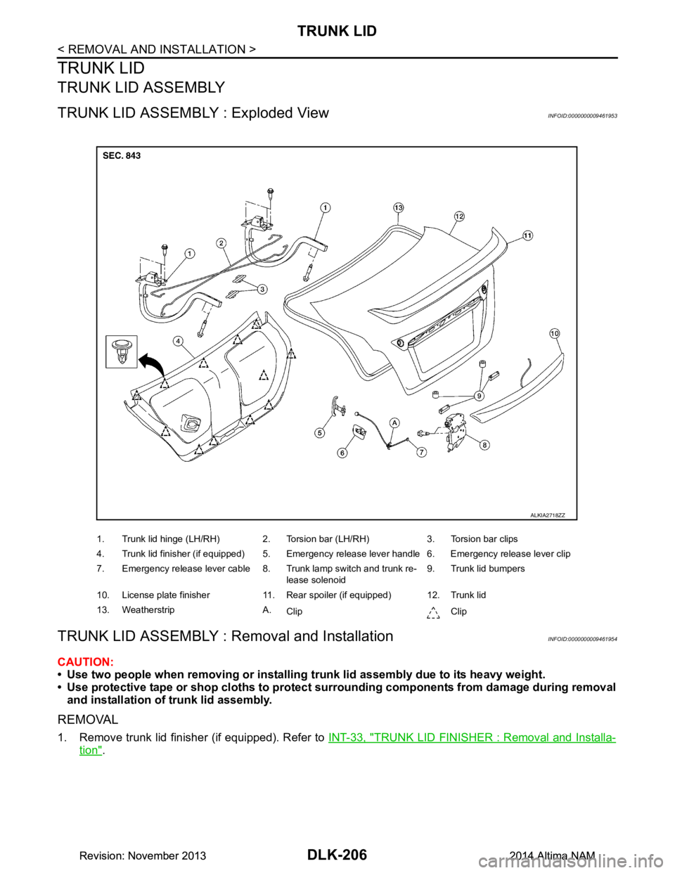
TRUNK LID ASSEMBLY : Exploded ViewINFOID:0000000009461953
TRUNK LID ASSEMBLY : Removal and InstallationINFOID:0000000009461954
CAUTION:
• Use two people when removing or installing trunk lid assembly due to its heavy weight.
• Use protective tape or shop cloths to protect surrounding components from damage during removal
and installation of trunk lid assembly.
REMOVAL
1. Remove trunk lid finisher (if equipped). Refer to INT-33, "TRUNK LID FINISHER : Removal and Installa-
tion".
1. Trunk lid hinge (LH/RH) 2. Torsion bar (LH/RH) 3. Torsion bar clips
4. Trunk lid finisher (if equipped) 5. Emergency release lever handle 6. Emergency release lever clip
7. Emergency release lever cable 8. Trunk lamp switch and trunk re- lease solenoid9. Trunk lid bumpers
10. License plate finisher 11. Rear spoiler (if equipped) 12. Trunk lid
13. Weatherstrip A. Clip Clip
ALKIA2718ZZ
Revision: November 20132014 Altima NAMRevision: November 20132014 Altima NAM
Page 975 of 4801
TRUNK LIDDLK-207
< REMOVAL AND INSTALLATION >
C
D E
F
G H
I
J
L
M A
B
DLK
N
O P
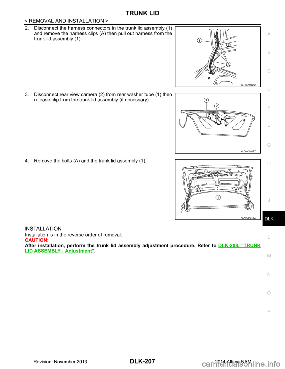
2. Disconnect the harness connectors in the trunk lid assembly (1) and remove the harness clips (A) then pull out harness from the
trunk lid assembly (1).
3. Disconnect rear view camera (2) from rear washer tube (1) then release clip from the truck lid assembly (if necessary).
4. Remove the bolts (A) and the trunk lid assembly (1).
INSTALLATION
Installation is in the reverse order of removal.
CAUTION:
After installation, perform the trunk lid assembly adjustment procedure. Refer to DLK-208, "TRUNK
LID ASSEMBLY : Adjustment".
ALKIA2733ZZ
ALOIA0202ZZ
ALKIA2734ZZ
Revision: November 20132014 Altima NAMRevision: November 20132014 Altima NAM
Page 976 of 4801
DLK-208
< REMOVAL AND INSTALLATION >
TRUNK LID
TRUNK LID ASSEMBLY : Adjustment
INFOID:0000000009461955
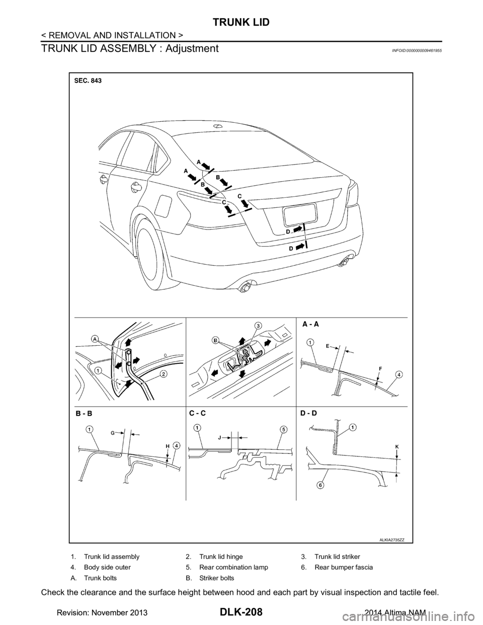
Check the clearance and the surface height between hood and each part by visual inspection and tactile feel.
1. Trunk lid assembly 2. Trunk lid hinge 3. Trunk lid striker
4. Body side outer 5. Rear combination lamp 6. Rear bumper fascia
A. Trunk bolts B. Striker bolts
ALKIA2735ZZ
Revision: November 20132014 Altima NAMRevision: November 20132014 Altima NAM
Page 977 of 4801
TRUNK LIDDLK-209
< REMOVAL AND INSTALLATION >
C
D E
F
G H
I
J
L
M A
B
DLK
N
O P
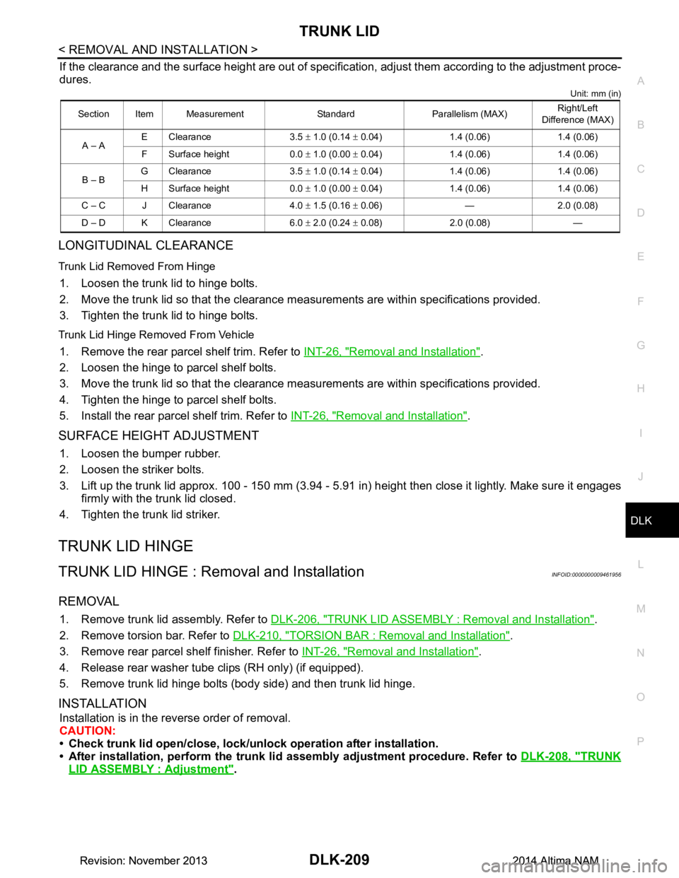
If the clearance and the surface height are out of specific ation, adjust them according to the adjustment proce-
dures.
Unit: mm (in)
LONGITUDINAL CLEARANCE
Trunk Lid Removed From Hinge
1. Loosen the trunk lid to hinge bolts.
2. Move the trunk lid so that the clearance m easurements are within specifications provided.
3. Tighten the trunk lid to hinge bolts.
Trunk Lid Hinge Removed From Vehicle
1. Remove the rear parcel shelf trim. Refer to INT-26, "Removal and Installation".
2. Loosen the hinge to parcel shelf bolts.
3. Move the trunk lid so that the clearance m easurements are within specifications provided.
4. Tighten the hinge to parcel shelf bolts.
5. Install the rear parcel shelf trim. Refer to INT-26, "Removal and Installation"
.
SURFACE HEIGHT ADJUSTMENT
1. Loosen the bumper rubber.
2. Loosen the striker bolts.
3. Lift up the trunk lid approx. 100 - 150 mm (3.94 - 5.91 in) height then close it lightly. Make sure it engages
firmly with the trunk lid closed.
4. Tighten the trunk lid striker.
TRUNK LID HINGE
TRUNK LID HINGE : Remo val and InstallationINFOID:0000000009461956
REMOVAL
1. Remove trunk lid assembly. Refer to DLK-206, "TRUNK LID ASSEMBLY : Removal and Installation".
2. Remove torsion bar. Refer to DLK-210, "TORSION BAR : Removal and Installation"
.
3. Remove rear parcel shelf finisher. Refer to INT-26, "Removal and Installation"
.
4. Release rear washer tube clips (RH only) (if equipped).
5. Remove trunk lid hinge bolts (body side) and then trunk lid hinge.
INSTALLATION
Installation is in the reverse order of removal.
CAUTION:
• Check trunk lid open/close, lock/un lock operation after installation.
• After installation, perform the trunk li d assembly adjustment procedure. Refer to DLK-208, "TRUNK
LID ASSEMBLY : Adjustment".
Section Item Measurement Standard Parallelism (MAX) Right/Left
Difference (MAX)
A – A E Clearance 3.5
± 1.0 (0.14 ± 0.04) 1.4 (0.06) 1.4 (0.06)
F Surface height 0.0 ± 1.0 (0.00 ± 0.04) 1.4 (0.06) 1.4 (0.06)
B – B G Clearance 3.5
± 1.0 (0.14 ± 0.04) 1.4 (0.06) 1.4 (0.06)
H Surface height 0.0 ± 1.0 (0.00 ± 0.04) 1.4 (0.06) 1.4 (0.06)
C – C J Clearance 4.0 ± 1.5 (0.16 ± 0.06) — 2.0 (0.08)
D – D K Clearance 6.0 ± 2.0 (0.24 ± 0.08) 2.0 (0.08) —
Revision: November 20132014 Altima NAMRevision: November 20132014 Altima NAM
Page 978 of 4801
DLK-210
< REMOVAL AND INSTALLATION >
TRUNK LID
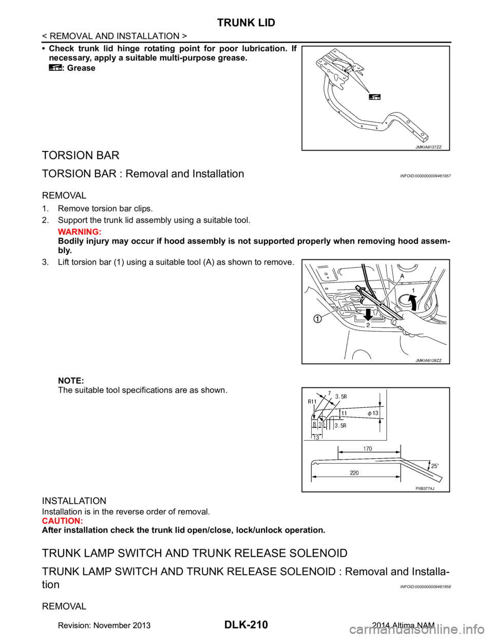
• Check trunk lid hinge rotating point for poor lubrication. If
necessary, apply a suitable multi-purpose grease.
: Grease
TORSION BAR
TORSION BAR : Remova l and InstallationINFOID:0000000009461957
REMOVAL
1. Remove torsion bar clips.
2. Support the trunk lid assembly using a suitable tool. WARNING:
Bodily injury may occur if hood assembly is not supported properly when removing hood assem-
bly.
3. Lift torsion bar (1) using a suitable tool (A) as shown to remove.
NOTE:
The suitable tool specifications are as shown.
INSTALLATION
Installation is in the reverse order of removal.
CAUTION:
After installation check the trunk li d open/close, lock/unlock operation.
TRUNK LAMP SWITCH AND TRUNK RELEASE SOLENOID
TRUNK LAMP SWITCH AND TRUNK RELEASE SOLENOID : Removal and Installa-
tion
INFOID:0000000009461958
REMOVAL
JMKIA8127ZZ
JMKIA8128ZZ
PIIB3774J
Revision: November 20132014 Altima NAMRevision: November 20132014 Altima NAM
Page 979 of 4801
TRUNK LIDDLK-211
< REMOVAL AND INSTALLATION >
C
D E
F
G H
I
J
L
M A
B
DLK
N
O P
1. Remove the trunk lid finisher (if equipped). Refer to INT-33, "TRUNK LID FINISHER : Removal and Instal-
lation".
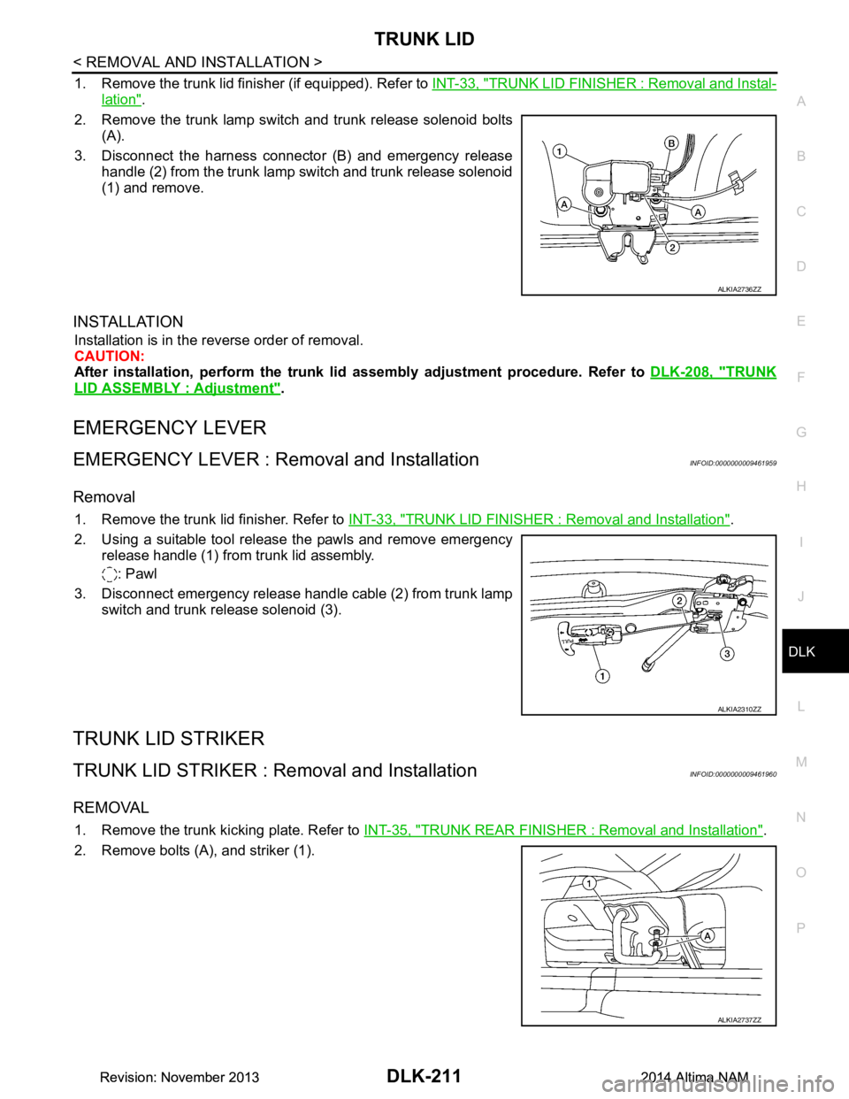
2. Remove the trunk lamp switch and trunk release solenoid bolts (A).
3. Disconnect the harness connector (B) and emergency release handle (2) from the trunk lamp switch and trunk release solenoid
(1) and remove.
INSTALLATION
Installation is in the reverse order of removal.
CAUTION:
After installation, perform the trunk lid assembly adjustment procedure. Refer to DLK-208, "TRUNK
LID ASSEMBLY : Adjustment".
EMERGENCY LEVER
EMERGENCY LEVER : Removal and InstallationINFOID:0000000009461959
Removal
1. Remove the trunk lid finisher. Refer to INT-33, "TRUNK LID FINISHER : Removal and Installation".
2. Using a suitable tool release the pawls and remove emergency release handle (1) from trunk lid assembly.
: Pawl
3. Disconnect emergency release handle cable (2) from trunk lamp switch and trunk release solenoid (3).
TRUNK LID STRIKER
TRUNK LID STRIKER : Re moval and InstallationINFOID:0000000009461960
REMOVAL
1. Remove the trunk kicking plate. Refer to INT-35, "TRUNK REAR FINISHER : Removal and Installation".
2. Remove bolts (A), and striker (1).
ALKIA2736ZZ
ALKIA2310ZZ
ALKIA2737ZZ
Revision: November 20132014 Altima NAMRevision: November 20132014 Altima NAM
Page 980 of 4801

DLK-212
< REMOVAL AND INSTALLATION >
TRUNK LID
INSTALLATION
Installation is in the reverse order of removal.
CAUTION:
After installation, perform the trunk lid assembly adjustment procedure. Refer to DLK-208, "TRUNK
LID ASSEMBLY : Adjustment".
Revision: November 20132014 Altima NAMRevision: November 20132014 Altima NAM