stall speed NISSAN TEANA 2014 Service Manual
[x] Cancel search | Manufacturer: NISSAN, Model Year: 2014, Model line: TEANA, Model: NISSAN TEANA 2014Pages: 4801, PDF Size: 51.2 MB
Page 4589 of 4801
![NISSAN TEANA 2014 Service Manual
TM-374
< SYMPTOM DIAGNOSIS >[CVT: RE0F10E]
CVT CONTROL SYSTEM
OtherNo creep at all. 243789101112 5613141
Vehicle cannot run in any position. 8 256791011 3412131
With selector lever in D position,](/img/5/57390/w960_57390-4588.png "NISSAN TEANA 2014 Service Manual
TM-374
< SYMPTOM DIAGNOSIS >[CVT: RE0F10E]
CVT CONTROL SYSTEM
OtherNo creep at all. 243789101112 5613141
Vehicle cannot run in any position. 8 256791011 3412131
With selector lever in D position,")
TM-374
< SYMPTOM DIAGNOSIS >[CVT: RE0F10E]
CVT CONTROL SYSTEM
OtherNo creep at all. 243789101112 5613141
Vehicle cannot run in any position. 8 256791011 3412131
With selector lever in D position,
driving is not possible. 8 256791011 3412131
With selector lever in R position,
driving is not possible. 8 256791011 3412131
Judder occurs during lock-up. 2 6 3 4 5 7 8 1
Strange noise in D position. 2 3 4 1
Strange noise in R position. 2 3 4 1
Strange noise in N position. 2 3 4 1
Vehicle does not decelerate by en-
gine brake. 73 456 2 81
Maximum speed low. 23 567 89114 101
With selector lever in P position, ve-
hicle does not enter parking condi-
tion or, with selector lever in another
position, parking condition is not
cancelled. 12
Vehicle runs with CVT in P position. 1 3 4 2
Vehicle runs with CVT in N position. 1 3 4 2
Engine stall. 26 34 8957 101
Engine stalls when selector lever
shifted N → D or R. 26 34 5 71
Engine speed does not return to
idle. 24 3 51
Engine does not start in N or P posi-
tion. 321
Engine starts in positions other than
N or P. 321
Symptom
Engine system
CAN communication line (U1000)
Transmission range switch (P0705, P0706)
Input speed sensor (P0717)
Primary speed sensor (P0715)
Output speed sensor (P2765)
CVT fluid temperature sensor (P0711, P0712, P0713)
Primary pressure sensor (P084C, P084D)
Secondary pressure sensor (P0841, P0847, P0848)
Torque converter clutch solenoid valve (P0740, P0743, P0744)
Stall te st
CVT position
Power supply
Control valve
CVT fluid level and state
Ignition switch and starter
EC-630
TM-263
TM-288TM-289TM-366TM-387TM-286
PG-19
,
STR-6
Revision: November 20132014 Altima NAMRevision: November 20132014 Altima NAM
Page 4591 of 4801
![NISSAN TEANA 2014 Service Manual
TM-376
< SYMPTOM DIAGNOSIS >[CVT: RE0F10E]
CVT CONTROL SYSTEM
OtherNo creep at all. 1 6 2 4 5 3
Vehicle cannot run in all posi-
tions. 1 2453 6
With selector lever in D position,
driving is not p](/img/5/57390/w960_57390-4590.png "NISSAN TEANA 2014 Service Manual
TM-376
< SYMPTOM DIAGNOSIS >[CVT: RE0F10E]
CVT CONTROL SYSTEM
OtherNo creep at all. 1 6 2 4 5 3
Vehicle cannot run in all posi-
tions. 1 2453 6
With selector lever in D position,
driving is not p")
TM-376
< SYMPTOM DIAGNOSIS >[CVT: RE0F10E]
CVT CONTROL SYSTEM
OtherNo creep at all. 1 6 2 4 5 3
Vehicle cannot run in all posi-
tions. 1 2453 6
With selector lever in D position,
driving is not possible. 12435
With selector lever in R position,
driving is not possible. 12435
Judder occurs during lock-up. 1
Strange noise in D position. 1 2 4 3 5
Strange noise in R position. 1 2 4 3
Strange noise in N position. 1 2 3
Maximum speed low. 1 5 2 4 3
With selector lever in P position,
vehicle does not enter parking
condition or, with selector lever in
another position, parking condi-
tion is not cancelled. 1
Vehicle runs with CVT in P posi-
tion. 21
Vehicle runs with CVT in N posi-
tion. 231
Engine stall. 1
Engine stalls when selector lever
shifted N → D or R. 1
When brake pedal is depressed
with ignition switch ON, selector-
lever cannot be shifted from P po-
sition to other position. 123
When brake pedal is not de-
pressed with ignition switch ON,
selector lever can be shifted from
P position to other position. 123
Symptom
Torque converter
Transmission range switch
Oil pump
Forward clutch
Reverse brake
Planetary gear
Bearings
Parking mechanism
Stop lamp switch
Shift lock solenoid
CVT shift selector
TM-410
TM-407BR-13TM-369TM-378
Revision: November 20132014 Altima NAMRevision: November 20132014 Altima NAM
Page 4608 of 4801
![NISSAN TEANA 2014 Service Manual
INPUT SPEED SENSORTM-393
< REMOVAL AND INSTALLATION > [CVT: RE0F10E]
C
EF
G H
I
J
K L
M A
B
TM
N
O P
INPUT SPEED SENSOR
Exploded ViewINFOID:0000000009464347
Removal and InstallationINFOID:0000000009](/img/5/57390/w960_57390-4607.png "NISSAN TEANA 2014 Service Manual
INPUT SPEED SENSORTM-393
< REMOVAL AND INSTALLATION > [CVT: RE0F10E]
C
EF
G H
I
J
K L
M A
B
TM
N
O P
INPUT SPEED SENSOR
Exploded ViewINFOID:0000000009464347
Removal and InstallationINFOID:0000000009")
INPUT SPEED SENSORTM-393
< REMOVAL AND INSTALLATION > [CVT: RE0F10E]
C
EF
G H
I
J
K L
M A
B
TM
N
O P
INPUT SPEED SENSOR
Exploded ViewINFOID:0000000009464347
Removal and InstallationINFOID:0000000009464348
REMOVAL
1. Remove the battery tray. Refer to PG-74, "Removal and Installation (Battery Tray)".
2. Remove the starter motor. Refer to STR-23, "VQ35DE : Removal and Installation"
.
3. Disconnect the harness connector from the input speed sensor
(1).
4. Remove the input speed sensor bolt, then the input speed sen- sor (1).
5. Remove the O-ring (2) from the input speed sensor (1). CAUTION:
Do not reuse O-ring.
INSTALLATION
Installation is in the reverse order of removal.
CAUTION:
• Do not reuse O-ring.
• Apply Genuine NISSAN CVT Fluid NS-3 to the O-ring.
Inspection and AdjustmentINFOID:0000000009464349
INSPECTION AFTER INSTALLATION
Check for CVT fluid leakage. Refer to TM-377, "Inspection".
ADJUSTMENT AFTER INSTALLATION
Transaxle assembly Input speed sensor O-ring
: Always replace after every disassembly.
: N m (kg-m, in-lb)
: Apply CVT fluid
JSDIA3619GB
ALDIA0362ZZ
Revision: November 20132014 Altima NAMRevision: November 20132014 Altima NAM
Page 4609 of 4801
![NISSAN TEANA 2014 Service Manual
TM-394
< REMOVAL AND INSTALLATION >[CVT: RE0F10E]
INPUT SPEED SENSOR
Adjust the CVT fluid level. Refer to
TM-286, "Adjustment".
Revision: November 20132014 Altima NAMRevision: November 20132014 Alti](/img/5/57390/w960_57390-4608.png "NISSAN TEANA 2014 Service Manual
TM-394
< REMOVAL AND INSTALLATION >[CVT: RE0F10E]
INPUT SPEED SENSOR
Adjust the CVT fluid level. Refer to
TM-286, \"Adjustment\".
Revision: November 20132014 Altima NAMRevision: November 20132014 Alti")
TM-394
< REMOVAL AND INSTALLATION >[CVT: RE0F10E]
INPUT SPEED SENSOR
Adjust the CVT fluid level. Refer to
TM-286, "Adjustment".
Revision: November 20132014 Altima NAMRevision: November 20132014 Altima NAM
Page 4610 of 4801
![NISSAN TEANA 2014 Service Manual
PRIMARY SPEED SENSORTM-395
< REMOVAL AND INSTALLATION > [CVT: RE0F10E]
C
EF
G H
I
J
K L
M A
B
TM
N
O P
PRIMARY SPEED SENSOR
Exploded ViewINFOID:0000000009464350
Removal and InstallationINFOID:000000](/img/5/57390/w960_57390-4609.png "NISSAN TEANA 2014 Service Manual
PRIMARY SPEED SENSORTM-395
< REMOVAL AND INSTALLATION > [CVT: RE0F10E]
C
EF
G H
I
J
K L
M A
B
TM
N
O P
PRIMARY SPEED SENSOR
Exploded ViewINFOID:0000000009464350
Removal and InstallationINFOID:000000")
PRIMARY SPEED SENSORTM-395
< REMOVAL AND INSTALLATION > [CVT: RE0F10E]
C
EF
G H
I
J
K L
M A
B
TM
N
O P
PRIMARY SPEED SENSOR
Exploded ViewINFOID:0000000009464350
Removal and InstallationINFOID:0000000009464351
REMOVAL
1. Disconnect the negative battery terminal. Refer to PG-73, "Removal and Installation (Battery)".
2. Remove the fender protector side cover (LH). Refer to EXT-26, "FENDER PROTECTOR : Removal and
Installation".
3. Disconnect the harness connecto r from primary speed sensor
(1).
4. Remove the primary speed sensor bolt, then the primary speed sensor (1).
5. Remove the O-ring (2) from the primary speed sensor (1). CAUTION:
Do not reuse O-ring.
INSTALLATION
Installation is in the reverse order of removal.
CAUTION:
• Do not reuse O-ring.
• Apply Genuine NISSAN CVT Fluid NS-3 to the O-ring.
Inspection and AdjustmentINFOID:0000000009464352
INSPECTION AFTER INSTALLATION
Check for CVT fluid leakage. Refer to TM-377, "Inspection".
Transaxle assembly Primary speed sensor O-ring
: Always replace after every disassembly.
: N m (kg-m, in-lb)
: Apply CVT Fluid
JSDIA3620GB
ALDIA0361ZZ
Revision: November 20132014 Altima NAMRevision: November 20132014 Altima NAM
Page 4611 of 4801
![NISSAN TEANA 2014 Service Manual
TM-396
< REMOVAL AND INSTALLATION >[CVT: RE0F10E]
PRIMARY SPEED SENSOR
ADJUSTMENT AFTER INSTALLATION
Adjust the CVT fluid level. Refer to
TM-286, "Adjustment".
Revision: November 20132014 Altima NAM](/img/5/57390/w960_57390-4610.png "NISSAN TEANA 2014 Service Manual
TM-396
< REMOVAL AND INSTALLATION >[CVT: RE0F10E]
PRIMARY SPEED SENSOR
ADJUSTMENT AFTER INSTALLATION
Adjust the CVT fluid level. Refer to
TM-286, \"Adjustment\".
Revision: November 20132014 Altima NAM")
TM-396
< REMOVAL AND INSTALLATION >[CVT: RE0F10E]
PRIMARY SPEED SENSOR
ADJUSTMENT AFTER INSTALLATION
Adjust the CVT fluid level. Refer to
TM-286, "Adjustment".
Revision: November 20132014 Altima NAMRevision: November 20132014 Altima NAM
Page 4612 of 4801
![NISSAN TEANA 2014 Service Manual
OUTPUT SPEED SENSORTM-397
< REMOVAL AND INSTALLATION > [CVT: RE0F10E]
C
EF
G H
I
J
K L
M A
B
TM
N
O P
OUTPUT SPEED SENSOR
Exploded ViewINFOID:0000000009464353
Removal and InstallationINFOID:00000000](/img/5/57390/w960_57390-4611.png "NISSAN TEANA 2014 Service Manual
OUTPUT SPEED SENSORTM-397
< REMOVAL AND INSTALLATION > [CVT: RE0F10E]
C
EF
G H
I
J
K L
M A
B
TM
N
O P
OUTPUT SPEED SENSOR
Exploded ViewINFOID:0000000009464353
Removal and InstallationINFOID:00000000")
OUTPUT SPEED SENSORTM-397
< REMOVAL AND INSTALLATION > [CVT: RE0F10E]
C
EF
G H
I
J
K L
M A
B
TM
N
O P
OUTPUT SPEED SENSOR
Exploded ViewINFOID:0000000009464353
Removal and InstallationINFOID:0000000009464354
REMOVAL
1. Disconnect the battery negative terminal. Refer to PG-73, "Removal and Installation (Battery)".
2. Disconnect the harness connector fr om output speed sensor (1).
3. Remove the output speed sensor bolt, then the output speed sensor (1).
4. Remove the O-ring (2) from the output speed sensor (1). CAUTION:
Do not reuse O-ring.
INSTALLATION
Installation is in the reverse order of removal.
CAUTION:
• Do not reuse O-ring.
• Apply Genuine NISSAN CVT Fluid NS-3 to the O-ring.
Inspection and AdjustmentINFOID:0000000009464355
INSPECTION AFTER INSTALLATION
Check for CVT fluid leakage. Refer to TM-377, "Inspection".
ADJUSTMENT AFTER INSTALLATION
Adjust the CVT fluid level. Refer to TM-286, "Adjustment".
Transaxle assembly Output speed sensor O-ring
: Always replace after every disassembly.
: N·m (kg-m, in-lb)
: Apply CVT Fluid
JSDIA4209GB
ALDIA0363ZZ
Revision: November 20132014 Altima NAMRevision: November 20132014 Altima NAM
Page 4628 of 4801
![NISSAN TEANA 2014 Service Manual
SERVICE DATA AND SPECIFICATIONS (SDS)TM-413
< SERVICE DATA AND SPECIFICATIONS (SDS) [CVT: RE0F10E]
C
EF
G H
I
J
K L
M A
B
TM
N
O P
SERVICE DATA AND SPECIFICATIONS (SDS)
SERVICE DATA AND SPECIFICATI](/img/5/57390/w960_57390-4627.png "NISSAN TEANA 2014 Service Manual
SERVICE DATA AND SPECIFICATIONS (SDS)TM-413
< SERVICE DATA AND SPECIFICATIONS (SDS) [CVT: RE0F10E]
C
EF
G H
I
J
K L
M A
B
TM
N
O P
SERVICE DATA AND SPECIFICATIONS (SDS)
SERVICE DATA AND SPECIFICATI")
SERVICE DATA AND SPECIFICATIONS (SDS)TM-413
< SERVICE DATA AND SPECIFICATIONS (SDS) [CVT: RE0F10E]
C
EF
G H
I
J
K L
M A
B
TM
N
O P
SERVICE DATA AND SPECIFICATIONS (SDS)
SERVICE DATA AND SPECIFICATIONS (SDS)
General SpecificationINFOID:0000000009464379
*1: Refer to MA-11, "FOR USA AND CANADA : Fluids and Lubricants".
*2: The CVT fluid capacity is the reference value.
Shift CharacteristicsINFOID:0000000009464380
Unit: rpm
CAUTION:
Lock-up is engaged at the vehicle speed of approximately 18 km/h (12 MPH) to 40 km/h (24 MPH).
Stall SpeedINFOID:0000000009464381
Torque ConverterINFOID:0000000009464382
Unit: mm (in)
Heater ThermostatINFOID:0000000009464383
Standard
Reference value
Applied model Engine VQ35DE
Axle 2WD
Transaxle model RE0F10E
Transaxle gear ratio D position 2.436 – 0.384
R position 0.745
Final drive 4.677
Recommended fluid Genuine NISSAN CVT Fluid NS-3
*1
Fluid capacity liter (US qt, Imp qt) Approx. 8.2 (8-5/8, 7-1/4)*2
CAUTION:
• Use only Genuine NISSAN CVT Fluid NS-3. Never mix with other fluid.
• Using CVT fluid other than Genuine NISSAN CVT Fluid NS-3 will deteriorate in driveability and CVT durability, and may dam-
age the CVT, which is not covered by the NISSAN new vehicle limited warranty.
Throttle position Shift pattern Engine speed
At 40 km/h (25 MPH) At 60 km/h (37 MPH)
2/8 “D” position 1,410 – 1,550 1,550 – 1,710
8/8 “D” position 3,610 – 3,990 4,560 – 5,040
Stall speed 2,400 – 2,700 rpm
Distance “A” between the converter housing and torque converter 14.0 (0.55)
Va l v e l i f tMore than 5.0 mm (0.197 in)
Valve opening temperature 71 °C (160 °F)
Minimum valve lift 5.0 mm/85 °C (0.197 in/203 °F)
Revision: November 20132014 Altima NAMRevision: November 20132014 Altima NAM
Page 4651 of 4801
WCS
DIAGNOSIS SYSTEM (METER)WCS-9
< SYSTEM DESCRIPTION >
C
D E
F
G H
I
J
K L
M B
A
O P
DIAGNOSIS SYSTEM (METER)
DescriptionINFOID:0000000009941189
COMBINATION METER SE LF-DIAGNOSIS MODE
The following meter functions can be checked during Combination Meter Self-Diagnosis Mode:
• Pointer sweep of speedometer, tachometer and gauges.
• Illumination of all LCD segments and color patterns for meter displays.
• Illumination of all lamps/LEDs that are controlled by the combination meter (regardless of switch status).
STARTING COMBINATION METER SELF-DIAGNOSIS MODE
NOTE:
• Check combination meter power supply and ground circuits if self-diagnosis mode does not start. Refer to
MWI-58, "COMBINATION METER : Diagnosis Procedure"
. Replace combination meter if power supply and
ground circuits are found to be normal and self-diagnosis mode does not start. Refer to MWI-82, "Removal
and Installation".
• Combination meter self-diagnosis mode will function with the ignition switch in ON. Combination meter self-
diagnosis mode will exit upon turning the ignition switch to OFF.
How to Initiate Se lf-Diagnosis Mode
1. Press and hold the trip reset switch while turning the ignition switch ON. After 2 seconds release trip reset
switch, then press the trip reset switch 3 times withi n 7 seconds after the ignition switch is turned ON.
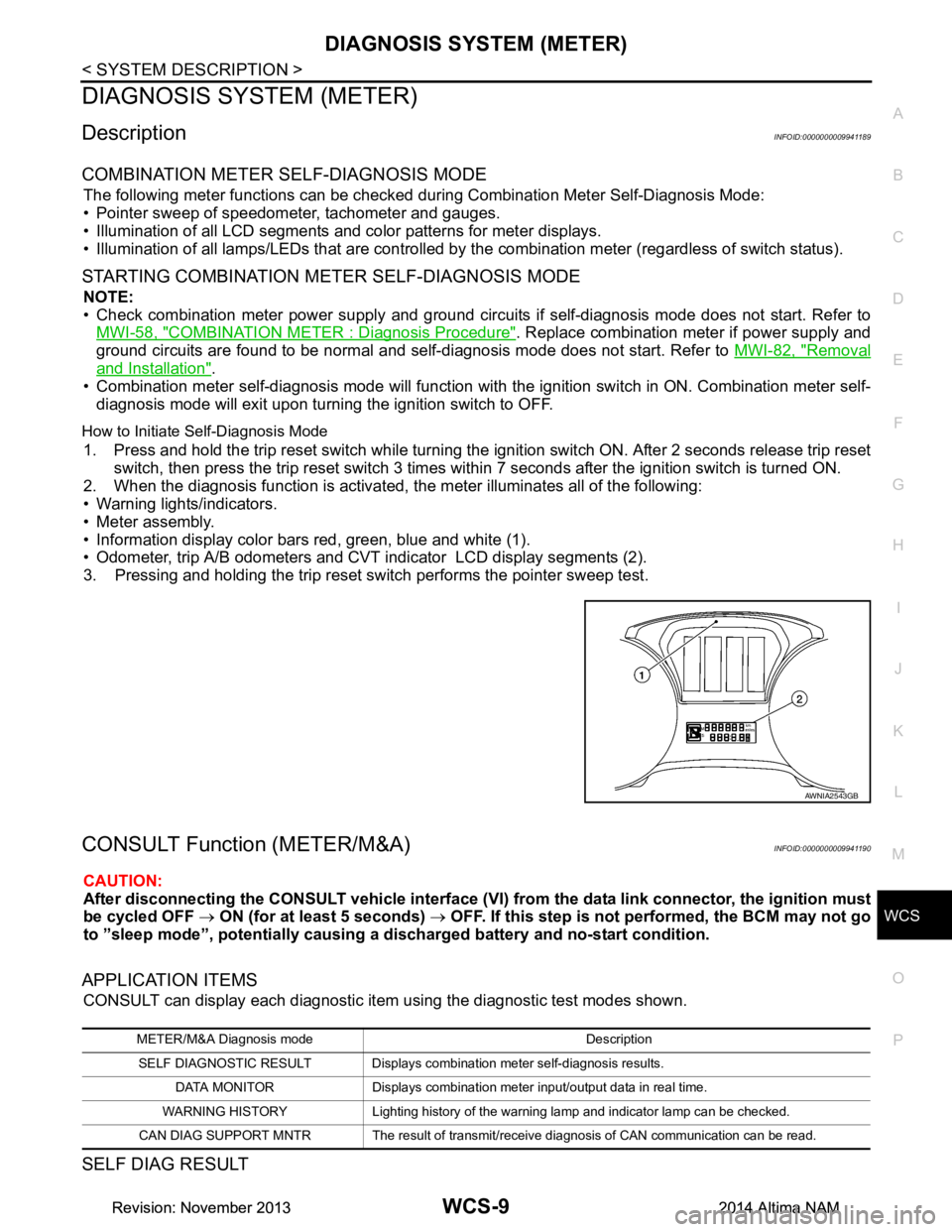
2. When the diagnosis function is activated, the meter illuminates all of the following:
• Warning lights/indicators.
• Meter assembly.
• Information display color bars red, green, blue and white (1).
• Odometer, trip A/B odometers and CVT indicator LCD display segments (2).
3. Pressing and holding the trip reset switch performs the pointer sweep test.
CONSULT Function (METER/M&A)INFOID:0000000009941190
CAUTION:
After disconnecting the CONSULT vehicle interface (VI) from the data link connector, the ignition must
be cycled OFF → ON (for at least 5 seconds) → OFF. If this step is not performed, the BCM may not go
to ”sleep mode”, potentiall y causing a discharged battery and no-start condition.
APPLICATION ITEMS
CONSULT can display each diagnostic item using the diagnostic test modes shown.
SELF DIAG RESULT
AWNIA2543GB
METER/M&A Diagnosis mode Description
SELF DIAGNOSTIC RESULT Displays combination meter self-diagnosis results. DATA MONITOR Displays combination meter input/output data in real time.
WARNING HISTORY Lighting history of the warning lamp and indicator lamp can be checked.
CAN DIAG SUPPORT MNTR The result of transmit/receive diagnosis of CAN communication can be read.
Revision: November 20132014 Altima NAMRevision: November 20132014 Altima NAM
Page 4677 of 4801

WT-2
C1720, C1721, C1722, C1723 TRANSMITTER ...
37
DTC Logic ............................................................ ...37
Diagnosis Procedure ..............................................37
C1724, C1725, C1726, C1727 TRANSMITTER
(BATT VOLT) .................................................. ...
39
DTC Logic ............................................................ ...39
Diagnosis Procedure ..............................................39
C1729 VEHICLE SPEED SIGNAL ....................41
DTC Logic ............................................................ ...41
Diagnosis Procedure ..............................................41
C1730, C1731, C1732, C1733 FLAT TIRE ........42
DTC Logic ............................................................ ...42
Diagnosis Procedure ..............................................42
C1734 BCM ........................................................44
DTC Logic ............................................................ ...44
Diagnosis Procedure ..............................................44
C1735 IGNITION SIGNAL .................................46
DTC Logic ............................................................ ...46
Diagnosis Procedure ..............................................46
SYMPTOM DIAGNOSIS .............................48
TPMS .............................................................. ...48
Symptom Table ................................................... ...48
LOW TIRE PRESSURE WARNING LAMP
DOES NOT TURN ON .................................... ...
49
Low Tire Pressure Warning Lamp Does Not Come
On When Ignition Switch Is Turned On ............... ...
49
LOW TIRE PRESSURE WARNING LAMP
STAYS ON ...................................................... ...
50
Low Tire Pressure Warning Lamp Stays On When
Ignition Switch Is Turned On ................................ ...
50
EASY FILL TIRE ALERT DOES NOT ACTI-
VATE ............................................................... ...
51
Description ........................................................... ...51
Diagnosis Procedure ...............................................51
NOISE, VIBRATION AND HARSHNESS
(NVH) TROUBLESHOOTING ......................... ...
52
NVH Troubleshooting Chart ....................................52
PERIODIC MAINTENANCE .......................53
ROAD WHEEL ................................................ ...53
Inspection ............................................................. ...53
REMOVAL AND INSTALLATION ..............54
REMOTE KEYLESS ENTRY RECEIVER ...... ...54
Removal and Installation .........................................54
ROAD WHEEL TIRE ASSEMBLY ................. ...55
Adjustment ........................................................... ...55
UNIT REMOVAL AND INSTALLATION ....57
TIRE PRESSURE SENSOR ........................... ...57
Exploded View ..................................................... ...57
Removal and Installation .........................................57
SERVICE DATA AND SPECIFICATIONS
(SDS) ............... ...........................................
60
SERVICE DATA AND SPECIFICATIONS
(SDS) .............................................................. ...
60
Road Wheel ......................................................... ...60
Tire ..........................................................................60
Revision: November 20132014 Altima NAMRevision: November 20132014 Altima NAM