timing NISSAN TEANA 2014 Service Manual
[x] Cancel search | Manufacturer: NISSAN, Model Year: 2014, Model line: TEANA, Model: NISSAN TEANA 2014Pages: 4801, PDF Size: 51.2 MB
Page 2012 of 4801
EM-14
< SYMPTOM DIAGNOSIS >[QR25DE]
NOISE, VIBRATION, AND HARSHNESS
(NVH) TROUBLESHOOTING
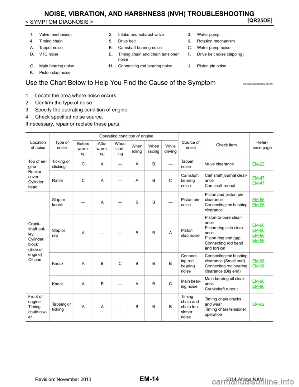
Use the Chart Below to Help You Find the Cause of the Symptom
INFOID:0000000009460464
1. Locate the area where noise occurs.
2. Confirm the type of noise.
3. Specify the operating condition of engine.
4. Check specified noise source.
If necessary, repair or replace these parts.
1. Valve mechanism 2. Intake and exhaust valve 3. Water pump
4. Timing chain 5. Drive belt 6. Rotation mechanism
A. Tappet noise B. Camshaft bearing noise C. Water pump noise
D. VTC noise E. Timing chain and chain tensioner noiseF. Drive belt noise (slipping)
G. Main bearing noise H. Connecting rod bearing noise J. Piston pin noise
K. Piston slap noise
Location of noise Typ e of
noise Operating condition of engine
Source of noise Check item
Refer-
ence page
Before
warm-
up After
warm-
up When
start-
ing When
idling When
racing While
driving
Top of en-
gine
Rocker
cover
Cylinder
head Ticking or
clicking CA—AB—
Tappet
noise Valve clearance
EM-23
Rattle C A — A B C Camshaft
bearing
noise Camshaft journal clear-
ance
Camshaft runout EM-47EM-47
Crank-
shaft pul-
ley
Cylinder
block
(Side of
engine)
Oil pan Slap or
knock —A—BB—
Piston pin
noise Piston and piston pin
clearance
Connecting rod bushing
clearance EM-96
EM-96
Slap or
rap A——BBA
Piston
slap noise Piston-to-bore clear-
ance
Piston ring side clear-
ance
Piston ring end gap
Connecting rod bend
and torsion EM-96EM-96
EM-96
EM-96
Knock A B C B B B
Connect-
ing rod
bearing
noise Connecting rod bushing
clearance (Small end)
Connecting rod bearing
clearance (Big end) EM-96EM-96
Knock A B — A B C
Main bear-
ing noise Main bearing oil clear-
ance
Crankshaft runout EM-96EM-96
Front of
engine
Timing
chain cov-
er Tapping or
ticking AA—BBB Timing
chain and
chain ten-
sioner
noise Timing chain cracks
and wear
Timing chain tensioner
operation EM-62
Revision: November 20132014 Altima NAM
Page 2021 of 4801
CAMSHAFT VALVE CLEARANCEEM-23
< PERIODIC MAINTENANCE > [QR25DE]
C
D E
F
G H
I
J
K L
M A
EM
NP
O
CAMSHAFT VALVE CLEARANCE
Camshaft valve clearanceINFOID:0000000009460474
• Perform this inspection as follows after removal, inst
allation, or replacement of the camshaft or any valve-
related parts, or if there are any unusual engine conditions due to changes in valve clearance over time
(starting, idling, and/or noise).
1. Remove the fender protector side cover (RH). Refer to EXT-26, "FENDER PROTECTOR : Removal and
Installation".
2. Remove the rocker cover using power tool. Refer to EM-45, "Removal and Installation"
.
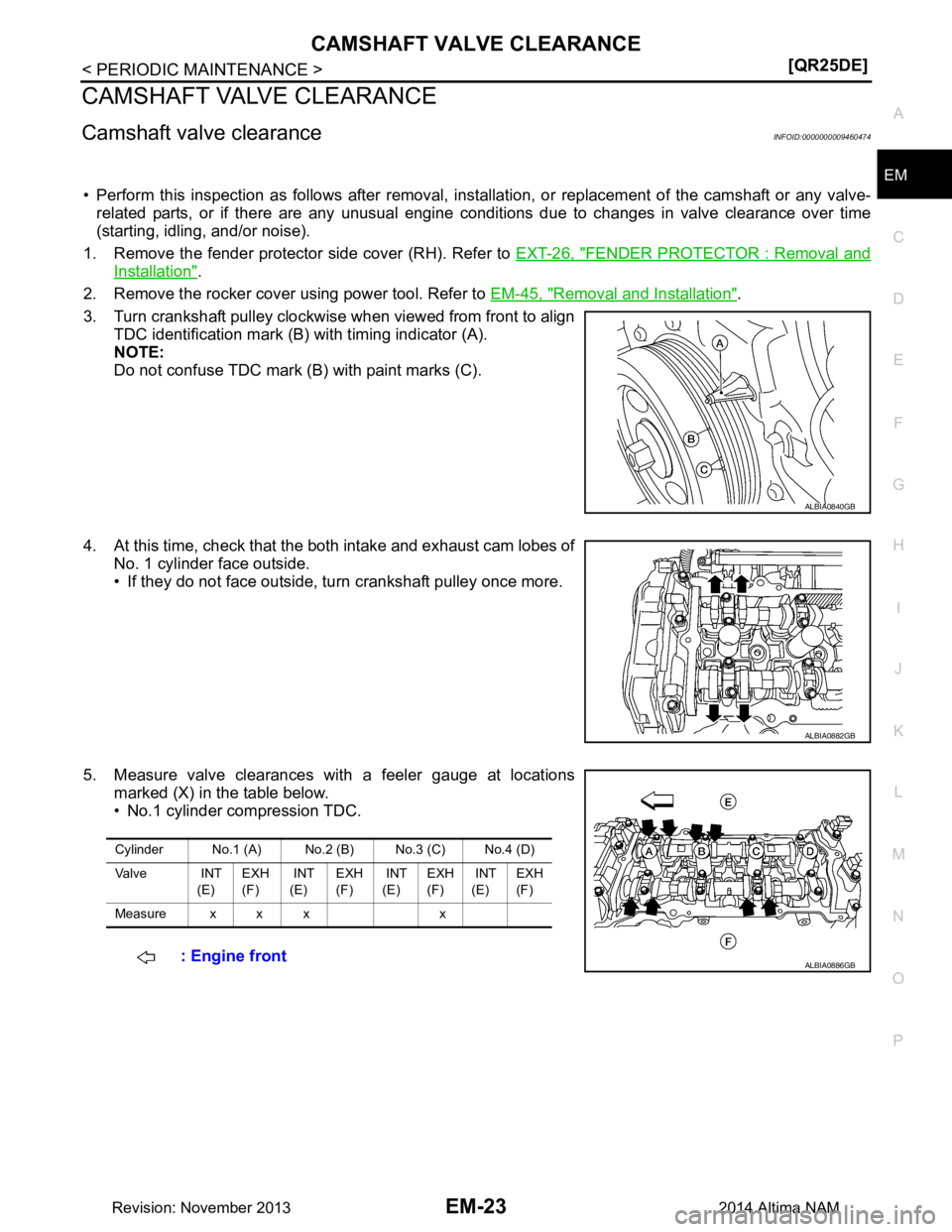
3. Turn crankshaft pulley clockwise when viewed from front to align TDC identification mark (B) with timing indicator (A).
NOTE:
Do not confuse TDC mark (B) with paint marks (C).
4. At this time, check that the both intake and exhaust cam lobes of No. 1 cylinder face outside.
• If they do not face outside, turn crankshaft pulley once more.
5. Measure valve clearances with a feeler gauge at locations marked (X) in the table below.
• No.1 cylinder compression TDC.
ALBIA0840GB
ALBIA0882GB
Cylinder No.1 (A) No.2 (B) No.3 (C) No.4 (D)
Va l v e I N T (E)EXH
(F) INT
(E) EXH
(F) INT
(E) EXH
(F) INT
(E) EXH
(F)
Measure x x x x
: Engine frontALBIA0886GB
Revision: November 20132014 Altima NAM
Page 2023 of 4801
CAMSHAFT VALVE CLEARANCEEM-25
< PERIODIC MAINTENANCE > [QR25DE]
C
D E
F
G H
I
J
K L
M A
EM
NP
O
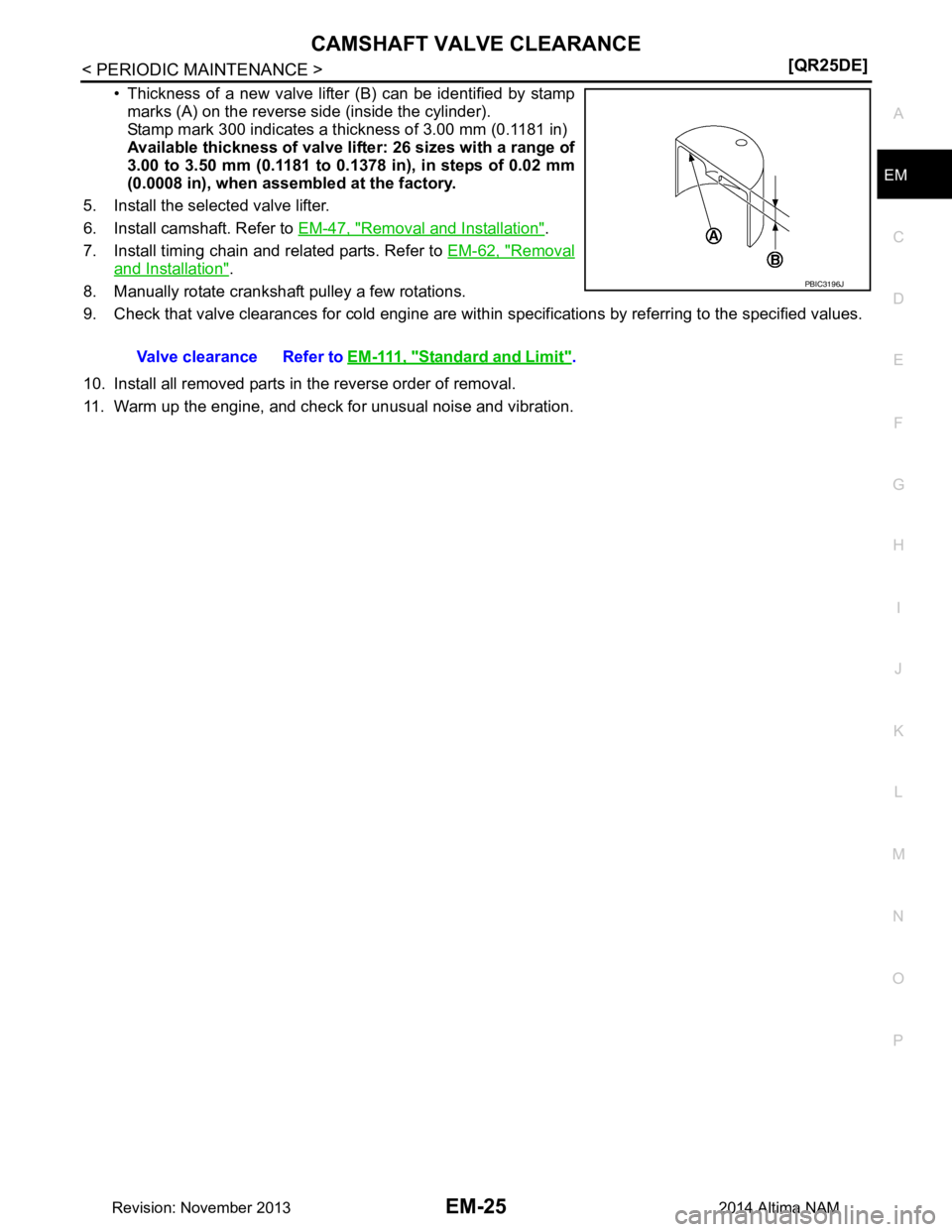
• Thickness of a new valve lifter (B) can be identified by stamp
marks (A) on the reverse side (inside the cylinder).
Stamp mark 300 indicates a thickness of 3.00 mm (0.1181 in)
Available thickness of valve lifter: 26 sizes with a range of
3.00 to 3.50 mm (0.1181 to 0.1378 in), in steps of 0.02 mm
(0.0008 in), when assembled at the factory.
5. Install the selected valve lifter.
6. Install camshaft. Refer to EM-47, "Removal and Installation"
.
7. Install timing chain and related parts. Refer to EM-62, "Removal
and Installation".
8. Manually rotate crankshaft pulley a few rotations.
9. Check that valve clearances for cold engine are within specifications by referring to the specified values.
10. Install all removed parts in the reverse order of removal.
11. Warm up the engine, and check for unusual noise and vibration. Valve clearance Refer to
EM-111, "Standard and Limit"
.
PBIC3196J
Revision: November 20132014 Altima NAM
Page 2045 of 4801
CAMSHAFTEM-47
< REMOVAL AND INSTALLATION > [QR25DE]
C
D E
F
G H
I
J
K L
M A
EM
NP
O
CAMSHAFT
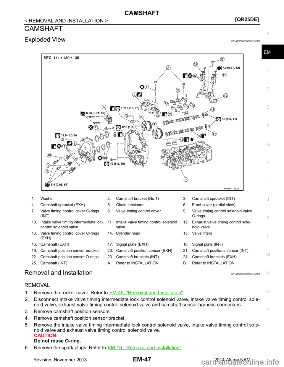
Exploded ViewINFOID:0000000009460492
Removal and InstallationINFOID:0000000009460493
REMOVAL
1. Remove the rocker cover. Refer to
EM-45, "Removal and Installation".
2. Disconnect intake valve timing intermediate lock contro l solenoid valve, intake valve timing control sole-
noid valve, exhaust valve timing control solenoi d valve and camshaft sensor harness connectors.
3. Remove camshaft position sensors.
4. Remove camshaft position sensor bracket.
5. Remove the intake valve timing intermediate lock control solenoid valve, intake valve timing control sole- noid valve and exhaust valve timing control solenoid valve.
CAUTION:
Do not reuse O-ring.
6. Remove the spark plugs. Refer to EM-16, "Removal and Installation"
.
1. Washer 2. Camshaft bracket (No.1) 3. Camshaft sprocket (INT)
4. Camshaft sprocket (EXH) 5. Chain tensioner 6. Front cover (partial view)
7. Valve timing control cover O-rings (INT) 8. Valve timing control cover 9. Valve timing control solenoid valve
O-rings
10. Intake valve timing intermediate lock control solenoid valve 11. Intake valve timing control solenoid
valve 12. Exhaust valve timing control sole-
noid valve
13. Valve timing control cover O-rings (EXH) 14. Cylinder head 15. Valve lifters
16. Camshaft (EXH) 17. Signal plate (EXH) 18. Signal plate (INT)
19. Camshaft position sensor bracket 20. Camshaft position sensor (EXH) 21. Camshaft positions sensor (INT)
22. Camshaft position sensor O-rings 23. Camshaft brackets (INT) 24. Camshaft brackets (EXH)
25. Camshaft (INT) A. Refer to INSTALLATION B. Refer to INSTALLATION
AWBIA1769ZZ
Revision: November 20132014 Altima NAM
Page 2046 of 4801
EM-48
< REMOVAL AND INSTALLATION >[QR25DE]
CAMSHAFT
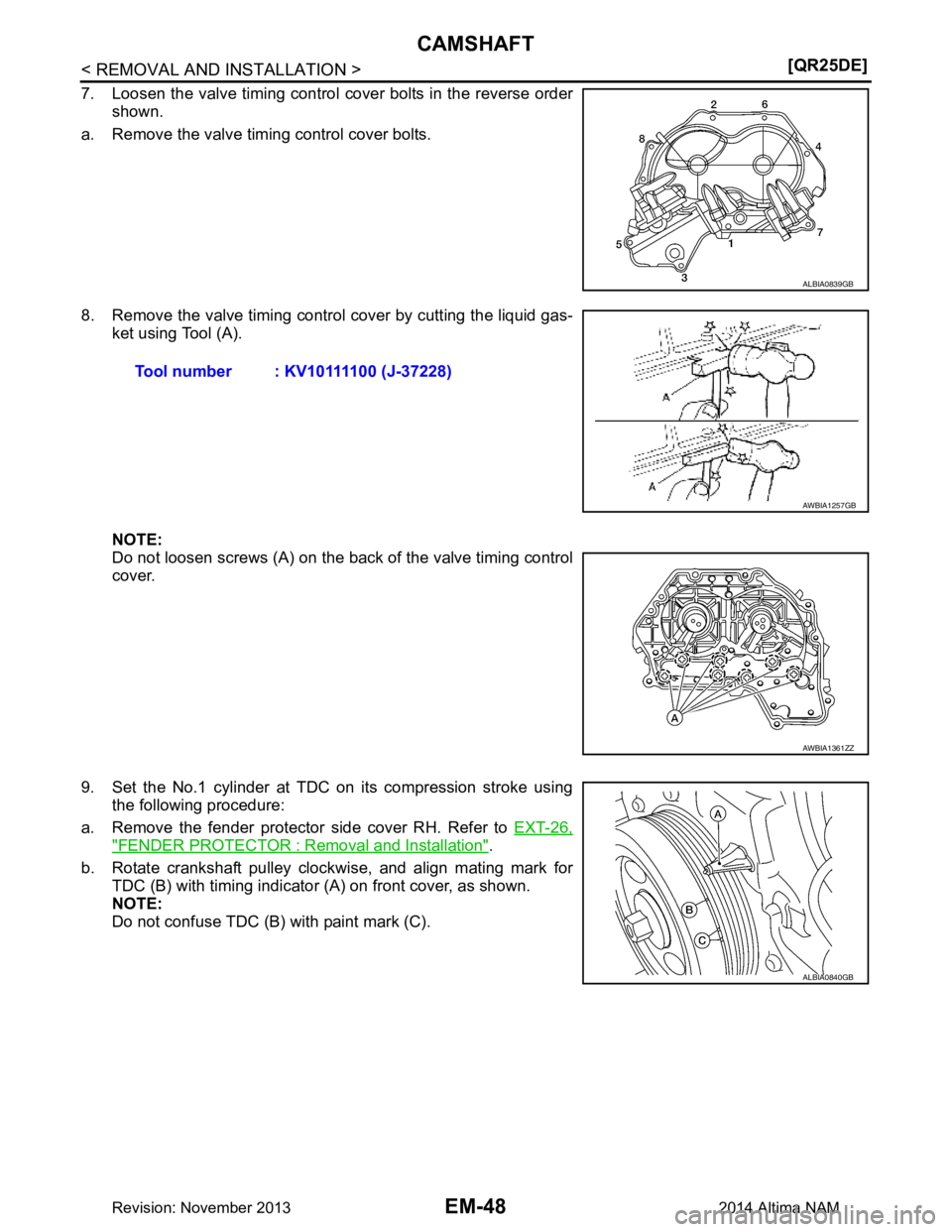
7. Loosen the valve timing control cover bolts in the reverse order
shown.
a. Remove the valve timing control cover bolts.
8. Remove the valve timing control cover by cutting the liquid gas- ket using Tool (A).
NOTE:
Do not loosen screws (A) on the back of the valve timing control
cover.
9. Set the No.1 cylinder at TDC on its compression stroke using the following procedure:
a. Remove the fender protector side cover RH. Refer to EXT-26,
"FENDER PROTECTOR : Removal and Installation".
b. Rotate crankshaft pulley clockwise, and align mating mark for TDC (B) with timing indicator (A) on front cover, as shown.
NOTE:
Do not confuse TDC (B) with paint mark (C).
ALBIA0839GB
Tool number : KV10111100 (J-37228)
AWBIA1257GB
AWBIA1361ZZ
ALBIA0840GB
Revision: November 20132014 Altima NAM
Page 2047 of 4801
CAMSHAFTEM-49
< REMOVAL AND INSTALLATION > [QR25DE]
C
D E
F
G H
I
J
K L
M A
EM
NP
O
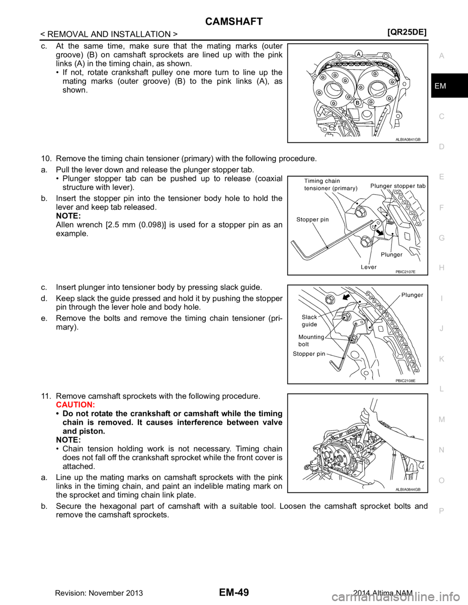
c. At the same time, make sure that the mating marks (outer
groove) (B) on camshaft sprockets are lined up with the pink
links (A) in the timing chain, as shown.
• If not, rotate crankshaft pulley one more turn to line up the
mating marks (outer groove) (B) to the pink links (A), as
shown.
10. Remove the timing chain tensioner (primary) with the following procedure.
a. Pull the lever down and release the plunger stopper tab. • Plunger stopper tab can be pushed up to release (coaxial
structure with lever).
b. Insert the stopper pin into the tensioner body hole to hold the lever and keep tab released.
NOTE:
Allen wrench [2.5 mm (0.098)] is used for a stopper pin as an
example.
c. Insert plunger into tensioner body by pressing slack guide.
d. Keep slack the guide pressed and hold it by pushing the stopper
pin through the lever hole and body hole.
e. Remove the bolts and remove the timing chain tensioner (pri- mary).
11. Remove camshaft sprockets with the following procedure. CAUTION:
• Do not rotate the crankshaft or camshaft while the timing chain is removed. It causes interference between valve
and piston.
NOTE:
• Chain tension holding work is not necessary. Timing chain does not fall off the crankshaft sprocket while the front cover is
attached.
a. Line up the mating marks on camshaft sprockets with the pink links in the timing chain, and paint an indelible mating mark on
the sprocket and timing chain link plate.
b. Secure the hexagonal part of camshaft with a suitable tool. Loosen the camshaft sprocket bolts and remove the camshaft sprockets.
ALBIA0841GB
PBIC2107E
PBIC2108E
ALBIA0844GB
Revision: November 20132014 Altima NAM
Page 2053 of 4801
CAMSHAFTEM-55
< REMOVAL AND INSTALLATION > [QR25DE]
C
D E
F
G H
I
J
K L
M A
EM
NP
O
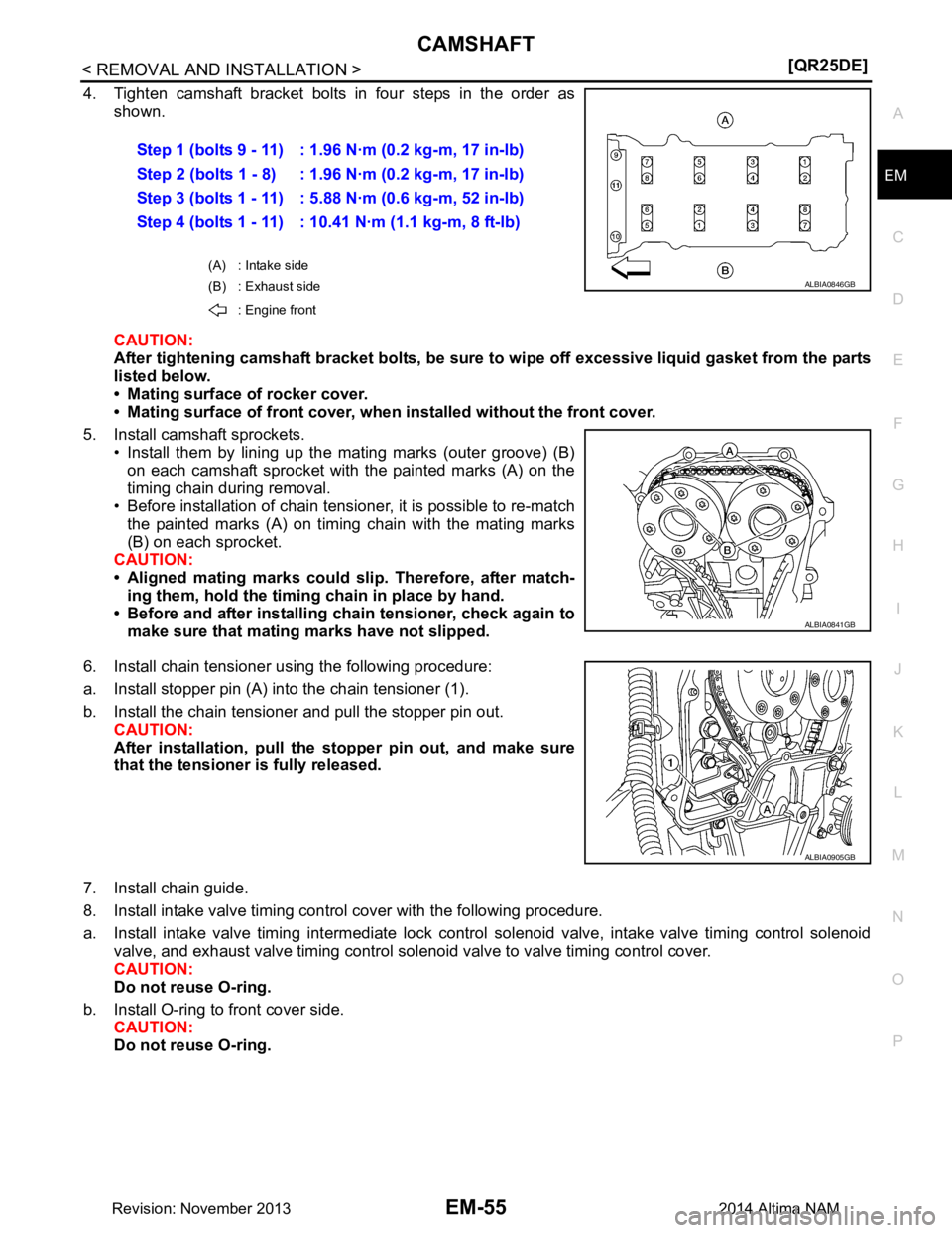
4. Tighten camshaft bracket bolts in four steps in the order as
shown.
CAUTION:
After tightening camshaft bracket bol ts, be sure to wipe off excessive liquid gasket from the parts
listed below.
• Mating surface of rocker cover.
• Mating surface of front cover, when installed without the front cover.
5. Install camshaft sprockets. • Install them by lining up the mating marks (outer groove) (B)
on each camshaft sprocket with the painted marks (A) on the
timing chain during removal.
• Before installation of chain tensioner, it is possible to re-match
the painted marks (A) on timing chain with the mating marks
(B) on each sprocket.
CAUTION:
• Aligned mating marks could slip. Therefore, after match-
ing them, hold the timing chain in place by hand.
• Before and after installing chain tensioner, check again to
make sure that mating marks have not slipped.
6. Install chain tensioner using the following procedure:
a. Install stopper pin (A) into the chain tensioner (1).
b. Install the chain tensioner and pull the stopper pin out. CAUTION:
After installation, pull the stopper pin out, and make sure
that the tensioner is fully released.
7. Install chain guide.
8. Install intake valve timing control cover with the following procedure.
a. Install intake valve timing intermediate lock control solenoid valve, intake valve timing control solenoid
valve, and exhaust valve timing control solenoid valve to valve timing control cover.
CAUTION:
Do not reuse O-ring.
b. Install O-ring to front cover side. CAUTION:
Do not reuse O-ring. Step 1 (bolts 9 - 11) : 1.96 N·m (0.2 kg-m, 17 in-lb)
Step 2 (bolts 1 - 8) : 1.96 N·m (0.2 kg-m, 17 in-lb)
Step 3 (bolts 1 - 11) : 5.88 N·m (0.6 kg-m, 52 in-lb)
Step 4 (bolts 1 - 11) : 10.41 N·m (1.1 kg-m, 8 ft-lb)
(A) : Intake side
(B) : Exhaust side
: Engine front
ALBIA0846GB
ALBIA0841GB
ALBIA0905GB
Revision: November 20132014 Altima NAM
Page 2054 of 4801
EM-56
< REMOVAL AND INSTALLATION >[QR25DE]
CAMSHAFT
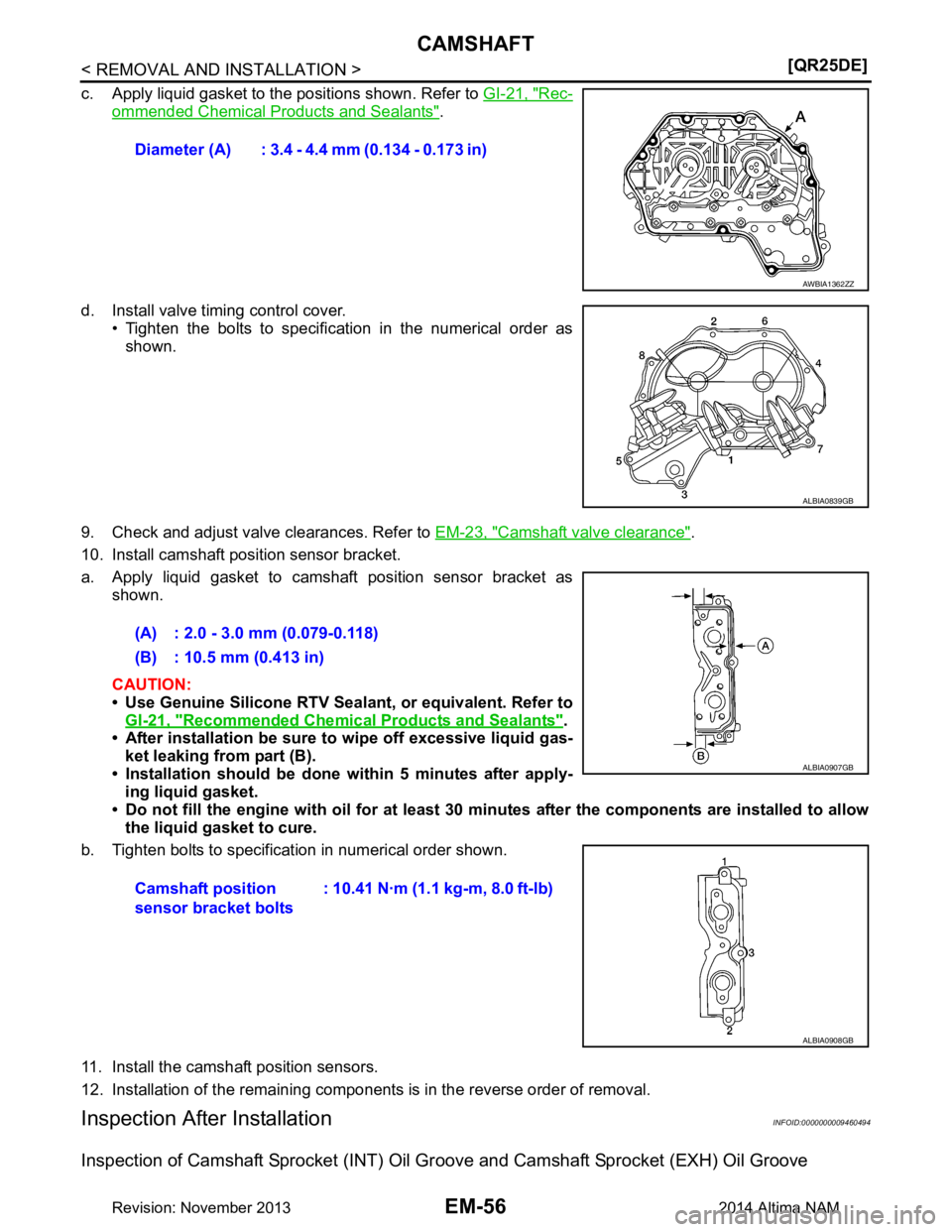
c. Apply liquid gasket to the positions shown. Refer to
GI-21, "Rec-
ommended Chemical Products and Sealants".
d. Install valve timing control cover. • Tighten the bolts to specification in the numerical order asshown.
9. Check and adjust valve clearances. Refer to EM-23, "Camshaft valve clearance"
.
10. Install camshaft position sensor bracket.
a. Apply liquid gasket to camshaft position sensor bracket as shown.
CAUTION:
• Use Genuine Silicone RTV Seal ant, or equivalent. Refer to
GI-21, "Recommended Chemical Products and Sealants"
.
• After installation be sure to wipe off excessive liquid gas-
ket leaking from part (B).
• Installation should be done within 5 minutes after apply-
ing liquid gasket.
• Do not fill the engine with oil for at least 30 minutes after the co mponents are installed to allow
the liquid gasket to cure.
b. Tighten bolts to specification in numerical order shown.
11. Install the camshaft position sensors.
12. Installation of the remaining components is in the reverse order of removal.
Inspection After InstallationINFOID:0000000009460494
Inspection of Camshaft Sprocket (INT) Oil Gr oove and Camshaft Sprocket (EXH) Oil Groove
Diameter (A) : 3.4 - 4.4 mm (0.134 - 0.173 in)
AWBIA1362ZZ
ALBIA0839GB
(A) : 2.0 - 3.0 mm (0.079-0.118)
(B) : 10.5 mm (0.413 in)
Camshaft position
sensor bracket bolts : 10.41 N·m (1.1 kg-m, 8.0 ft-lb)
ALBIA0907GB
ALBIA0908GB
Revision: November 20132014 Altima NAM
Page 2055 of 4801
CAMSHAFTEM-57
< REMOVAL AND INSTALLATION > [QR25DE]
C
D E
F
G H
I
J
K L
M A
EM
NP
O
WARNING:
Check when engine is cold so as to preven t burns from any splashing engine oil.
CAUTION:
Perform this inspection only when DTC P0011, P0014, P052A, P052B is detected in self-diagnostic
results of CONSULT and it is directed according to inspection procedure of EC section. Refer to EC-
210, "Diagnosis Procedure".
1. Check engine oil level and adjust oil level as necessary. Refer to LU-9, "Inspection"
.
2. Remove the intake valve timing intermediate lock control solenoid valve, intake valve timing control sole- noid valve, and exhaust valve timing control solenoid valve. Refer to EM-58, "Intake Valve Timing Interme-
diate Lock Control Solenoid Valve, Intake Valve Timing Control Solenoid Valve, and Exhaust Valve Timing
Control Solenoid Valve".
3. Perform the following procedure to prevent the engi ne from being unintentionally started while checking.
a. Release fuel pressure. Refer to EC-182, "Work Procedure"
.
b. Disconnect injector harness connectors.
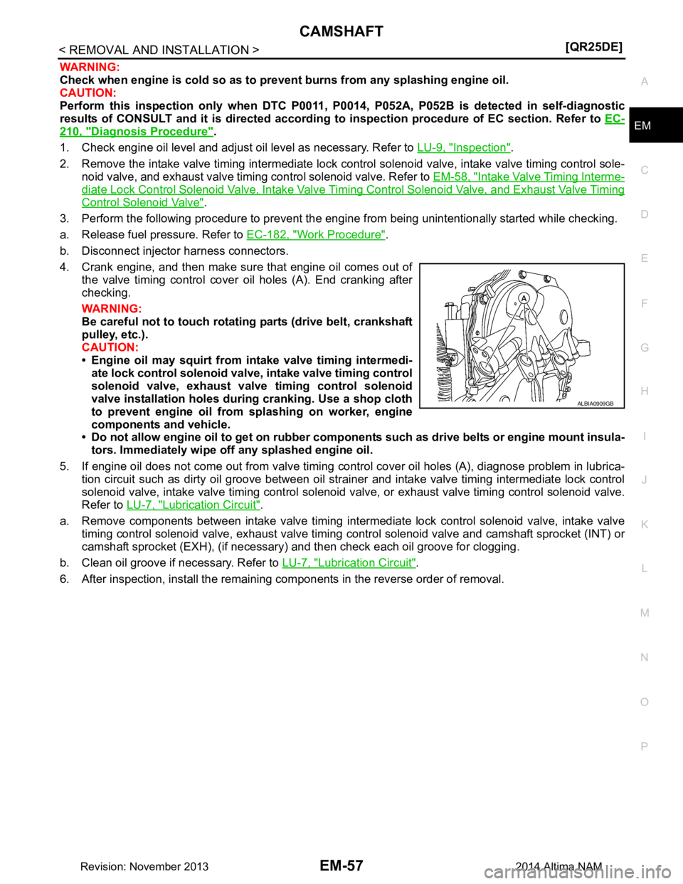
4. Crank engine, and then make sure that engine oil comes out of the valve timing control cover oil holes (A). End cranking after
checking.
WARNING:
Be careful not to touch rotating parts (drive belt, crankshaft
pulley, etc.).
CAUTION:
• Engine oil may squirt from intake valve timing intermedi-
ate lock control solenoid valve, intake valve timing control
solenoid valve, exhaust valve timing control solenoid
valve installation holes during cranking. Use a shop cloth
to prevent engine oil from splashing on worker, engine
components and vehicle.
• Do not allow engine oil to get on rubber componen ts such as drive belts or engine mount insula-
tors. Immediately wipe off any splashed engine oil.
5. If engine oil does not come out from valve timing cont rol cover oil holes (A), diagnose problem in lubrica-
tion circuit such as dirty oil groove between oil strainer and intake valve timing intermediate lock control
solenoid valve, intake valve timing control solenoid valve, or exhaust valve timing control solenoid valve.
Refer to LU-7, "Lubrication Circuit"
.
a. Remove components between intake valve timing intermediate lock control solenoid valve, intake valve timing control solenoid valve, exhaust valve timing c ontrol solenoid valve and camshaft sprocket (INT) or
camshaft sprocket (EXH), (if necessary) and then check each oil groove for clogging.
b. Clean oil groove if necessary. Refer to LU-7, "Lubrication Circuit"
.
6. After inspection, install the remaining components in the reverse order of removal.
ALBIA0909GB
Revision: November 20132014 Altima NAM
Page 2056 of 4801
EM-58
< REMOVAL AND INSTALLATION >[QR25DE]
VALVE TIMING CONTROL
VALVE TIMING CONTROL
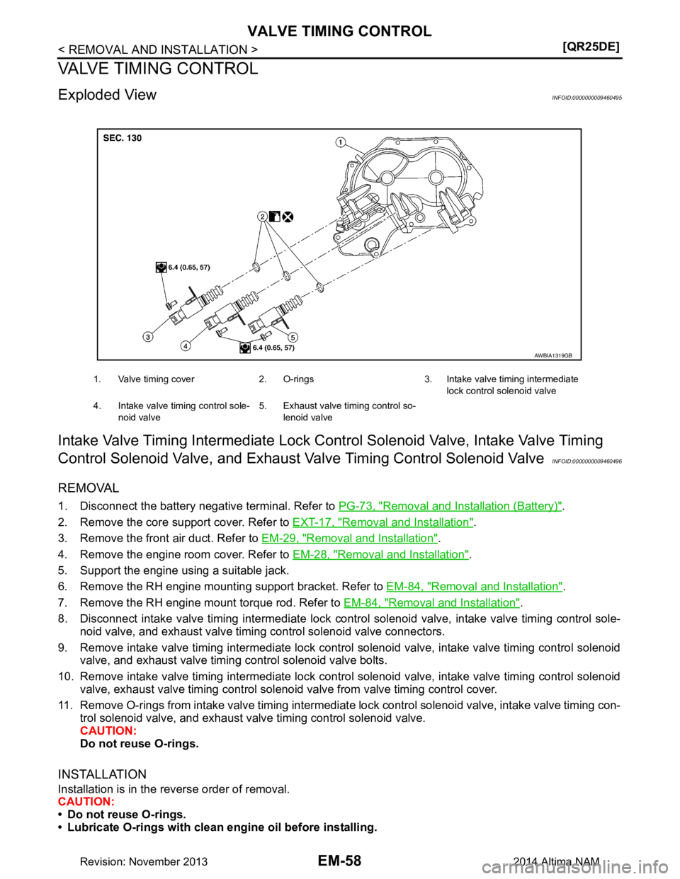
Exploded ViewINFOID:0000000009460495
Intake Valve Timing Intermediate Lock Cont
rol Solenoid Valve, Intake Valve Timing
Control Solenoid Valve, a nd Exhaust Valve Timing Control Solenoid Valve
INFOID:0000000009460496
REMOVAL
1. Disconnect the battery negative terminal. Refer to PG-73, "Removal and Installation (Battery)".
2. Remove the core support cover. Refer to EXT-17, "Removal and Installation"
.
3. Remove the front air duct. Refer to EM-29, "Removal and Installation"
.
4. Remove the engine room cover. Refer to EM-28, "Removal and Installation"
.
5. Support the engine using a suitable jack.
6. Remove the RH engine mounting support bracket. Refer to EM-84, "Removal and Installation"
.
7. Remove the RH engine mount torque rod. Refer to EM-84, "Removal and Installation"
.
8. Disconnect intake valve timing intermediate lock control solenoid valve, intake valve timing control sole- noid valve, and exhaust valve timing control solenoid valve connectors.
9. Remove intake valve timing intermediate lock control solenoid valve, intake valve timing control solenoid valve, and exhaust valve timing control solenoid valve bolts.
10. Remove intake valve timing intermediate lock control solenoid valve, intake valve timing control solenoid valve, exhaust valve timing control solenoid valve from valve timing control cover.
11. Remove O-rings from intake valve timing intermediate lock control solenoid valve, intake valve timing con- trol solenoid valve, and exhaust valve timing control solenoid valve.
CAUTION:
Do not reuse O-rings.
INSTALLATION
Installation is in the reverse order of removal.
CAUTION:
• Do not reuse O-rings.
• Lubricate O-rings with clean en gine oil before installing.
1. Valve timing cover 2. O-rings 3. Intake valve timing intermediate
lock control solenoid valve
4. Intake valve timing control sole- noid valve 5. Exhaust valve timing control so-
lenoid valve
AWBIA1319GB
Revision: November 20132014 Altima NAM