timing NISSAN TEANA 2014 Service Manual
[x] Cancel search | Manufacturer: NISSAN, Model Year: 2014, Model line: TEANA, Model: NISSAN TEANA 2014Pages: 4801, PDF Size: 51.2 MB
Page 1823 of 4801

P0420, P0430 THREE WAY CATALYST FUNCTIONEC-823
< DTC/CIRCUIT DIAGNOSIS > [VQ35DE]
C
D E
F
G H
I
J
K L
M A
EC
NP
O
P0420, P0430 THREE WAY CATALYST FUNCTION
DTC LogicINFOID:0000000009462677
DTC DETECTION LOGIC
The ECM monitors the switching frequency ratio of air fuel ratio (A/F)
sensor 1 and heated oxygen sensor 2.
A three way catalyst (manifold) with high oxygen storage capacity
will indicate a low switching frequency of heated oxygen sensor 2.
As oxygen storage capacity decr eases, the heated oxygen sensor 2
switching frequency will increase.
When the frequency ratio of A/F sensor 1 and heated oxygen sensor
2 approaches a specified limit value, the three way catalyst (mani-
fold) malfunction is diagnosed.
DTC CONFIRMATION PROCEDURE
1.INSPECTION START
Will CONSULT be used?
Will CONSULT be used?
YES >> GO TO 2.
NO >> GO TO 7.
2.PRECONDITIONING
If DTC Confirmation Procedure has been previously conduc ted, always perform the following before conduct-
ing the next test.
1. Turn ignition switch OFF and wait at least 10 seconds.
2. Turn ignition switch ON.
3. Turn ignition switch OFF and wait at least 10 seconds.
TESTING CONDITION:
Do not maintain engine speed for mo re than the specified minutes below.
>> GO TO 3.
3.PERFORM DTC CONFIRMATION PROCEDURE-I
With CONSULT
1. Turn ignition switch ON and select “DATA MONITOR” mode with CONSULT.
2. Start engine and warm it up to the normal operating temperature.
3. Turn ignition switch OFF and wait at least 10 seconds.
4. Turn ignition switch ON.
5. Turn ignition switch OFF and wait at least 10 seconds.
6. Start engine and keep the engine speed between 3,500 and 4,000 rpm for at least 1 minute under no load.
7. Let engine idle for 1 minute.
8. Check that “COOLAN TEMP/S” indicates more than 70 °C (158 °F).
If not, warm up engine and go to next step w hen “COOLAN TEMP/S” indication reaches 70 °C (158 °F).
9. Open engine hood.
10. Select “DTC & SRT CONFIRMATION” then “SRT WORK SUPPORT” mode with CONSULT.
PBIB2055E
DTC No. Trouble diagnosis name DTC detecting condition Possible cause
P0420 Catalyst system efficien-
cy below threshold
(bank 1) • Three way catalyst (manifold) does not oper-
ate properly.
• Three way catalyst (manifold) does not have
enough oxygen storage capacity. • Three way catalyst (manifold)
• Exhaust tube
• Intake air leakage
• Fuel injector
• Fuel injector leakage
• Spark plug
• Improper ignition timing
P0430
Catalyst system efficien-
cy below threshold
(bank 2)
Revision: November 20132014 Altima NAMRevision: November 20132014 Altima NAM
Page 1825 of 4801

P0420, P0430 THREE WAY CATALYST FUNCTIONEC-825
< DTC/CIRCUIT DIAGNOSIS > [VQ35DE]
C
D E
F
G H
I
J
K L
M A
EC
NP
O
Is the inspection result normal?
YES >> INSPECTION END
NO >> Proceed to EC-825, "Diagnosis Procedure"
.
Diagnosis ProcedureINFOID:0000000009462679
1.CHECK EXHAUST SYSTEM
Visually check exhaust tubes and muffler for dents.
Is the inspection result normal?
YES >> GO TO 2.
NO >> Repair or replace malfunctioning part.
2.CHECK EXHAUST GAS LEAKAGE
1. Start engine and run it at idle.
2. Listen for an exhaust gas leakage before the three way catalyst (manifold).
Is exhaust gas leakage detected?
YES >> Repair or replace malfunctioning part.
NO >> GO TO 3.
3.CHECK INTAKE AIR LEAKAGE
Listen for an intake air leakage after the mass air flow sensor.
Is intake air leakage detected?
YES >> Repair or replace malfunctioning part.
NO >> GO TO 4.
4.CHECK IGNITION TIMING
Check idle speed and ignition timing.
For procedure, refer to EC-675, "Work Procedure"
.
For specification, refer to EC-998, "Idle Speed"
and EC-998, "Ignition Timing".
Is the inspection result normal?
YES >> GO TO 5.
NO >> Follow the EC-675, "Work Procedure"
.
5.CHECK FUEL INJECTORS
1. Stop engine and then turn ignition switch ON.
2. Check the voltage between ECM harness connector terminals.
PBIB1216E
Revision: November 20132014 Altima NAMRevision: November 20132014 Altima NAM
Page 1873 of 4801

P050A, P050E COLD START CONTROLEC-873
< DTC/CIRCUIT DIAGNOSIS > [VQ35DE]
C
D E
F
G H
I
J
K L
M A
EC
NP
O
P050A, P050E COLD START CONTROL
DescriptionINFOID:0000000009462723
ECM controls ignition timing and engine idle speed when engine is started with pre-warming up condition.
This control promotes the activation of three way ca talyst by heating the catalyst and reduces emissions.
DTC LogicINFOID:0000000009462724
DTC DETECTION LOGIC
NOTE:
If DTC P050A, P050E is displayed with other DTC, first perform the trouble diagnosis for other DTC.
DTC CONFIRMATION PROCEDURE
1.PRECONDITIONING
If DTC Confirmation Procedure has been previously conducted, always perform the following procedure
before conducting the next test.
1. Turn ignition switch OFF and wait at least 10 seconds.
2. Turn ignition switch ON.
3. Turn ignition switch OFF and wait at least 10 seconds.
TESTING CONDITION:
Before performing the following procedure, confirm that battery voltage is more than 11 V at idle.
>> GO TO 2.
2.PERFORM DTC CONFIRMATION PROCEDURE-I
With CONSULT
1. Turn ignition switch OFF and wait at least 10 seconds.
2. Turn ignition switch ON.
3. Select “DATA MONITOR” mode with CONSULT.
4. Check the indication of “COOLAN TEMP/S”.
With GST
Follow the procedure “With CONSULT” above.
Is the value of
“COOLAN TEMP/S” between 4°C (39°F) and 36°C (97°F)?
YES >> GO TO 3.
NO-1 [If it is below 4 °C (39 °F)]>>Warm up the engine until the value of “COOLAN TEMP/S” reaches 4 °C
(39 °F) or more. Retry from step 1.
NO-2 [If it is above 36 °C (97 °F)]>>Cool engine down to less than 36 °C (97 °F). Retry from step 1.
3.PERFORM DTC CONFIRMATION PROCEDURE-II
With CONSULT
1. Set the select lever in N range.
2. Start the engine and warm up in idle with the value of “COOLAN TEMP/S” between 4°C (39 °F) and 40 °C
(104 °F) for more than 15 seconds.
3. Check 1st trip DTC.
With GST
Follow the procedure “With CONSULT” above.
Is 1st trip DTC detected?
YES >> Proceed to EC-874, "Diagnosis Procedure".
DTC No. Trouble diagnosis name DTC detecting condition Possible cause
P050A Cold start idle air control system
performance ECM does not control engine idle speed properly
when engine is started with pre-warming up con-
dition. • Lack of intake air volume
• Fuel injection system
•ECM
P050E Cold start engine exhaust temper-
ature too low The temperature of the catalyst inlet does not
rise to the proper temperature when the engine
is started with pre-warming up condition.
Revision: November 20132014 Altima NAMRevision: November 20132014 Altima NAM
Page 1987 of 4801

ENGINE CONTROL SYSTEM SYMPTOMSEC-987
< SYMPTOM DIAGNOSIS > [VQ35DE]
C
D E
F
G H
I
J
K L
M A
EC
NP
O
SYMPTOM DIAGNOSIS
ENGINE CONTROL SYSTEM SYMPTOMS
Symptom TableINFOID:0000000009462865
SYSTEM — BASIC ENGINE CONTROL SYSTEM
SYMPTOM
Reference
page
HARD/NO START/RESTART (EXCP. HA)
ENGINE STALL
HESITATION/SURGING/FLAT SPOT
SPARK KNOCK/DETONATION
LACK OF POWER/POOR ACCELERATION
HIGH IDLE/LOW IDLE
ROUGH IDLE/HUNTING
IDLING VIBRATION
SLOW/NO RETURN TO IDLE
OVERHEATS/WATER TEMPERATURE HIGH
EXCESSIVE FUEL CONSUMPTION
EXCESSIVE OIL CONSUMPTION
BATTERY DEAD (UNDER CHARGE)
Warranty symptom code AA AB AC AD AE AF AG AH AJ AK AL AM HA
Fuel Fuel pump circuit 11232 22 3 2 EC-965
Fuel pressure regulator system 334444444 4EC-687
Fuel injector circuit 11232 22 2EC-962
Evaporative emission system 334444444 4EC-580
Air Positive crankcase ventilation sys-
tem 334444444 41
EC-563
Incorrect idle speed adjustment 1 1 1 1 1 EC-675
Electric throttle control actuator 112332222 2 2EC-933,
EC-938
IgnitionIncorrect ignition timing adjustment33111 11 1 EC-675
Ignition circuit 11222 22 2EC-967
Power supply and ground circuit 22333 33 23 EC-709
Mass air flow sensor circuit
1
12 2
222 2 EC-727,
EC-732
Engine coolant temperature sensor circuit
333
EC-742,
EC-746
Air fuel ratio (A/F) sensor 1 circuit EC-753
,
EC-757
,
EC-760
,
EC-781
,
EC-927
Throttle position sensor circuit
22EC-744
,
EC-807
,
EC-895
,
EC-896
,
EC-945
Accelerator pedal position sensor circuit 3 2 1 EC-885
,
EC-940
,
EC-942
,
EC-947
Revision: November 20132014 Altima NAMRevision: November 20132014 Altima NAM
Page 1988 of 4801

EC-988
< SYMPTOM DIAGNOSIS >[VQ35DE]
ENGINE CONTROL SYSTEM SYMPTOMS
1 - 6: The numbers refer to the order of inspection.
(continued on next page)
SYSTEM — ENGINE MECHANICAL & OTHER
Knock sensor circuit 2 3 EC-815
Engine oil temperature sensor 4 2 3EC-801,
EC-805
Crankshaft position sensor (POS) circuit 2 2 EC-817
Camshaft position sensor (PHASE) circuit 3 2EC-820
Vehicle speed signal circuit 2 3 3 3EC-867
ECM 22333333333EC-881,
EC-883
Intake valve timing control solenoid valve cir-
cuit 32 13223 3
EC-725
PNP signal circuit 3 3 3 3 3 EC-887
VIAS control solenoid valve 1 circuit 1EC-920
VIAS control solenoid valve 2 circuit 1EC-922
Refrigerant pressure sensor circuit 2 3 3 4EC-979
Electrical load signal circuit 3EC-957
Air conditioner circuit 223333333 3 2HA-15
ABS actuator and electric unit (control unit) 4BRC-55
SYMPTOM
Reference
page
HARD/NO START/RESTART (EXCP. HA)
ENGINE STALL
HESITATION/SURGING/FLAT SPOT
SPARK KNOCK/DETONATION
LACK OF POWER/POOR ACCELERATION
HIGH IDLE/LOW IDLE
ROUGH IDLE/HUNTING
IDLING VIBRATION
SLOW/NO RETURN TO IDLE
OVERHEATS/WATER TEMPERATURE HIGH
EXCESSIVE FUEL CONSUMPTION
EXCESSIVE OIL CONSUMPTION
BATTERY DEAD (UNDER CHARGE)
Warranty symptom code AA AB AC AD AE AF AG AH AJ AK AL AM HA
Revision: November 20132014 Altima NAMRevision: November 20132014 Altima NAM
Page 1990 of 4801

EC-990
< SYMPTOM DIAGNOSIS >[VQ35DE]
ENGINE CONTROL SYSTEM SYMPTOMS
1 - 6: The numbers refer to the order of inspection.Va l v e
mecha-
nism Timing chain
55555 55 5 EM-182
Camshaft
EM-194
Intake valve timing controlEM-172,
EM-173
Intake valve 3EM-210
Exhaust valve
Exhaust Exhaust manifold/Tube/Muffler/ Gasket 55555 55 5 EM-152
,
EM-153
,
EX-11
Three way catalyst
Lubrica-
tion Oil pan/Oil strainer/Oil pump/Oil
filter/Oil gallery/Oil cooler 55555 55 5 EM-156
,
LU-27
, LU-
29, LU-32
Oil level (Low)/Filthy oil LU-25
Cooling
Radiator/Hose/Radiator filler cap
55555 55 45 CO-40,
CO-51
Thermostat 5 CO-49
Water pumpCO-44
Water galleryCO-31
Cooling fan
5CO-42
Coolant level (Low)/Contaminat-
ed coolant CO-35
NVIS (NISSAN Vehicle Immobilizer System —
NATS) 11
SEC-11
SYMPTOM
Reference
page
HARD/NO START/RESTART (EXCP. HA)
ENGINE STALL
HESITATION/SURGING/FLAT SPOT
SPARK KNOCK/DETONATION
LACK OF POWER/POOR ACCELERATION
HIGH IDLE/LOW IDLE
ROUGH IDLE/HUNTING
IDLING VIBRATION
SLOW/NO RETURN TO IDLE
OVERHEATS/WATER TEMPERATURE HIGH
EXCESSIVE FUEL CONSUMPTION
EXCESSIVE OIL CONSUMPTION
BATTERY DEAD (UNDER CHARGE)
Warranty symptom code AA AB AC AD AE AF AG AH AJ AK AL AM HA
Revision: November 20132014 Altima NAMRevision: November 20132014 Altima NAM
Page 1993 of 4801

IGNITION TIMINGEC-993
< PERIODIC MAINTENANCE > [VQ35DE]
C
D E
F
G H
I
J
K L
M A
EC
NP
O
IGNITION TIMING
Work ProcedureINFOID:0000000009462868
1.CHECK IGNITION TIMING
1. Attach timing light (A) to loop wires as shown.
2. Check ignition timing. >> INSPECTION END
: Vehicle front
ALBIA0809ZZ
JMBIA1135GB
Revision: November 20132014 Altima NAMRevision: November 20132014 Altima NAM
Page 1998 of 4801

EC-998
< SERVICE DATA AND SPECIFICATIONS (SDS) [VQ35DE]
SERVICE DATA AND SPECIFICATIONS (SDS)
SERVICE DATA AND SPECIFICATIONS (SDS)
SERVICE DATA AND SPECIFICATIONS (SDS)
Idle SpeedINFOID:0000000009462872
*: Under the following conditions
• A/C switch: OFF
• Electric load: OFF (Lights, heater fan & rear window defogger)
• Steering wheel: Kept in straight-ahead position
Ignition TimingINFOID:0000000009462873
*: Under the following conditions
• A/C switch: OFF
• Electric load: OFF (Lights, heater fan & rear window defogger)
• Steering wheel: Kept in straight-ahead position
Calculated Load ValueINFOID:0000000009462874
Mass Air Flow SensorINFOID:0000000009462875
*: Engine is warmed up to normal operating temperature and running under no load. Condition Specification
No load* (in P or N position) 650 ± 50 rpm
Condition Specification
No load* (in P or N position) 12 ± 2 ° BTDC
Condition Specification (Using CONSULT or GST)
At idle 10 – 35 %
At 2,500 rpm 10 – 35 %
Supply voltageBattery voltage (11 – 14 V)
Output voltage at idle (in N position) 0.9 – 1.2 V*
Mass air flow (Using CONSULT or GST) 2.0 – 6.0 g/s at idle*
7.0 – 20.0 g/s at 2,500 rpm*
Revision: November 20132014 Altima NAMRevision: November 20132014 Altima NAM
Page 2000 of 4801
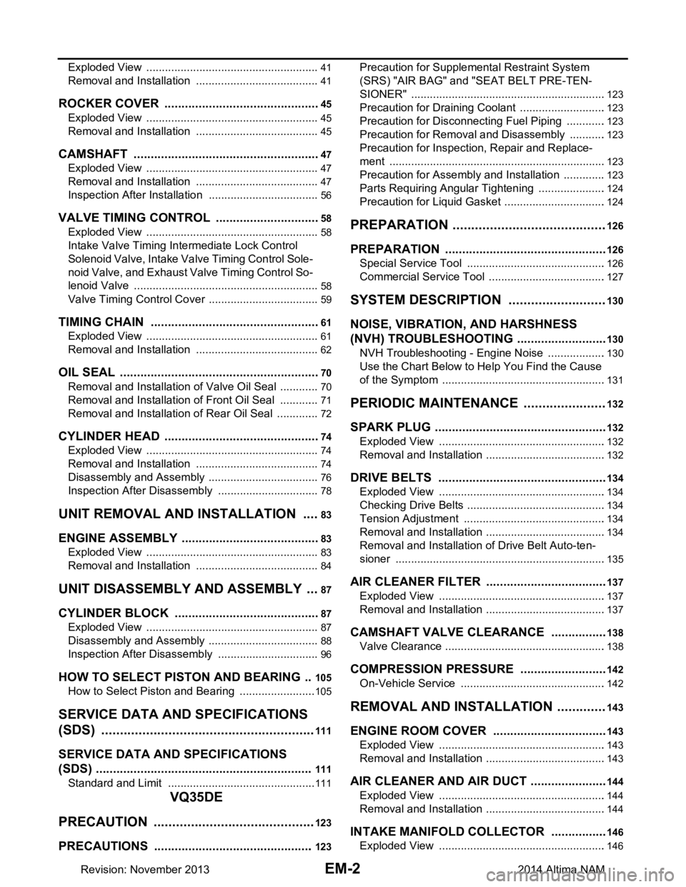
EM-2
Exploded View ........................................................41
Removal and Installation ........................................41
ROCKER COVER ..............................................45
Exploded View ..................................................... ...45
Removal and Installation ........................................45
CAMSHAFT .......................................................47
Exploded View ..................................................... ...47
Removal and Installation ........................................47
Inspection After Installation ................................. ...56
VALVE TIMING CONTROL ............................ ...58
Exploded View ..................................................... ...58
Intake Valve Timing Intermediate Lock Control
Solenoid Valve, Intake Va lve Timing Control Sole-
noid Valve, and Exhaust Valve Timing Control So-
lenoid Valve ......................................................... ...
58
Valve Timing Control Cover ....................................59
TIMING CHAIN ............................................... ...61
Exploded View ..................................................... ...61
Removal and Installation ........................................62
OIL SEAL ...........................................................70
Removal and Installation of Valve Oil Seal .......... ...70
Removal and Installation of Front Oil Seal .............71
Removal and Installation of Rear Oil Seal ..............72
CYLINDER HEAD ..............................................74
Exploded View ..................................................... ...74
Removal and Installation ........................................74
Disassembly and Assembly ....................................76
Inspection After Disassembly .................................78
UNIT REMOVAL AND INSTALLATION .. ...83
ENGINE ASSEMBLY ...................................... ...83
Exploded View ..................................................... ...83
Removal and Installation ........................................84
UNIT DISASSEMBLY AND ASSEMBLY ....87
CYLINDER BLOCK ........................................ ...87
Exploded View ..................................................... ...87
Disassembly and Assembly ....................................88
Inspection After Disassembly .................................96
HOW TO SELECT PISTON AND BEARING .. .105
How to Select Piston and Bearing ....................... ..105
SERVICE DATA AND SPECIFICATIONS
(SDS) .............. ............................................
111
SERVICE DATA AND SPECIFICATIONS
(SDS) ............................................................... .
111
Standard and Limit .............................................. ..111
VQ35DE
PRECAUTION .............. ..............................
123
PRECAUTIONS .............................................. .123
Precaution for Supplemental Restraint System
(SRS) "AIR BAG" and "SEAT BELT PRE-TEN-
SIONER" .............................................................. .
123
Precaution for Draining Coolant ............................123
Precaution for Disconnecting Fuel Piping .............123
Precaution for Removal and Disassembly ............123
Precaution for Inspection, Repair and Replace-
ment ..................................................................... .
123
Precaution for Assembly and Installation ..............123
Parts Requiring Angular Tightening ..................... .124
Precaution for Liquid Gasket .................................124
PREPARATION .........................................126
PREPARATION .............................................. ..126
Special Service Tool ............................................ .126
Commercial Service Tool ......................................127
SYSTEM DESCRIPTION ..........................130
NOISE, VIBRATION, AND HARSHNESS
(NVH) TROUBLESHOOTING ......................... ..
130
NVH Troubleshooting - Engine Noise .................. .130
Use the Chart Below to Help You Find the Cause
of the Symptom .................................................... .
131
PERIODIC MAINTENANCE ......................132
SPARK PLUG ... .............................................. ..132
Exploded View ..................................................... .132
Removal and Installation .......................................132
DRIVE BELTS ................................................ ..134
Exploded View ..................................................... .134
Checking Drive Belts .............................................134
Tension Adjustment ..............................................134
Removal and Installation .......................................134
Removal and Installation of Drive Belt Auto-ten-
sioner ................................................................... .
135
AIR CLEANER FILTER ....................................137
Exploded View ..................................................... .137
Removal and Installation .......................................137
CAMSHAFT VALVE CLEARANCE ............... ..138
Valve Clearance ................................................... .138
COMPRESSION PRESSURE ..........................142
On-Vehicle Service .............................................. .142
REMOVAL AND INSTALLATION .............143
ENGINE ROOM COVER ................................ ..143
Exploded View ..................................................... .143
Removal and Installation .......................................143
AIR CLEANER AND AIR DUCT ..................... ..144
Exploded View ..................................................... .144
Removal and Installation .......................................144
INTAKE MANIFOLD COLLECTOR ............... ..146
Exploded View ..................................................... .146
Revision: November 20132014 Altima NAM
Page 2001 of 4801

EM-3
C
D E
F
G H
I
J
K L
M
EM A
N
O P
Removal and Installation
.......................................
146
INTAKE MANIFOLD ....................................... ..149
Exploded View .................................................... ..149
Removal and Installation .......................................149
EXHAUST MANIFOLD AND THREE WAY
CATALYST ..................................................... ..
151
Exploded View .................................................... ..151
Removal and Installation (LH) ...............................152
Removal and Installation (RH) ..............................153
OIL PAN AND OIL STRAINER ...................... ..156
Exploded View .................................................... ..156
Removal and Installation (Lower Oil Pan) .............156
Removal and Installation (Upper Oil Pan) .............157
IGNITION COIL ................................................162
Exploded View .................................................... ..162
Removal and Installation LH .................................162
Removal and Installation RH .................................162
FUEL INJECTOR AND FUEL TUBE ...............163
Exploded View .................................................... ..163
Removal and Installation .......................................163
ROCKER COVER ........................................... ..168
Exploded View .................................................... ..168
Removal and Installation LH .................................168
Removal and Installation RH .................................169
INTAKE VALVE TIMING CONTROL ...............172
Exploded View .................................................... ..172
Intake Valve Timing Control Solenoid Valve (LH)
(bank 2) ............................................................... ..
172
Intake Valve Timing Control Solenoid Valve (RH)
(bank 1) ............................................................... ..
173
FRONT TIMING CHAIN CASE .........................174
Exploded View .................................................... ..174
Removal and Installation .......................................174
TIMING CHAIN ............................................... ..182
Exploded View .................................................... ..182
Removal and Installation .......................................182
REAR TIMING CHAIN CASE ......................... ..189
Exploded View .................................................... ..189
Removal and Installation .......................................189
CAMSHAFT .................................................... ..194
Exploded View ..................................................... ..194
Removal and Installation .......................................194
Inspection after Installation ....................................202
OIL SEAL ........................................................203
Removal and Installation of Valve Oil Seal .......... ..203
Removal and Installation of Front Oil Seal ............203
Removal and Installation of Rear Oil Seal .............205
CYLINDER HEAD ...........................................207
Exploded View ..................................................... ..207
Removal and Installation .......................................207
Disassembly and Assembly ...................................210
Inspection After Disassembly ................................212
ENGINE MOUNT .............................................217
ENGINE MOUNT (FRONT) .................................... ..217
ENGINE MOUNT (FRONT) : Removal and Instal-
lation .................................................................... ..
217
UNIT REMOVAL AND INSTALLATION ....220
ENGINE ASSEMBLY ......................................220
Exploded View ..................................................... ..220
Removal and Installation .......................................220
UNIT DISASSEMBLY AND ASSEMBLY ..224
CYLINDER BLOCK .........................................224
Disassembly and Assembly ................................. ..224
Inspection ..............................................................234
Dowel Pin Alignment .............................................244
SERVICE DATA AND SPECIFICATIONS
(SDS) ............... ...........................................
246
SERVICE DATA AND SPECIFICATIONS
(SDS) ...............................................................
246
General Specification .......................................... ..246
Drive Belt ...............................................................246
Spark Plug .............................................................247
Intake Manifold ......................................................247
Exhaust Manifold ..................................................247
Camshaft ...............................................................247
Cylinder Head .......................................................249
Cylinder Block .......................................................252
Main Bearing .........................................................255
Connecting Rod Bearing ......................................256
Drive Plate .............................................................257
Revision: November 20132014 Altima NAM