Maf NISSAN TEANA 2014 Service Manual
[x] Cancel search | Manufacturer: NISSAN, Model Year: 2014, Model line: TEANA, Model: NISSAN TEANA 2014Pages: 4801, PDF Size: 51.2 MB
Page 1003 of 4801
EC-3
C
D E
F
G H
I
J
K L
M
EC A
N
O P
Description ..........................................................
..
181
Work Procedure ....................................................181
FUEL PRESSURE .......................................... ..182
Work Procedure .................................................. ..182
HOW TO SET SRT CODE ................................183
Description .......................................................... ..183
SRT Set Driving Pattern ........................................184
Work Procedure ....................................................186
HOW TO ERASE PERMANENT DTC ..............189
Description .......................................................... ..189
Work Procedure (Group A) ...................................190
Work Procedure (Group B) ...................................192
DTC/CIRCUIT DIAGNOSIS .......................195
TROUBLE DIAGNOSIS - SPECIFICATION
VALUE ............................................................ ..
195
Description .......................................................... ..195
Component Function Check ..................................195
Diagnosis Procedure .............................................196
POWER SUPPLY AND GROUND CIRCUIT ....203
Diagnosis Procedure ........................................... ..203
U0101 CAN COMM CIRCUIT ...........................207
Description .......................................................... ..207
DTC Logic .............................................................207
Diagnosis Procedure .............................................207
U1001 CAN COMM CIRCUIT ...........................208
Description .......................................................... ..208
DTC Logic .............................................................208
Diagnosis Procedure .............................................208
P0011 IVT CONTROL ......................................209
DTC Logic ........................................................... ..209
Diagnosis Procedure .............................................210
Component Inspection ..........................................211
P0014 EVT CONTROL .....................................212
DTC Logic ........................................................... ..212
Diagnosis Procedure .............................................213
Component Inspection ..........................................214
P0031, P0032 A/F SENSOR 1 HEATER .........215
DTC Logic ........................................................... ..215
Diagnosis Procedure .............................................215
Component Inspection ..........................................216
P0037, P0038 HO2S2 HEATER .......................218
DTC Logic ........................................................... ..218
Diagnosis Procedure .............................................218
Component Inspection ..........................................219
P0075 INTAKE VALVE TIMING CONTROL ....221
DTC Logic ........................................................... ..221
Diagnosis Procedure .............................................221
Component Inspection (IVT Control Solenoid
Valve) .................................................................. ..
223
Component Inspection (IVT Intermediate Lock
Control Solenoid Valve) ....................................... ..
224
P0078 EVT CONTROL SOLENOID VALVE ...225
DTC Logic ..............................................................225
Diagnosis Procedure .............................................225
Component Inspection ...........................................226
P0101 MAF SENSOR .....................................228
DTC Logic ..............................................................228
Diagnosis Procedure .............................................228
Component Inspection ...........................................230
P0102, P0103 MAF SENSOR .........................232
DTC Logic ..............................................................232
Diagnosis Procedure .............................................232
Component Inspection ...........................................234
P010A MANIFOLD ABSOLUTE PRESSURE
SENSOR ..........................................................
236
DTC Logic ............................................................ ..236
Diagnosis Procedure .............................................236
Component Inspection (MAP Sensor) ...................237
P0111 IAT SENSOR .......................................239
DTC Logic ..............................................................239
Component Function Check ..................................240
Diagnosis Procedure .............................................240
Component Inspection ...........................................240
P0112, P0113 IAT SENSOR ...........................241
DTC Logic ..............................................................241
Diagnosis Procedure .............................................241
Component Inspection ...........................................242
P0116 ECT SENSOR ......................................243
DTC Logic ..............................................................243
Component Function Check ..................................244
Diagnosis Procedure .............................................244
Component Inspection ...........................................244
P0117, P0118 ECT SENSOR ..........................245
DTC Logic ..............................................................245
Diagnosis Procedure .............................................245
Component Inspection ...........................................246
P0122, P0123 TP SENSOR ............................248
DTC Logic ..............................................................248
Diagnosis Procedure .............................................248
Component Inspection ...........................................250
P0125 ECT SENSOR ......................................251
DTC Logic ..............................................................251
Diagnosis Procedure .............................................251
Component Inspection ...........................................252
P0127 IAT SENSOR .......................................253
DTC Logic ..............................................................253
Diagnosis Procedure .............................................253
Component Inspection ...........................................254
P0128 THERMOSTAT FUNCTION .................255
Revision: November 20132014 Altima NAMRevision: November 20132014 Altima NAM
Page 1010 of 4801
EC-10
POWER SUPPLY AND GROUND CIRCUIT ...709
Diagnosis Procedure ........................................... ..709
U0101 CAN COMM CIRCUIT ..........................713
Description ........................................................... ..713
DTC Logic ..............................................................713
Diagnosis Procedure .............................................713
U1001 CAN COMM CIRCUIT ..........................714
Description ........................................................... ..714
DTC Logic ..............................................................714
Diagnosis Procedure .............................................714
P0011, P0021 IVT CONTROL .........................715
DTC Logic ............................................................ ..715
Diagnosis Procedure .............................................716
Component Inspection ...........................................717
P0031, P0032, P0051, P0052 A/F SENSOR 1
HEATER .......................................................... .
719
DTC Logic ............................................................ ..719
Diagnosis Procedure .............................................719
Component Inspection ...........................................720
P0037, P0038, P0057, P0058 HO2S2 HEAT-
ER ................................................................... .
722
DTC Logic ............................................................ ..722
Diagnosis Procedure .............................................722
Component Inspection ...........................................723
P0075, P0081 IVT CONTROL SOLENOID
VALVE ............................................................ .
725
DTC Logic ............................................................ ..725
Diagnosis Procedure .............................................725
Component Inspection ...........................................726
P0101 MAF SENSOR ......................................727
DTC Logic ............................................................ ..727
Diagnosis Procedure .............................................727
Component Inspection ...........................................729
P0102, P0103 MAF SENSOR ..........................732
DTC Logic ............................................................ ..732
Diagnosis Procedure .............................................732
Component Inspection ...........................................733
P0111 IAT SENSOR ........................................736
DTC Logic ............................................................ ..736
Component Function Check ..................................737
Diagnosis Procedure .............................................737
Component Inspection ...........................................737
P0112, P0113 IAT SENSOR ............................738
DTC Logic ............................................................ ..738
Diagnosis Procedure .............................................738
Component Inspection ...........................................739
P0116 ECT SENSOR .......................................740
DTC Logic ............................................................ ..740
Component Function Check ..................................741
Diagnosis Procedure .............................................741
Component Inspection ......................................... .741
P0117, P0118 ECT SENSOR ...........................742
DTC Logic ............................................................ .742
Diagnosis Procedure .............................................742
Component Inspection ..........................................743
P0122, P0123 TP SENSOR ..............................744
DTC Logic ............................................................ .744
Diagnosis Procedure .............................................744
Component Inspection ..........................................745
P0125 ECT SENSOR .......................................746
DTC Logic ............................................................ .746
Diagnosis Procedure .............................................746
Component Inspection ..........................................747
P0127 IAT SENSOR .........................................748
DTC Logic ............................................................ .748
Diagnosis Procedure .............................................748
Component Inspection ..........................................749
P0128 THERMOSTAT FUNCTION ..................750
DTC Logic ............................................................ .750
Diagnosis Procedure .............................................751
Component Inspection ..........................................751
P0130, P0150 A/F SENSOR 1 .........................753
DTC Logic ............................................................ .753
Component Function Check .................................754
Diagnosis Procedure .............................................755
P0131, P0151 A/F SENSOR 1 .........................757
DTC Logic ............................................................ .757
Diagnosis Procedure .............................................758
P0132, P0152 A/F SENSOR 1 .........................760
DTC Logic ............................................................ .760
Diagnosis Procedure .............................................761
P0137, P0157 HO2S2 .......................................763
DTC Logic ............................................................ .763
Component Function Check .................................764
Diagnosis Procedure .............................................765
Component Inspection ..........................................766
P0138, P0158 HO2S2 .......................................768
DTC Logic ............................................................ .768
Component Function Check .................................769
Diagnosis Procedure .............................................770
Component Inspection ..........................................773
P0139, P0159 HO2S2 .......................................775
DTC Logic ............................................................ .775
Component Function Check .................................776
Diagnosis Procedure .............................................777
Component Inspection ..........................................778
P014C, P014D, P014E, P014F, P015A,
P015B, P015C, P015D A/F SENSOR 1 ......... ..
781
DTC Logic ............................................................ .781
Diagnosis Procedure .............................................783
Revision: November 20132014 Altima NAMRevision: November 20132014 Altima NAM
Page 1028 of 4801
EC-28
< SYSTEM DESCRIPTION >[QR25DE]
COMPONENT PARTS
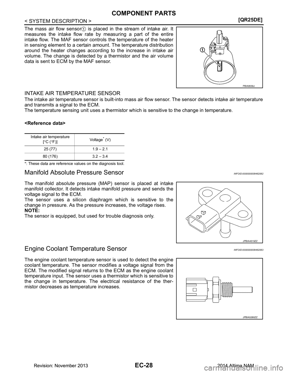
The mass air flow sensor is placed in the stream of intake air. It
measures the intake flow rate by measuring a part of the entire
intake flow. The MAF sensor controls the temperature of the heater
in sensing element to a certain amount. The temperature distribution
around the heater changes according to the increase in intake air
volume. The change is detected by a thermistor and the air volume
data is sent to ECM by the MAF sensor.
INTAKE AIR TEMPERATURE SENSOR
The intake air temperature sensor is built-into mass air flow sensor. The sensor detects intake air temperature
and transmits a signal to the ECM.
The temperature sensing unit uses a thermistor wh ich is sensitive to the change in temperature.
*: These data are reference values on the diagnosis tool.
Manifold Absolute Pressure SensorINFOID:0000000009462062
The manifold absolute pressure (MAP) sensor is placed at intake
manifold collector. It detects intake manifold pressure and sends the
voltage signal to the ECM.
The sensor uses a silicon diaphragm which is sensitive to the
change in pressure. As the pressure increases, the voltage rises.
NOTE:
The sensor is equipped, but used for trouble diagnosis only.
Engine Coolant Te mperature SensorINFOID:0000000009462063
The engine coolant temperature sensor is used to detect the engine
coolant temperature. The sensor modifies a voltage signal from the
ECM. The modified signal returns to the ECM as the engine coolant
temperature input. The sensor uses a thermistor which is sensitive to
the change in temperature. The elec trical resistance of the ther-
mistor decreases as temperature increases.
PBIA9559J
Intake air temperature
[° C ( °F)] Vo l ta g e* (V)
25 (77) 1.9 – 2.1
80 (176) 3.2 – 3.4
JPBIA4619ZZ
JPBIA5280ZZ
Revision: November 20132014 Altima NAMRevision: November 20132014 Altima NAM
Page 1106 of 4801
EC-106
< ECU DIAGNOSIS INFORMATION >[QR25DE]
ECM
P0000 0000NO DTC IS DETECTED.
FURTHER TESTING
MAY BE REQUIRED. ——
Flashing*6— —
P0011 0011 INT/V TIM CONT-B1 ×2 × BEC-209
P0014 0014 EXH/V TIM CONT-B1 — 2 ×BEC-212
P0031 0031 A/F SEN1 HTR (B1) — 2 ×BEC-215
P0032 0032 A/F SEN1 HTR (B1) — 2 ×BEC-215
P0037 0037 HO2S2 HTR (B1) — 2 ×BEC-218
P0038 0038 HO2S2 HTR (B1) — 2 ×BEC-218
P0075 0075 INT/V TIM V/CIR-B1 — 2 ×BEC-221
P0078 0078 EX V/T ACT/CIRC-B1 — 2 ×BEC-225
P0101 0101 MAF SEN/CIRCUIT-B1 — 2 ×BEC-228
P0102 0102 MAF SEN/CIRCUIT-B1 — 1 ×BEC-232
P0103 0103 MAF SEN/CIRCUIT-B1 — 1 ×BEC-232
P010A 010A ABSL PRES SEN/CIRC — 2 — B EC-236
P0111 0111 IAT SENSOR 1 B1 — 2×AEC-239
P0112 0112 IAT SEN/CIRCUIT-B1 — 2 ×BEC-241
P0113 0113 IAT SEN/CIRCUIT-B1 — 2 ×BEC-241
P0116 0116 ECT SEN/CIRC — 2 ×AEC-243
P0117 0117 ECT SEN/CIRC — 1 ×BEC-245
P0118 0118 ECT SEN/CIRC — 1 ×BEC-245
P0122 0122 TP SEN 2/CIRC-B1 — 1 ×BEC-248
P0123 0123 TP SEN 2/CIRC-B1 — 1 ×BEC-248
P0125 0125 ECT SENSOR — 2 ×BEC-251
P0127 0127 IAT SENSOR-B1 — 2 ×BEC-253
P0128 0128 THERMSTAT FNCTN — 2 ×AEC-255
P0130 0130 A/F SENSOR1 (B1) — 2 ×AEC-258
P0131 0131 A/F SENSOR1 (B1) — 2 ×BEC-262
P0132 0132 A/F SENSOR1 (B1) — 2 ×BEC-265
P0137 0137 HO2S2 (B1) ×2 × AEC-268
P0138 0138 HO2S2 (B1) ×2 × AEC-274
P0139 0139 HO2S2 (B1) ×2 × AEC-282
P014C 014C A/F SENSOR1 (B1) ×2 × AEC-289
P014D 014D A/F SENSOR1 (B1) ×2 × AEC-289
P015A 015A A/F SENSOR1 (B1) ×2 × AEC-289
P015B 015B A/F SENSOR1 (B1) ×2 × AEC-289
P0171 0171 FUEL SYS-LEAN-B1 — 2 ×BEC-294
P0172 0172 FUEL SYS-RICH-B1 — 2 ×BEC-298
P0181 0181 FTT SENSOR — 2 ×A and B EC-302
P0182 0182 FTT SEN/CIRCUIT — 2 ×BEC-306
P0183 0183 FTT SEN/CIRCUIT — 2 ×BEC-306
P0196 0196 EOT SENSOR — 2 ×A and B EC-309
P0197 0197 EOT SEN/CIRC — 2 ×BEC-312
DTC*1
Items
(CONSULT screen terms) SRT
code Trip MIL Permanent
DTC group*4Reference page
CONSULT
GST
*2ECM*3
Revision: November 20132014 Altima NAMRevision: November 20132014 Altima NAM
Page 1228 of 4801
EC-228
< DTC/CIRCUIT DIAGNOSIS >[QR25DE]
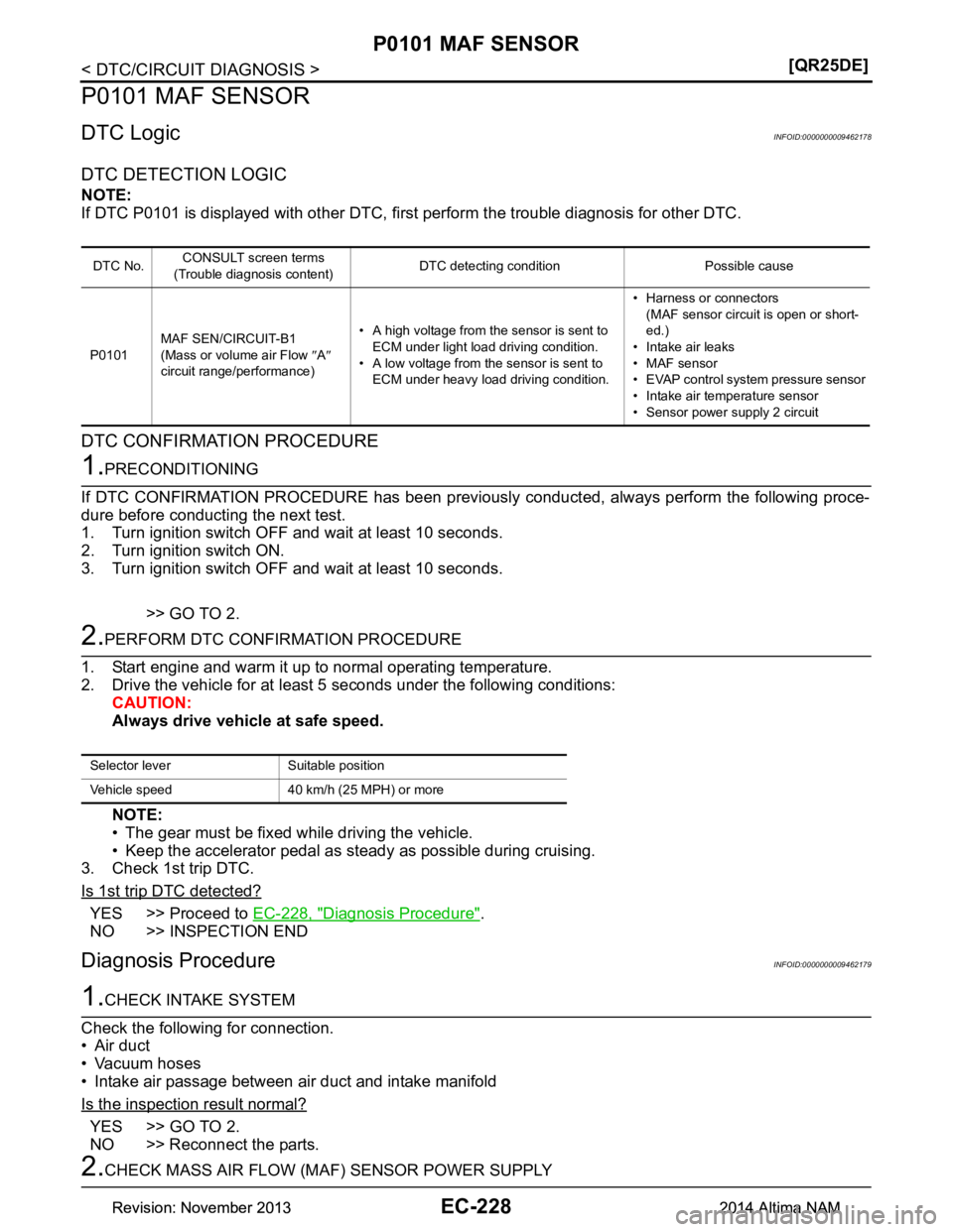
P0101 MAF SENSOR
P0101 MAF SENSOR
DTC LogicINFOID:0000000009462178
DTC DETECTION LOGIC
NOTE:
If DTC P0101 is displayed with other DTC, fi rst perform the trouble diagnosis for other DTC.
DTC CONFIRMATION PROCEDURE
1.PRECONDITIONING
If DTC CONFIRMATION PROCEDURE has been previously conducted, always perform the following proce-
dure before conducting the next test.
1. Turn ignition switch OFF and wait at least 10 seconds.
2. Turn ignition switch ON.
3. Turn ignition switch OFF and wait at least 10 seconds.
>> GO TO 2.
2.PERFORM DTC CONFIRMATION PROCEDURE
1. Start engine and warm it up to normal operating temperature.
2. Drive the vehicle for at least 5 seconds under the following conditions: CAUTION:
Always drive vehicle at safe speed.
NOTE:
• The gear must be fixed while driving the vehicle.
• Keep the accelerator pedal as st eady as possible during cruising.
3. Check 1st trip DTC.
Is 1st trip DTC detected?
YES >> Proceed to EC-228, "Diagnosis Procedure".
NO >> INSPECTION END
Diagnosis ProcedureINFOID:0000000009462179
1.CHECK INTAKE SYSTEM
Check the following for connection.
• Air duct
• Vacuum hoses
• Intake air passage between air duct and intake manifold
Is the inspection result normal?
YES >> GO TO 2.
NO >> Reconnect the parts.
2.CHECK MASS AIR FLOW (M AF) SENSOR POWER SUPPLY
DTC No.CONSULT screen terms
(Trouble diagnosis content) DTC detecting condition Possible cause
P0101 MAF SEN/CIRCUIT-B1
(Mass or volume air Flow ″A ″
circuit range/performance) • A high voltage from the sensor is sent to
ECM under light load driving condition.
• A low voltage from the sensor is sent to ECM under heavy load driving condition. • Harness or connectors
(MAF sensor circuit is open or short-
ed.)
• Intake air leaks
• MAF sensor
• EVAP control system pressure sensor
• Intake air temperature sensor
• Sensor power supply 2 circuit
Selector lever Suitable position
Vehicle speed 40 km/h (25 MPH) or more
Revision: November 20132014 Altima NAMRevision: November 20132014 Altima NAM
Page 1229 of 4801
P0101 MAF SENSOREC-229
< DTC/CIRCUIT DIAGNOSIS > [QR25DE]
C
D E
F
G H
I
J
K L
M A
EC
NP
O
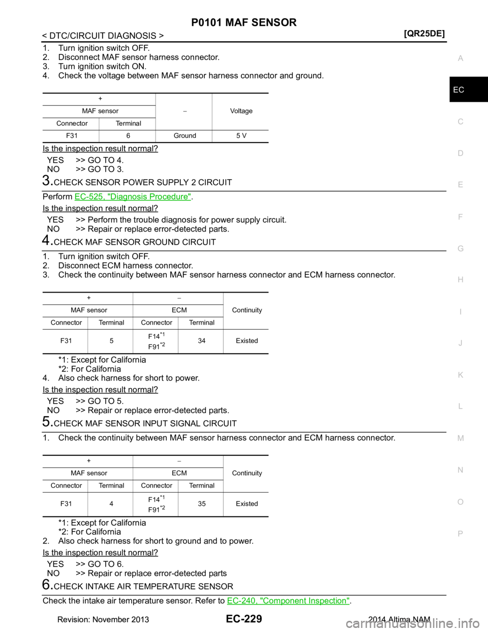
1. Turn ignition switch OFF.
2. Disconnect MAF sensor harness connector.
3. Turn ignition switch ON.
4. Check the voltage between MAF sensor harness connector and ground.
Is the inspection result normal?
YES >> GO TO 4.
NO >> GO TO 3.
3.CHECK SENSOR POWER SUPPLY 2 CIRCUIT
Perform EC-525, "Diagnosis Procedure"
.
Is the inspection result normal?
YES >> Perform the trouble diagnosis for power supply circuit.
NO >> Repair or replace error-detected parts.
4.CHECK MAF SENSOR GROUND CIRCUIT
1. Turn ignition switch OFF.
2. Disconnect ECM harness connector.
3. Check the continuity between MAF sensor harness connector and ECM harness connector.
*1: Except for California
*2: For California
4. Also check harness for short to power.
Is the inspection result normal?
YES >> GO TO 5.
NO >> Repair or replace error-detected parts.
5.CHECK MAF SENSOR INPUT SIGNAL CIRCUIT
1. Check the continuity between MAF sensor harness connector and ECM harness connector.
*1: Except for California
*2: For California
2. Also check harness for short to ground and to power.
Is the inspection result normal?
YES >> GO TO 6.
NO >> Repair or replace error-detected parts
6.CHECK INTAKE AIR TEMPERATURE SENSOR
Check the intake air temperature sensor. Refer to EC-240, "Component Inspection"
.
+
−Vo l ta g e
MAF sensor
Connector Terminal F31 6 Ground 5 V
+ −
Continuity
MAF sensor ECM
Connector Terminal Connector Terminal
F31 5 F14
*1
F91*234 Existed
+
−
Continuity
MAF sensor ECM
Connector Terminal Connector Terminal
F31 4 F14
*1
F91*235 Existed
Revision: November 20132014 Altima NAMRevision: November 20132014 Altima NAM
Page 1230 of 4801
EC-230
< DTC/CIRCUIT DIAGNOSIS >[QR25DE]
P0101 MAF SENSOR
Is the inspection result normal?
YES >> GO TO 7.
NO >> Replace MAF sensor (with intake air temperature sensor). Refer to EM-29, "Exploded View"
.
7.CHECK EVAP CONTROL SYSTEM PRESSURE SENSOR
Check the EVAP control system pressure sensor. Refer to EC-361, "Component Inspection"
.
Is the inspection result normal?
YES >> GO TO 8.
NO >> Replace EVAP control system pressure sensor. Refer to FL-18, "Removal and Installation"
.
8.CHECK MAF SENSOR
Check the MAF sensor. Refer to EC-230, "Component Inspection"
.
Is the inspection result normal?
YES >> Check intermittent incident. Refer to GI-43, "Intermittent Incident".
NO >> Replace MAF sensor. Refer to EM-29, "Exploded View"
.
Component InspectionINFOID:0000000009462180
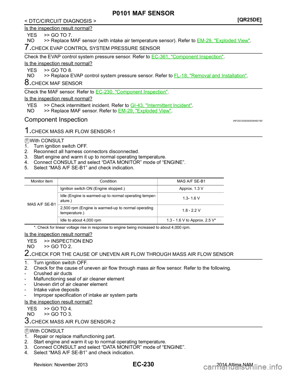
1.CHECK MASS AIR FLOW SENSOR-1
With CONSULT
1. Turn ignition switch OFF.
2. Reconnect all harness connectors disconnected.
3. Start engine and warm it up to normal operating temperature.
4. Connect CONSULT and select “DATA MONITOR” mode of “ENGINE”.
5. Select “MAS A/F SE-B1” and check indication.
*: Check for linear voltage rise in response to engine being increased to about 4,000 rpm.
Is the inspection result normal?
YES >> INSPECTION END
NO >> GO TO 2.
2.CHECK FOR THE CAUSE OF UNEVEN AIR FL OW THROUGH MASS AIR FLOW SENSOR
1. Turn ignition switch OFF.
2. Check for the cause of uneven air flow through mass air flow sensor. Refer to the following.
- Crushed air ducts
- Malfunctioning seal of air cleaner element
- Uneven dirt of air cleaner element
- Intake valve deposits
- Improper specification of intake air system parts
Is the inspection result normal?
YES >> GO TO 4.
NO >> GO TO 3.
3.CHECK MASS AIR FLOW SENSOR-2
With CONSULT
1. Repair or replace malfunctioning part.
2. Start engine and warm it up to normal operating temperature.
3. Connect CONSULT and select “DATA MONITOR” mode of “ENGINE”.
4. Select “MAS A/F SE-B1” and check indication.
Monitor item Condition MAS A/F SE-B1
MAS A/F SE-B1 Ignition switch ON (Engine stopped.) Approx. 1.3 V
Idle (Engine is warmed-up to normal operating temper-
ature.) 1.3- 1.6 V
2,500 rpm (Engine is warmed-up to normal operating
temperature.) 1.8 - 2.2 V
Idle to about 4,000 rpm 1.3 - 1.6 V to Approx. 2.5 V*
Revision: November 20132014 Altima NAMRevision: November 20132014 Altima NAM
Page 1231 of 4801
P0101 MAF SENSOREC-231
< DTC/CIRCUIT DIAGNOSIS > [QR25DE]
C
D E
F
G H
I
J
K L
M A
EC
NP
O
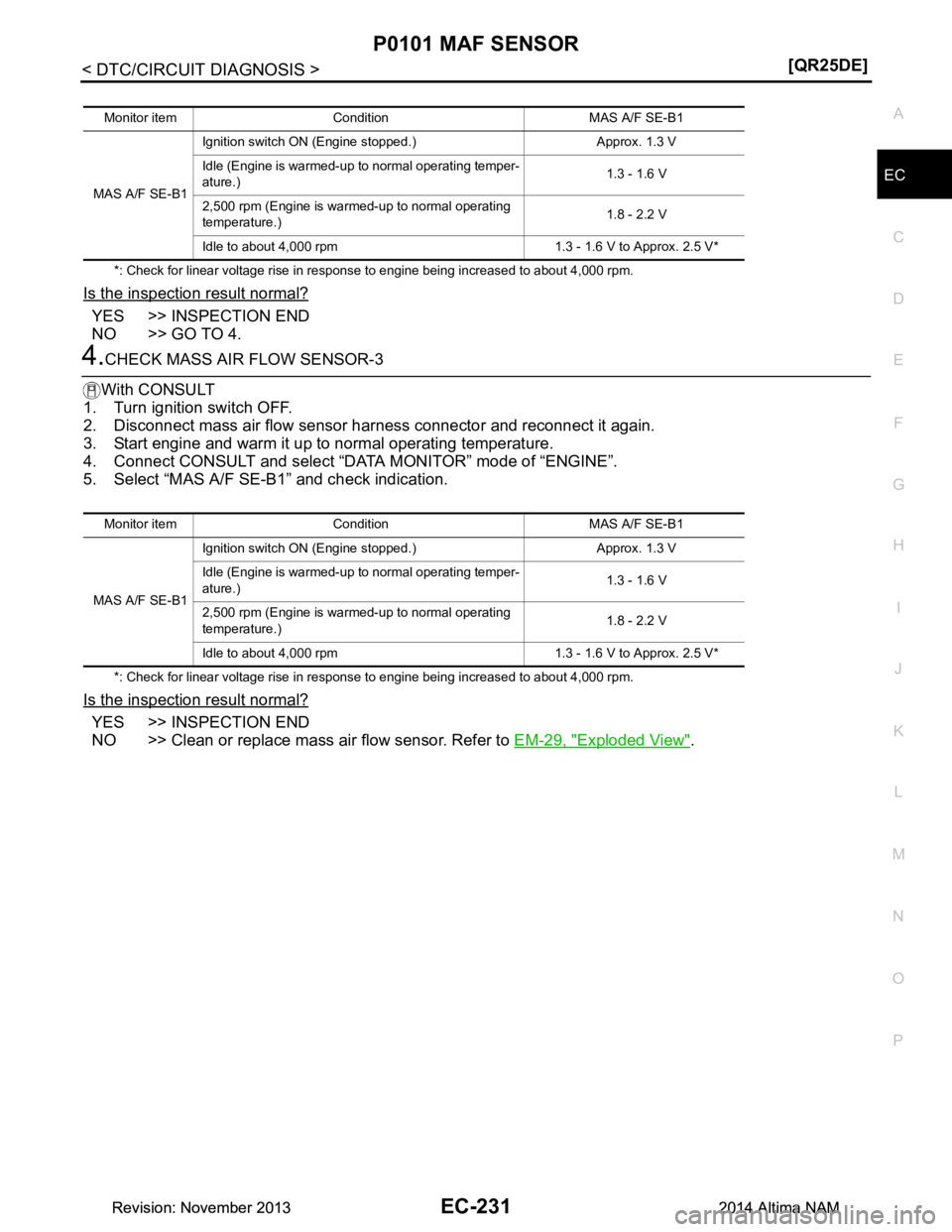
*: Check for linear voltage rise in response to engine being increased to about 4,000 rpm.
Is the inspection result normal?
YES >> INSPECTION END
NO >> GO TO 4.
4.CHECK MASS AIR FLOW SENSOR-3
With CONSULT
1. Turn ignition switch OFF.
2. Disconnect mass air flow sensor har ness connector and reconnect it again.
3. Start engine and warm it up to normal operating temperature.
4. Connect CONSULT and select “DATA MONITOR” mode of “ENGINE”.
5. Select “MAS A/F SE-B1” and check indication.
*: Check for linear voltage rise in response to engine being increased to about 4,000 rpm.
Is the inspection result normal?
YES >> INSPECTION END
NO >> Clean or replace mass air flow sensor. Refer to EM-29, "Exploded View"
.
Monitor item Condition MAS A/F SE-B1
MAS A/F SE-B1 Ignition switch ON (Engine stopped.) Approx. 1.3 V
Idle (Engine is warmed-up to normal operating temper-
ature.) 1.3 - 1.6 V
2,500 rpm (Engine is warmed-up to normal operating
temperature.) 1.8 - 2.2 V
Idle to about 4,000 rpm 1.3 - 1.6 V to Approx. 2.5 V*
Revision: November 20132014 Altima NAMRevision: November 20132014 Altima NAM
Page 1232 of 4801
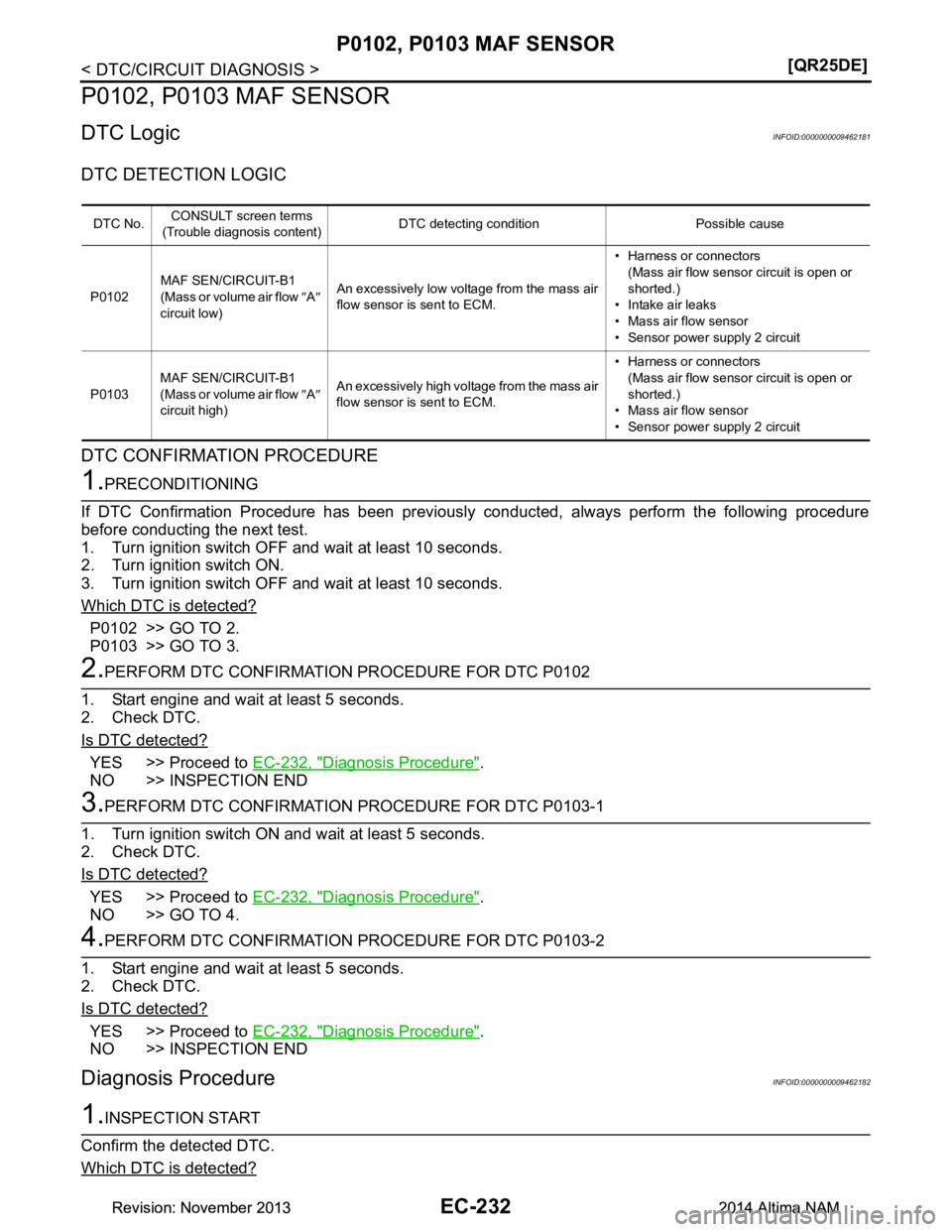
EC-232
< DTC/CIRCUIT DIAGNOSIS >[QR25DE]
P0102, P0103 MAF SENSOR
P0102, P0103 MAF SENSOR
DTC LogicINFOID:0000000009462181
DTC DETECTION LOGIC
DTC CONFIRMATION PROCEDURE
1.PRECONDITIONING
If DTC Confirmation Procedure has been previously conducted, always perform the following procedure
before conducting the next test.
1. Turn ignition switch OFF and wait at least 10 seconds.
2. Turn ignition switch ON.
3. Turn ignition switch OFF and wait at least 10 seconds.
Which DTC is detected?
P0102 >> GO TO 2.
P0103 >> GO TO 3.
2.PERFORM DTC CONFIRMATION PROCEDURE FOR DTC P0102
1. Start engine and wait at least 5 seconds.
2. Check DTC.
Is DTC detected?
YES >> Proceed to EC-232, "Diagnosis Procedure".
NO >> INSPECTION END
3.PERFORM DTC CONFIRMATION PROCEDURE FOR DTC P0103-1
1. Turn ignition switch ON and wait at least 5 seconds.
2. Check DTC.
Is DTC detected?
YES >> Proceed to EC-232, "Diagnosis Procedure".
NO >> GO TO 4.
4.PERFORM DTC CONFIRMATION PROCEDURE FOR DTC P0103-2
1. Start engine and wait at least 5 seconds.
2. Check DTC.
Is DTC detected?
YES >> Proceed to EC-232, "Diagnosis Procedure".
NO >> INSPECTION END
Diagnosis ProcedureINFOID:0000000009462182
1.INSPECTION START
Confirm the detected DTC.
Which DTC is detected?
DTC No. CONSULT screen terms
(Trouble diagnosis content) DTC detecting condition Possible cause
P0102 MAF SEN/CIRCUIT-B1
(Mass or volume air flow ″A ″
circuit low) An excessively low voltage from the mass air
flow sensor is sent to ECM. • Harness or connectors
(Mass air flow sensor circuit is open or
shorted.)
• Intake air leaks
• Mass air flow sensor
• Sensor power supply 2 circuit
P0103 MAF SEN/CIRCUIT-B1
(Mass or volume air flow ″A ″
circuit high) An excessively high voltage from the mass air
flow sensor is sent to ECM. • Harness or connectors
(Mass air flow sensor circuit is open or
shorted.)
• Mass air flow sensor
• Sensor power supply 2 circuit
Revision: November 20132014 Altima NAMRevision: November 20132014 Altima NAM
Page 1233 of 4801
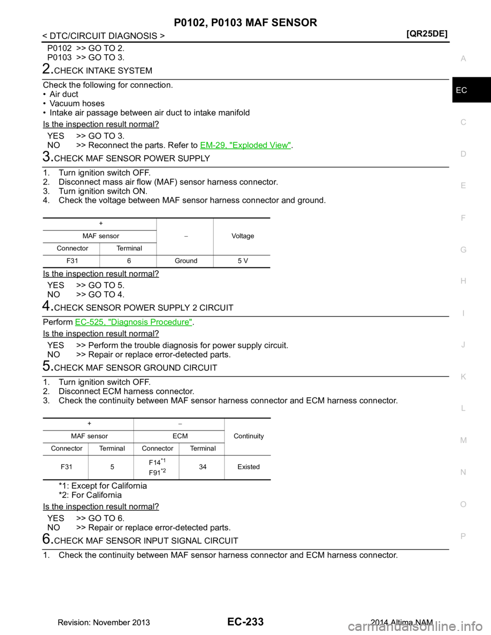
P0102, P0103 MAF SENSOREC-233
< DTC/CIRCUIT DIAGNOSIS > [QR25DE]
C
D E
F
G H
I
J
K L
M A
EC
NP
O
P0102 >> GO TO 2.
P0103 >> GO TO 3.
2.CHECK INTAKE SYSTEM
Check the following for connection.
• Air duct
• Vacuum hoses
• Intake air passage between air duct to intake manifold
Is the inspection result normal?
YES >> GO TO 3.
NO >> Reconnect the parts. Refer to EM-29, "Exploded View"
.
3.CHECK MAF SENSOR POWER SUPPLY
1. Turn ignition switch OFF.
2. Disconnect mass air flow (MAF) sensor harness connector.
3. Turn ignition switch ON.
4. Check the voltage between MAF sensor harness connector and ground.
Is the inspection result normal?
YES >> GO TO 5.
NO >> GO TO 4.
4.CHECK SENSOR POWER SUPPLY 2 CIRCUIT
Perform EC-525, "Diagnosis Procedure"
.
Is the inspection result normal?
YES >> Perform the trouble diagnosis for power supply circuit.
NO >> Repair or replace error-detected parts.
5.CHECK MAF SENSOR GROUND CIRCUIT
1. Turn ignition switch OFF.
2. Disconnect ECM harness connector.
3. Check the continuity between MAF sensor harness connector and ECM harness connector.
*1: Except for California
*2: For California
Is the inspection result normal?
YES >> GO TO 6.
NO >> Repair or replace error-detected parts.
6.CHECK MAF SENSOR INPUT SIGNAL CIRCUIT
1. Check the continuity between MAF sensor harness connector and ECM harness connector.
+
−Vo l ta g e
MAF sensor
Connector Terminal F31 6 Ground 5 V
+ −
Continuity
MAF sensor ECM
Connector Terminal Connector Terminal
F31 5 F14
*1
F91*234 Existed
Revision: November 20132014 Altima NAMRevision: November 20132014 Altima NAM