NISSAN TERRANO 2002 Service Repair Manual
Manufacturer: NISSAN, Model Year: 2002, Model line: TERRANO, Model: NISSAN TERRANO 2002Pages: 1767, PDF Size: 41.51 MB
Page 1261 of 1767
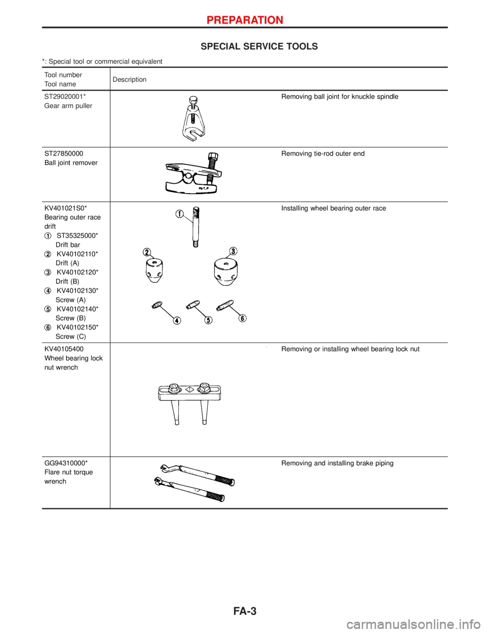
SPECIAL SERVICE TOOLS
*: Special tool or commercial equivalent
Tool number
Tool nameDescription
ST29020001*
Gear arm puller
Removing ball joint for knuckle spindle
ST27850000
Ball joint remover
Removing tie-rod outer end
KV401021S0*
Bearing outer race
drift
q
1ST35325000*
Drift bar
q
2KV40102110*
Drift (A)
q
3KV40102120*
Drift (B)
q
4KV40102130*
Screw (A)
q
5KV40102140*
Screw (B)
q
6KV40102150*
Screw (C)
Installing wheel bearing outer race
KV40105400
Wheel bearing lock
nut wrench
Removing or installing wheel bearing lock nut
GG94310000*
Flare nut torque
wrench
Removing and installing brake piping
PREPARATION
FA-3
Page 1262 of 1767

YFA003
FRONT AXLE AND FRONT SUSPENSION
FA-4
Page 1263 of 1767
Front Axle and Front Suspension Parts
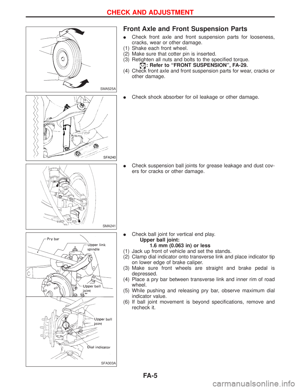
ICheck front axle and front suspension parts for looseness,
cracks, wear or other damage.
(1) Shake each front wheel.
(2) Make sure that cotter pin is inserted.
(3) Retighten all nuts and bolts to the specified torque.
: Refer to ªFRONT SUSPENSIONº, FA-29.
(4) Check front axle and front suspension parts for wear, cracks or
other damage.
ICheck shock absorber for oil leakage or other damage.
ICheck suspension ball joints for grease leakage and dust cov-
ers for cracks or other damage.
ICheck ball joint for vertical end play.
Upper ball joint:
1.6 mm (0.063 in) or less
(1) Jack up front of vehicle and set the stands.
(2) Clamp dial indicator onto transverse link and place indicator tip
on lower edge of brake caliper.
(3) Make sure front wheels are straight and brake pedal is
depressed.
(4) Place a pry bar between transverse link and inner rim of road
wheel.
(5) While pushing and releasing pry bar, observe maximum dial
indicator value.
(6) If ball joint movement is beyond specifications, remove and
recheck it.
SMA525A
SFA240
SMA241
SFA303A
CHECK AND ADJUSTMENT
FA-5
Page 1264 of 1767
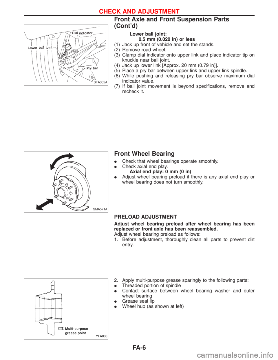
Lower ball joint:
0.5 mm (0.020 in) or less
(1) Jack up front of vehicle and set the stands.
(2) Remove road wheel.
(3) Clamp dial indicator onto upper link and place indicator tip on
knuckle near ball joint.
(4) Jack up lower link [Approx. 20 mm (0.79 in)].
(5) Place a pry bar between upper link and upper link spindle.
(6) While pushing and releasing pry bar observe maximum dial
indicator value.
(7) If ball joint movement is beyond specifications, remove and
recheck it.
Front Wheel Bearing
ICheck that wheel bearings operate smoothly.
ICheck axial end play.
Axial end play: 0 mm (0 in)
IAdjust wheel bearing preload if there is any axial end play or
wheel bearing does not turn smoothly.
PRELOAD ADJUSTMENT
Adjust wheel bearing preload after wheel bearing has been
replaced or front axle has been reassembled.
Adjust wheel bearing preload as follows:
1. Before adjustment, thoroughly clean all parts to prevent dirt
entry.
2. Apply multi-purpose grease sparingly to the following parts:
IThreaded portion of spindle
IContact surface between wheel bearing washer and outer
wheel bearing
IGrease seal lip
IWheel hub (as shown at left)
SFA302A
SMA571A
YFA008
CHECK AND ADJUSTMENT
Front Axle and Front Suspension Parts
(Cont'd)
FA-6
Page 1265 of 1767
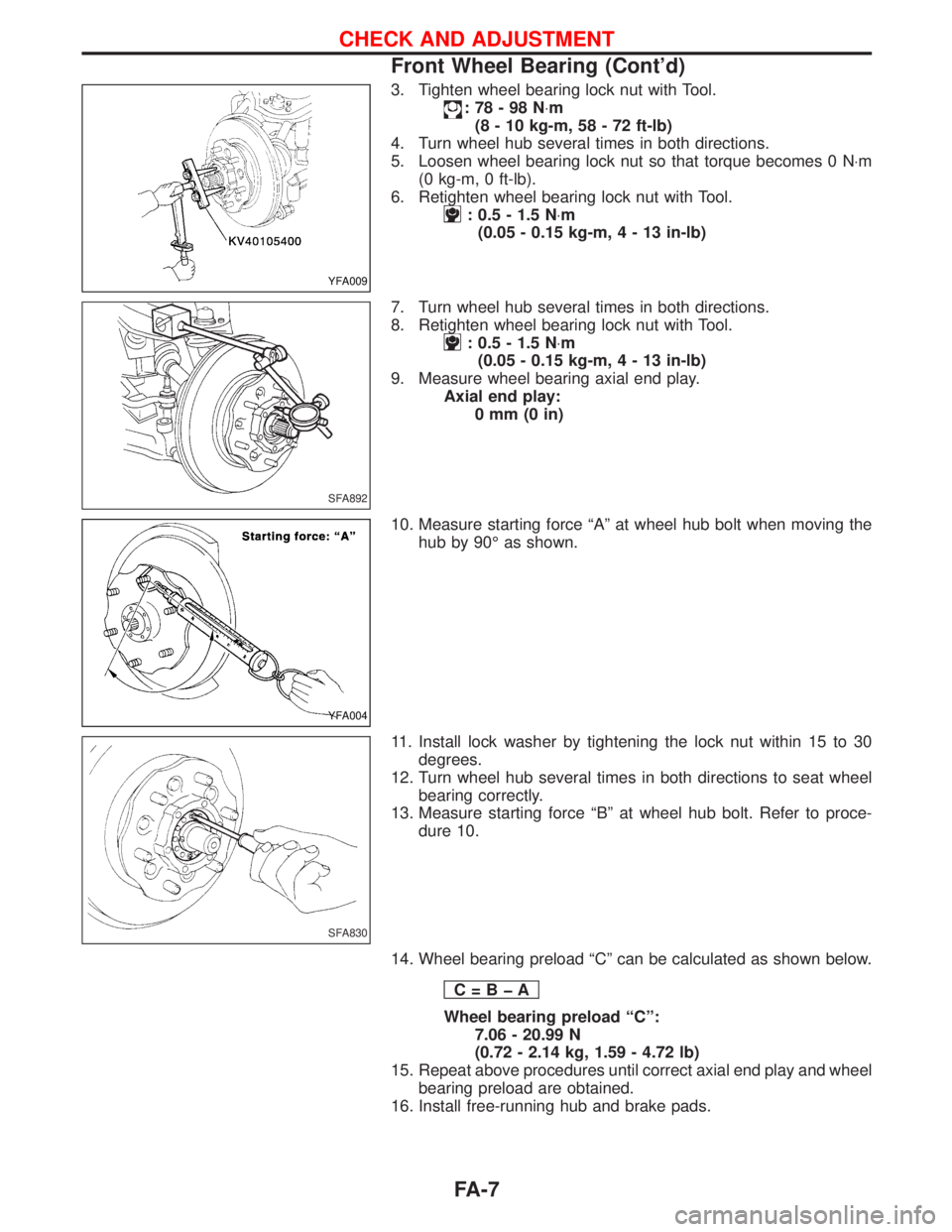
3. Tighten wheel bearing lock nut with Tool.
:78-98N×m
(8 - 10 kg-m, 58 - 72 ft-lb)
4. Turn wheel hub several times in both directions.
5. Loosen wheel bearing lock nut so that torque becomes 0 N×m
(0 kg-m, 0 ft-lb).
6. Retighten wheel bearing lock nut with Tool.
: 0.5 - 1.5 N×m
(0.05 - 0.15 kg-m,4-13in-lb)
7. Turn wheel hub several times in both directions.
8. Retighten wheel bearing lock nut with Tool.
: 0.5 - 1.5 N×m
(0.05 - 0.15 kg-m,4-13in-lb)
9. Measure wheel bearing axial end play.
Axial end play:
0mm(0in)
10. Measure starting force ªAº at wheel hub bolt when moving the
hub by 90É as shown.
11. Install lock washer by tightening the lock nut within 15 to 30
degrees.
12. Turn wheel hub several times in both directions to seat wheel
bearing correctly.
13. Measure starting force ªBº at wheel hub bolt. Refer to proce-
dure 10.
14. Wheel bearing preload ªCº can be calculated as shown below.
C=BþA
Wheel bearing preload ªCº:
7.06 - 20.99 N
(0.72 - 2.14 kg, 1.59 - 4.72 lb)
15. Repeat above procedures until correct axial end play and wheel
bearing preload are obtained.
16. Install free-running hub and brake pads.
YFA009
SFA892
YFA004
SFA830
CHECK AND ADJUSTMENT
Front Wheel Bearing (Cont'd)
FA-7
Page 1266 of 1767
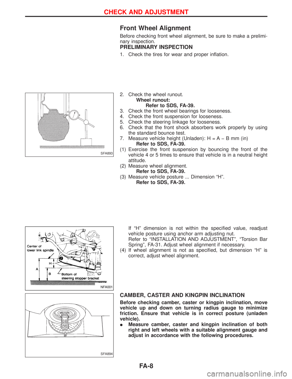
Front Wheel Alignment
Before checking front wheel alignment, be sure to make a prelimi-
nary inspection.
PRELIMINARY INSPECTION
1. Check the tires for wear and proper inflation.
2. Check the wheel runout.
Wheel runout:
Refer to SDS, FA-39.
3. Check the front wheel bearings for looseness.
4. Check the front suspension for looseness.
5. Check the steering linkage for looseness.
6. Check that the front shock absorbers work properly by using
the standard bounce test.
7. Measure vehicle height (Unladen): H = A þ B mm (in)
Refer to SDS, FA-39.
(1) Exercise the front suspension by bouncing the front of the
vehicle 4 or 5 times to ensure that vehicle is in a neutral height
attitude.
(2) Measure wheel alignment.
Refer to SDS, FA-39.
(3) Measure vehicle posture ... Dimension ªHº.
Refer to SDS, FA-39.
If ªHº dimension is not within the specified value, readjust
vehicle posture using anchor arm adjusting nut.
Refer to ªINSTALLATION AND ADJUSTMENTº, ªTorsion Bar
Springº, FA-31. Adjust wheel alignment if necessary.
(4) If wheel alignment is not as specified, but dimension ªHº is
correct, adjust wheel alignment.
CAMBER, CASTER AND KINGPIN INCLINATION
Before checking camber, caster or kingpin inclination, move
vehicle up and down on turning radius gauge to minimize
friction. Ensure that vehicle is in correct posture (unladen
vehicle).
IMeasure camber, caster and kingpin inclination of both
right and left wheels with a suitable alignment gauge and
adjust in accordance with the following procedures.
SFA893
NFA001
SFA894
CHECK AND ADJUSTMENT
FA-8
Page 1267 of 1767
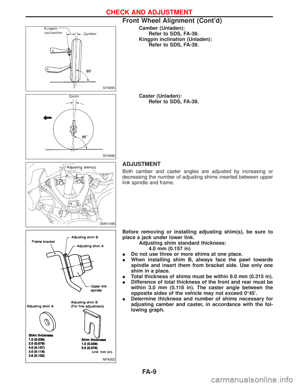
Camber (Unladen):
Refer to SDS, FA-39.
Kingpin inclination (Unladen):
Refer to SDS, FA-39.
Caster (Unladen):
Refer to SDS, FA-39.
ADJUSTMENT
Both camber and caster angles are adjusted by increasing or
decreasing the number of adjusting shims inserted between upper
link spindle and frame.
Before removing or installing adjusting shim(s), be sure to
place a jack under lower link.
Adjusting shim standard thickness:
4.0 mm (0.157 in)
IDo not use three or more shims at one place.
IWhen installing shim B, always face the pawl towards
spindle and insert them from bracket side. Use only one
shim in a place.
ITotal thickness of shims must be within 8.0 mm (0.315 in).
IDifference of total thickness of the front and rear must be
within 3.0 mm (0.118 in). The caster angle between the
opposite sides of the vehicle may not exceed 0É45¢.
IDetermine thickness and number of shims necessary for
adjusting camber and caster, in accordance with the fol-
lowing graph.
SFA895
SFA896
SMA144B
NFA002
CHECK AND ADJUSTMENT
Front Wheel Alignment (Cont'd)
FA-9
Page 1268 of 1767
![NISSAN TERRANO 2002 Service Repair Manual [Example]
(Measures taken at one side):
(1)
Angle
Specified value Measured Change
Camber angle 0É30¢0É5¢+0É25¢
Caster angle 1É54¢2É10¢þ0É16¢
The above values relate to the graph below:
Sh NISSAN TERRANO 2002 Service Repair Manual [Example]
(Measures taken at one side):
(1)
Angle
Specified value Measured Change
Camber angle 0É30¢0É5¢+0É25¢
Caster angle 1É54¢2É10¢þ0É16¢
The above values relate to the graph below:
Sh](/img/5/57393/w960_57393-1267.png)
[Example]
(Measures taken at one side):
(1)
Angle
Specified value Measured Change
Camber angle 0É30¢0É5¢+0É25¢
Caster angle 1É54¢2É10¢þ0É16¢
The above values relate to the graph below:
Shim thickness selection graph
(2) Obtain intersection point of lines in accordance with the graph.
Front: 1.4 mm
Rear: 2.0 mm
(3) Choose shims which are nearest to the values found in the
graph:
Front: 1.6 mm
Rear: 2.0 mm
(4) If shim thicknesses as calculated appear not to be available,
combinations of different shims should be used to meet the
desired total thickness of the shims.
EFA015
CHECK AND ADJUSTMENT
Front Wheel Alignment (Cont'd)
FA-10
Page 1269 of 1767
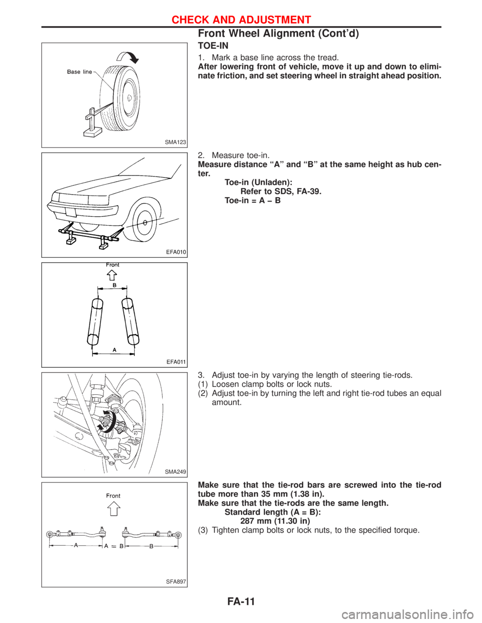
TOE-IN
1. Mark a base line across the tread.
After lowering front of vehicle, move it up and down to elimi-
nate friction, and set steering wheel in straight ahead position.
2. Measure toe-in.
Measure distance ªAº and ªBº at the same height as hub cen-
ter.
Toe-in (Unladen):
Refer to SDS, FA-39.
Toe-in = A þ B
3. Adjust toe-in by varying the length of steering tie-rods.
(1) Loosen clamp bolts or lock nuts.
(2) Adjust toe-in by turning the left and right tie-rod tubes an equal
amount.
Make sure that the tie-rod bars are screwed into the tie-rod
tube more than 35 mm (1.38 in).
Make sure that the tie-rods are the same length.
Standard length (A = B):
287 mm (11.30 in)
(3) Tighten clamp bolts or lock nuts, to the specified torque.
SMA123
EFA010
EFA011
SMA249
SFA897
CHECK AND ADJUSTMENT
Front Wheel Alignment (Cont'd)
FA-11
Page 1270 of 1767
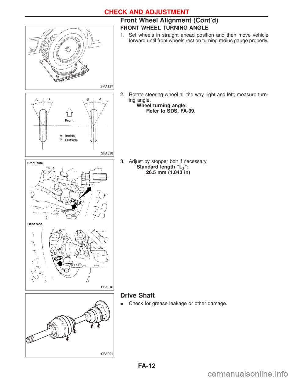
FRONT WHEEL TURNING ANGLE
1. Set wheels in straight ahead position and then move vehicle
forward until front wheels rest on turning radius gauge properly.
2. Rotate steering wheel all the way right and left; measure turn-
ing angle.
Wheel turning angle:
Refer to SDS, FA-39.
3. Adjust by stopper bolt if necessary.
Standard length ªL
2º:
26.5 mm (1.043 in)
Drive Shaft
ICheck for grease leakage or other damage.
SMA127
SFA898
EFA016
SFA901
CHECK AND ADJUSTMENT
Front Wheel Alignment (Cont'd)
FA-12