NISSAN TERRANO 2002 Service Repair Manual
TERRANO 2002
NISSAN
NISSAN
https://www.carmanualsonline.info/img/5/57393/w960_57393-0.png
NISSAN TERRANO 2002 Service Repair Manual
Trending: battery replacement, airbag, low oil pressure, clock, Start, change wheel, fuel cap release
Page 1301 of 1767
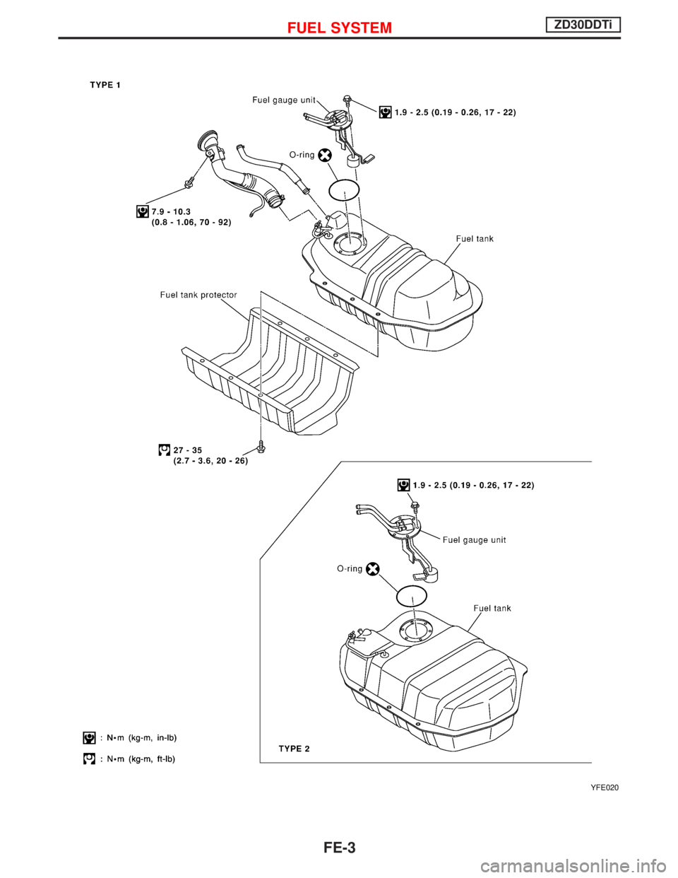
YFE020
FUEL SYSTEMZD30DDTi
FE-3
Page 1302 of 1767
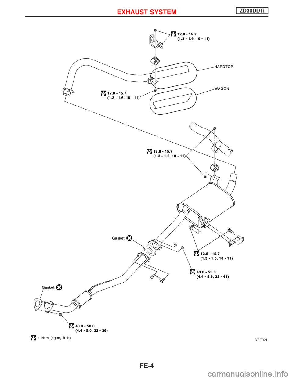
YFE021
EXHAUST SYSTEMZD30DDTi
FE-4
Page 1303 of 1767
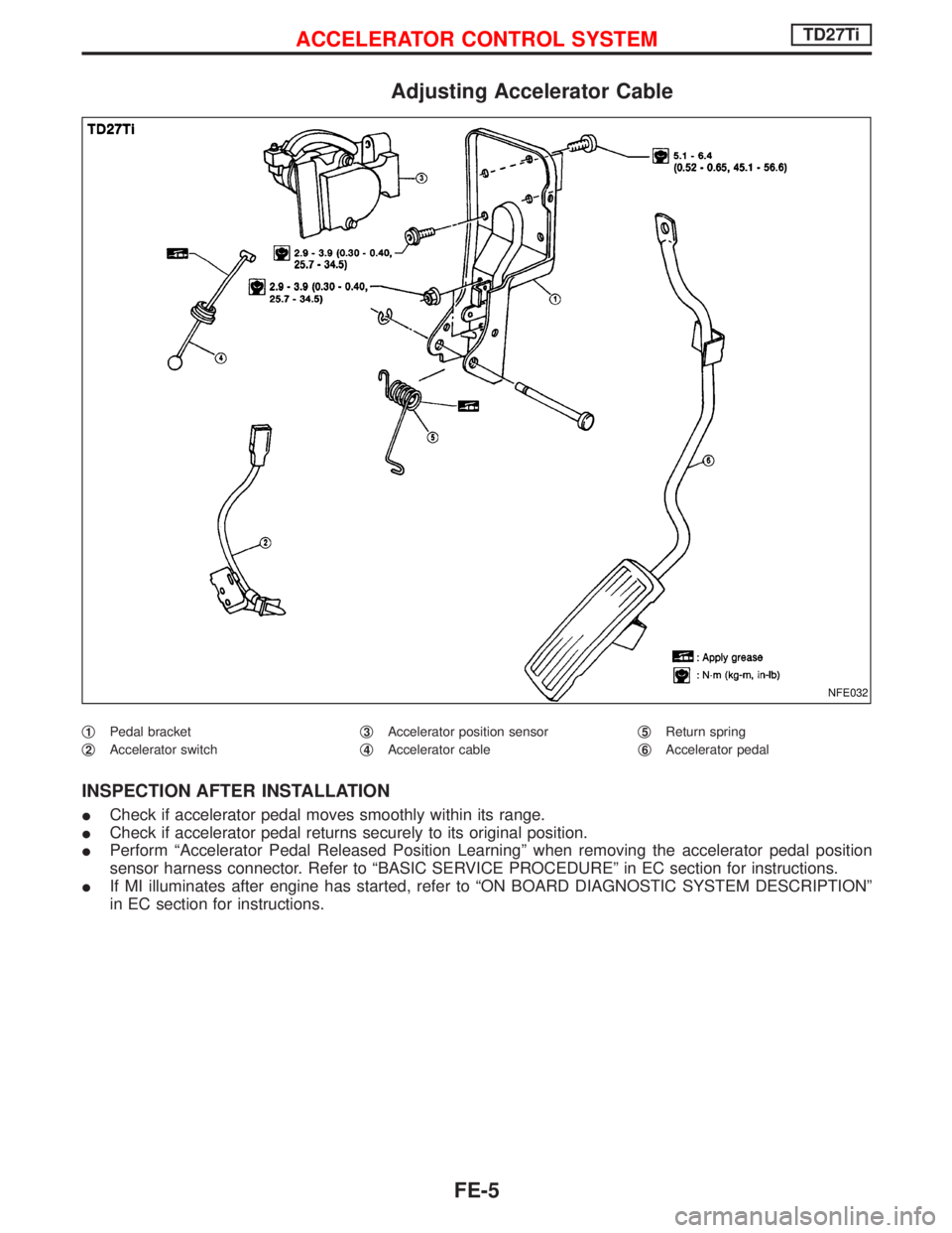
Adjusting Accelerator Cable
q1Pedal bracket
q
2Accelerator switchq
3Accelerator position sensor
q
4Accelerator cableq
5Return spring
q
6Accelerator pedal
INSPECTION AFTER INSTALLATION
ICheck if accelerator pedal moves smoothly within its range.
ICheck if accelerator pedal returns securely to its original position.
IPerform ªAccelerator Pedal Released Position Learningº when removing the accelerator pedal position
sensor harness connector. Refer to ªBASIC SERVICE PROCEDUREº in EC section for instructions.
IIf MI illuminates after engine has started, refer to ªON BOARD DIAGNOSTIC SYSTEM DESCRIPTIONº
in EC section for instructions.
NFE032
ACCELERATOR CONTROL SYSTEMTD27Ti
FE-5
Page 1304 of 1767
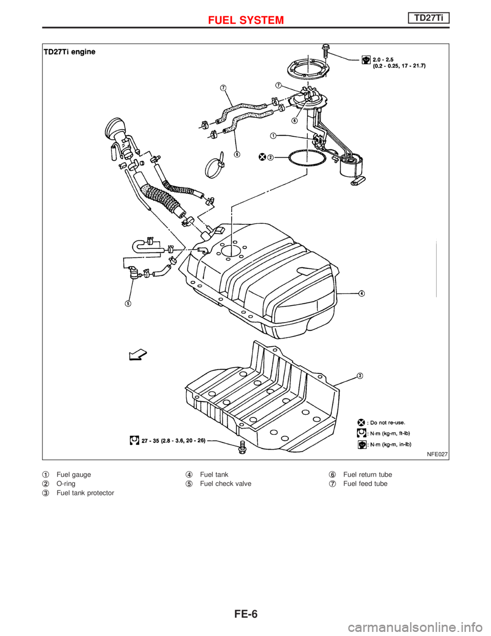
q1Fuel gauge
q
2O-ring
q
3Fuel tank protectorq
4Fuel tank
q
5Fuel check valveq
6Fuel return tube
q
7Fuel feed tube
NFE027
FUEL SYSTEMTD27Ti
FE-6
Page 1305 of 1767
WARNING:
When replacing fuel line parts, be sure to observe the following:
IDisplay a ªCAUTION:INFLAMMABLEº sign in workshop.
IBe sure to furnish workshop with a CO
2fire extinguisher service.
IDo not smoke while servicing fuel system. Keep open flames and sparks away from work area.
IBe sure to disconnect battery ground cable before conducting operations.
IPour drained fuel into an explosion-proof container, then ensure container lid is installed securely.
CAUTION:
IFor ECM models, release fuel pressure from fuel line. Refer to EC section (ªFuel Pressure Releaseº,
ªBASIC SERVICE PROCEDUREº).
IDo not disconnect any fuel line unless absolutely necessary.
IPlug hose and pipe openings to prevent entry of dust or dirt.
IAlways replace top lid seal and hose clamps with new ones.
IDo not kink or twist hoses and tubes during installation.
IDo not tighten hose clamps excessively because this could cause damage to the hose.
IEnsure fuel check valve is installed in the correct orientation.
IRefer to EC section (ªFUEL CHECK VALVEº, ªEVAPORATIVE EMISSION SYSTEMº).
IAfter installation, run engine and check for fuel leaks at connections.
Fuel Pump and Gauge
REMOVAL
Petrol engine
1. Release fuel pressure from fuel line.
Refer to EC section (ªFuel Pressure Releaseº, ªBASIC SER-
VICE PROCEDUREº).
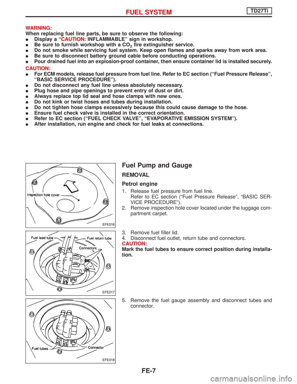
2. Remove inspection hole cover located under the luggage com-
partment carpet.
3. Remove fuel filler lid.
4. Disconnect fuel outlet, return tube and connectors.
CAUTION:
Mark the fuel tubes to ensure correct position during installa-
tion.
5. Remove the fuel gauge assembly and disconnect tubes and
connector.
EFE016
EFE017
EFE018
FUEL SYSTEMTD27Ti
FE-7
Page 1306 of 1767
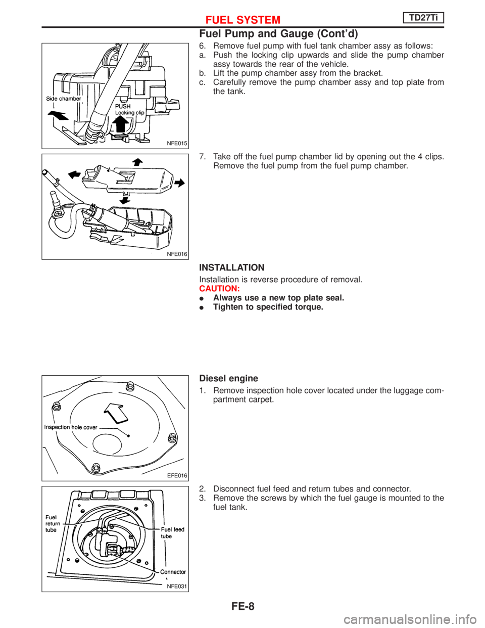
6. Remove fuel pump with fuel tank chamber assy as follows:
a. Push the locking clip upwards and slide the pump chamber
assy towards the rear of the vehicle.
b. Lift the pump chamber assy from the bracket.
c. Carefully remove the pump chamber assy and top plate from
the tank.
7. Take off the fuel pump chamber lid by opening out the 4 clips.
Remove the fuel pump from the fuel pump chamber.
INSTALLATION
Installation is reverse procedure of removal.
CAUTION:
IAlways use a new top plate seal.
ITighten to specified torque.
Diesel engine
1. Remove inspection hole cover located under the luggage com-
partment carpet.
2. Disconnect fuel feed and return tubes and connector.
3. Remove the screws by which the fuel gauge is mounted to the
fuel tank.
NFE015
NFE016
EFE016
NFE031
FUEL SYSTEMTD27Ti
Fuel Pump and Gauge (Cont'd)
FE-8
Page 1307 of 1767
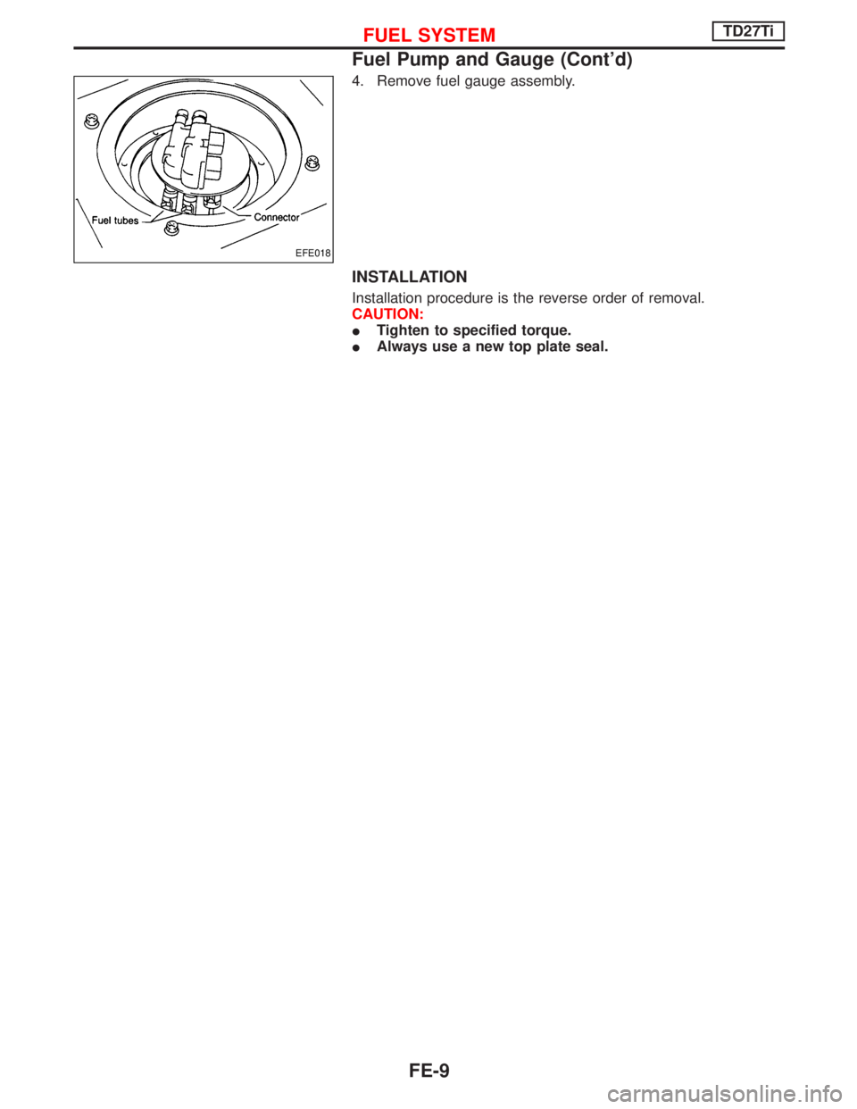
4. Remove fuel gauge assembly.
INSTALLATION
Installation procedure is the reverse order of removal.
CAUTION:
ITighten to specified torque.
IAlways use a new top plate seal.
EFE018
FUEL SYSTEMTD27Ti
Fuel Pump and Gauge (Cont'd)
FE-9
Page 1308 of 1767
CAUTION:
IBe careful not to drop or damage catalytic converter.
INever wet catalytic converter with water, oil, etc.
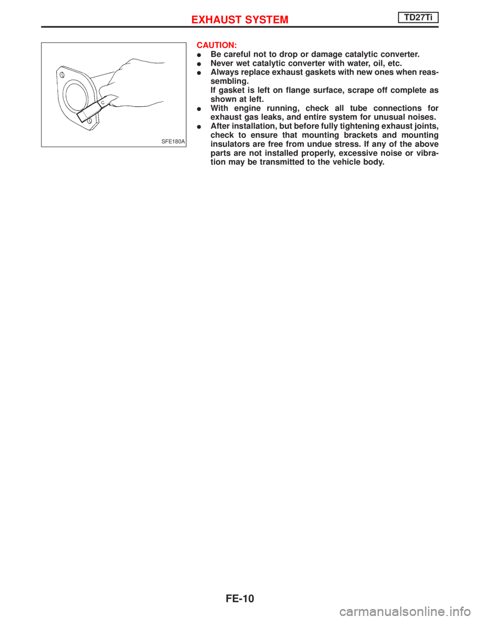
IAlways replace exhaust gaskets with new ones when reas-
sembling.
If gasket is left on flange surface, scrape off complete as
shown at left.
IWith engine running, check all tube connections for
exhaust gas leaks, and entire system for unusual noises.
IAfter installation, but before fully tightening exhaust joints,
check to ensure that mounting brackets and mounting
insulators are free from undue stress. If any of the above
parts are not installed properly, excessive noise or vibra-
tion may be transmitted to the vehicle body.
SFE180A
EXHAUST SYSTEMTD27Ti
FE-10
Page 1309 of 1767
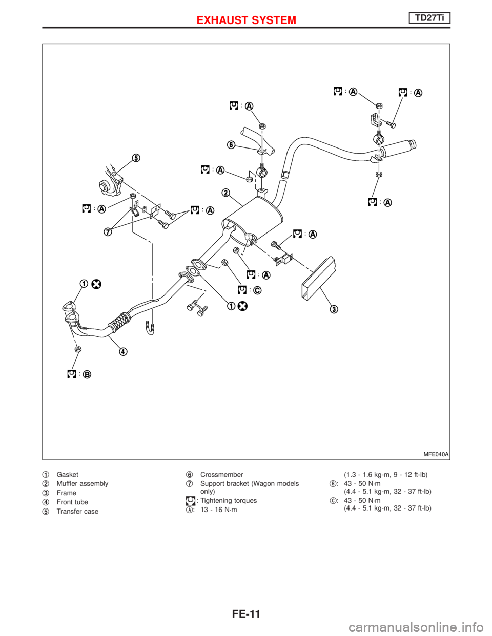
q1Gasket
q
2Muffler assembly
q
3Frame
q
4Front tube
q
5Transfer caseq
6Crossmember
q
7Support bracket (Wagon models
only)
: Tightening torques
q
A: 13-16N×m(1.3 - 1.6 kg-m,9-12ft-lb)
q
B: 43-50N×m
(4.4 - 5.1 kg-m, 32 - 37 ft-lb)
q
C: 43-50N×m
(4.4 - 5.1 kg-m, 32 - 37 ft-lb)
MFE040A
EXHAUST SYSTEMTD27Ti
FE-11
Page 1310 of 1767
Trending: engine oil, immobilizer, spare wheel, fuse box, cooling, headrest, service indicator
