NISSAN TERRANO 2002 Service Repair Manual
TERRANO 2002
NISSAN
NISSAN
https://www.carmanualsonline.info/img/5/57393/w960_57393-0.png
NISSAN TERRANO 2002 Service Repair Manual
Trending: Condition, VEHICLE INFORMATION, radio controls, steering wheel adjustment, differential, lighting system, gearbox
Page 1221 of 1767
Assembly
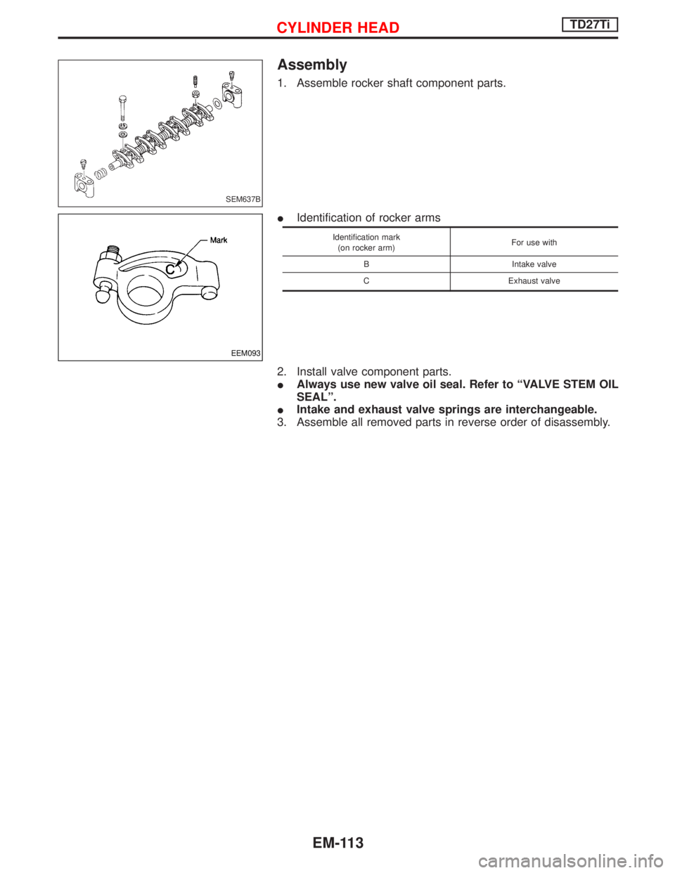
1. Assemble rocker shaft component parts.
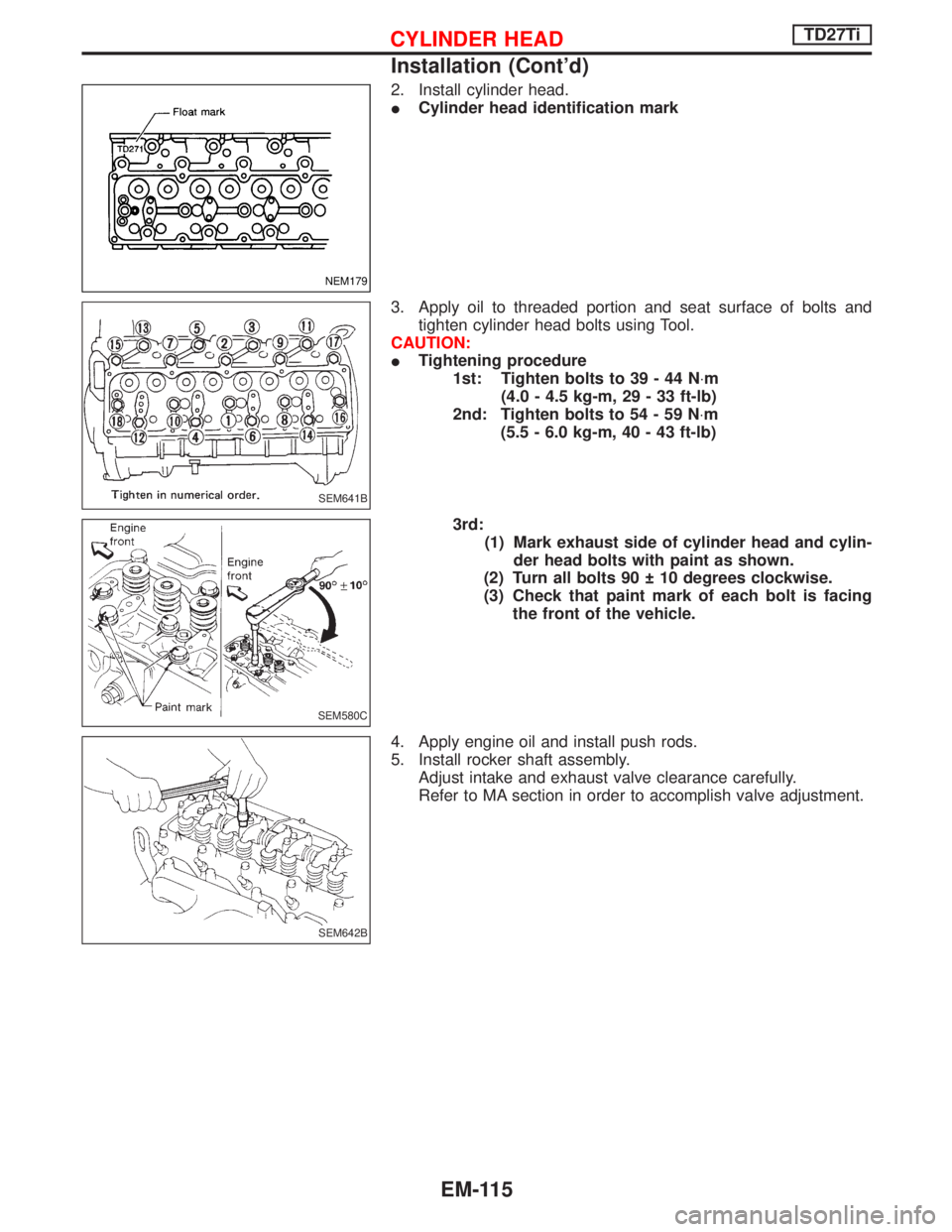
IIdentification of rocker arms
Identification mark
(on rocker arm)For use with
B Intake valve
C Exhaust valve
2. Install valve component parts.
IAlways use new valve oil seal. Refer to ªVALVE STEM OIL
SEALº.
IIntake and exhaust valve springs are interchangeable.
3. Assemble all removed parts in reverse order of disassembly.
SEM637B
EEM093
CYLINDER HEADTD27Ti
EM-113
Page 1222 of 1767
Installation
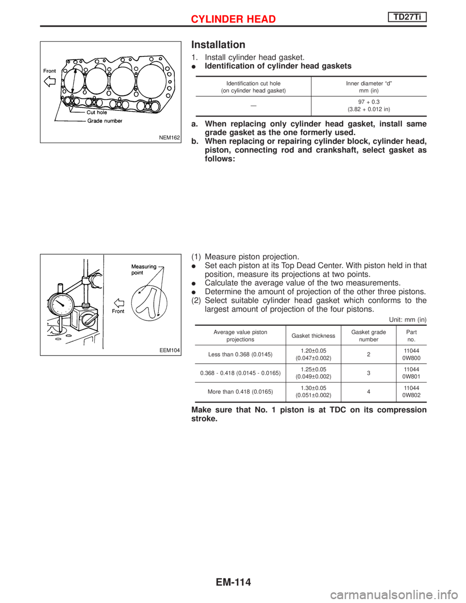
1. Install cylinder head gasket.
IIdentification of cylinder head gaskets
Identification cut hole
(on cylinder head gasket)Inner diameter ªdº
mm (in)
Ð97 + 0.3
(3.82 + 0.012 in)
a. When replacing only cylinder head gasket, install same
grade gasket as the one formerly used.
b. When replacing or repairing cylinder block, cylinder head,
piston, connecting rod and crankshaft, select gasket as
follows:
(1) Measure piston projection.
ISet each piston at its Top Dead Center. With piston held in that
position, measure its projections at two points.
ICalculate the average value of the two measurements.
IDetermine the amount of projection of the other three pistons.
(2) Select suitable cylinder head gasket which conforms to the
largest amount of projection of the four pistons.
Unit: mm (in)
Average value piston
projectionsGasket thicknessGasket grade
numberPart
no.
Less than 0.368 (0.0145)1.20 0.05
(0.047 0.002)211044
0W800
0.368 - 0.418 (0.0145 - 0.0165)1.25 0.05
(0.049 0.002)311044
0W801
More than 0.418 (0.0165)1.30 0.05
(0.051 0.002)411044
0W802
Make sure that No. 1 piston is at TDC on its compression
stroke.
NEM162
EEM104
CYLINDER HEADTD27Ti
EM-114
Page 1223 of 1767
2. Install cylinder head.
ICylinder head identification mark
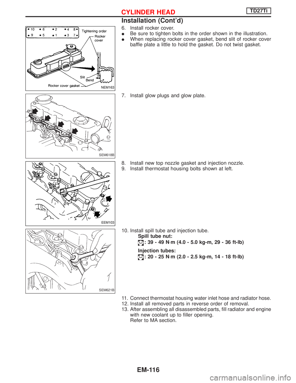
3. Apply oil to threaded portion and seat surface of bolts and
tighten cylinder head bolts using Tool.
CAUTION:
ITightening procedure
1st: Tighten bolts to 39 - 44 N×m
(4.0 - 4.5 kg-m, 29 - 33 ft-lb)
2nd: Tighten bolts to 54 - 59 N×m
(5.5 - 6.0 kg-m, 40 - 43 ft-lb)
3rd:
(1) Mark exhaust side of cylinder head and cylin-
der head bolts with paint as shown.
(2) Turn all bolts 90 10 degrees clockwise.
(3) Check that paint mark of each bolt is facing
the front of the vehicle.
4. Apply engine oil and install push rods.
5. Install rocker shaft assembly.
Adjust intake and exhaust valve clearance carefully.
Refer to MA section in order to accomplish valve adjustment.
NEM179
SEM641B
SEM580C
SEM642B
CYLINDER HEADTD27Ti
Installation (Cont'd)
EM-115
Page 1224 of 1767
6. Install rocker cover.
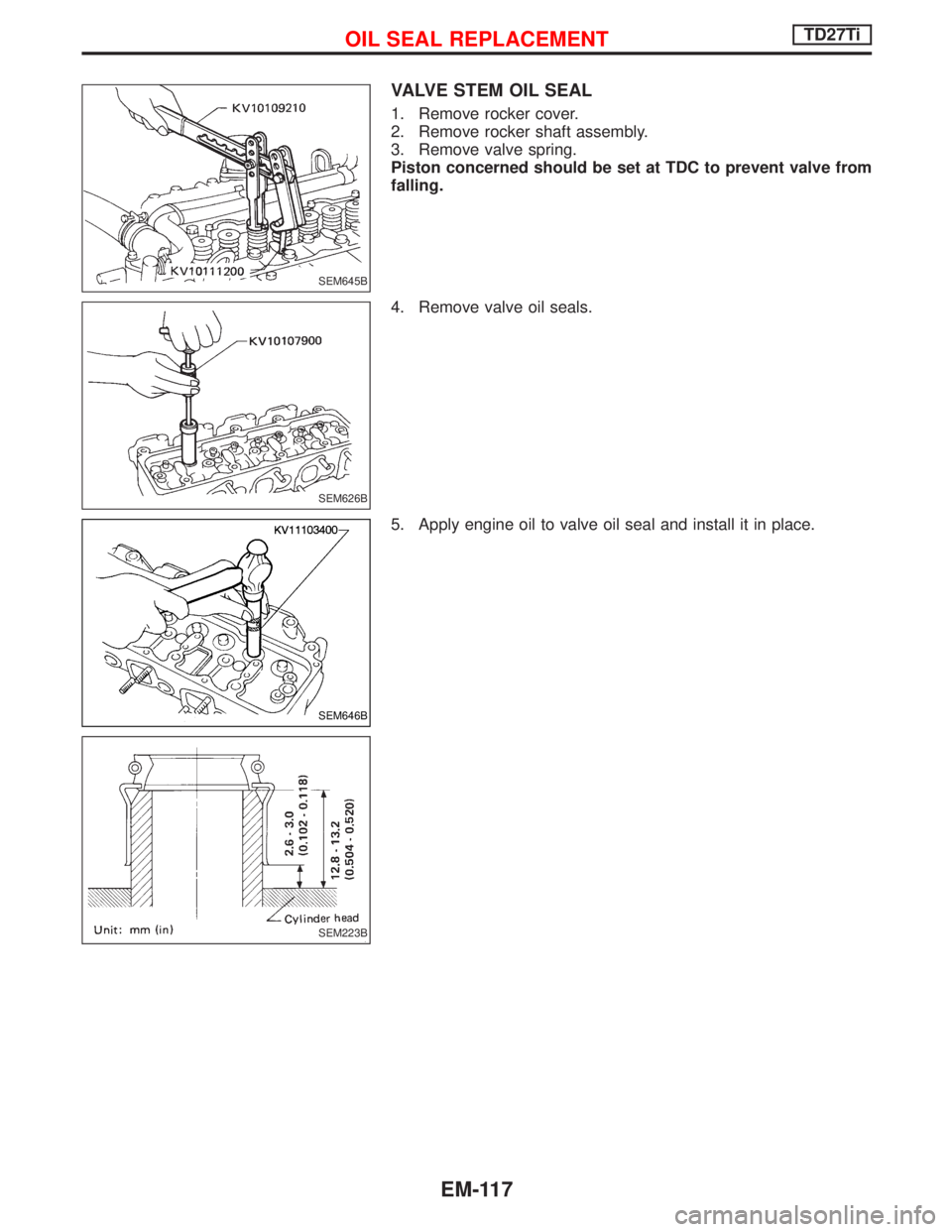
IBe sure to tighten bolts in the order shown in the illustration.
IWhen replacing rocker cover gasket, bend slit of rocker cover
baffle plate a little to hold the gasket. Do not twist gasket.
7. Install glow plugs and glow plate.
8. Install new top nozzle gasket and injection nozzle.
9. Install thermostat housing bolts shown at left.
10. Install spill tube and injection tube.
Spill tube nut:
:39-49N×m (4.0 - 5.0 kg-m, 29 - 36 ft-lb)
Injection tubes:
:20-25N×m (2.0 - 2.5 kg-m, 14 - 18 ft-lb)
11. Connect thermostat housing water inlet hose and radiator hose.
12. Install all removed parts in reverse order of removal.
13. After assembling all disassembled parts, fill radiator and engine
with new coolant up to filler opening.
Refer to MA section.
NEM163
SEM618B
EEM103
SEM621B
CYLINDER HEADTD27Ti
Installation (Cont'd)
EM-116
Page 1225 of 1767
VALVE STEM OIL SEAL
1. Remove rocker cover.
2. Remove rocker shaft assembly.
3. Remove valve spring.
Piston concerned should be set at TDC to prevent valve from
falling.
4. Remove valve oil seals.
5. Apply engine oil to valve oil seal and install it in place.
SEM645B
SEM626B
SEM646B
SEM223B
OIL SEAL REPLACEMENTTD27Ti
EM-117
Page 1226 of 1767
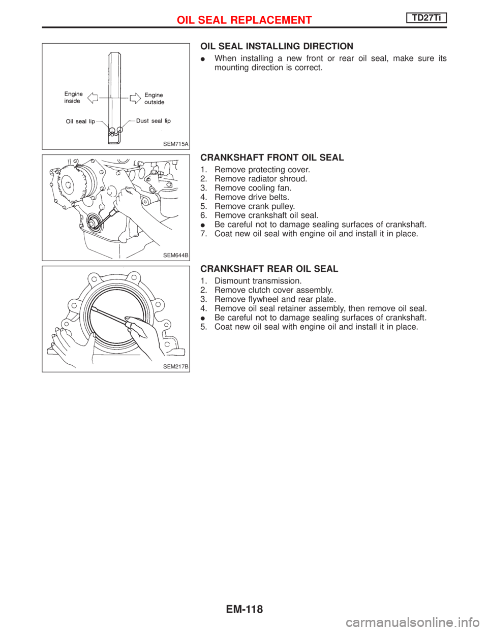
OIL SEAL INSTALLING DIRECTION
IWhen installing a new front or rear oil seal, make sure its
mounting direction is correct.
CRANKSHAFT FRONT OIL SEAL
1. Remove protecting cover.
2. Remove radiator shroud.
3. Remove cooling fan.
4. Remove drive belts.
5. Remove crank pulley.
6. Remove crankshaft oil seal.
IBe careful not to damage sealing surfaces of crankshaft.
7. Coat new oil seal with engine oil and install it in place.
CRANKSHAFT REAR OIL SEAL
1. Dismount transmission.
2. Remove clutch cover assembly.
3. Remove flywheel and rear plate.
4. Remove oil seal retainer assembly, then remove oil seal.
IBe careful not to damage sealing surfaces of crankshaft.
5. Coat new oil seal with engine oil and install it in place.
SEM715A
SEM644B
SEM217B
OIL SEAL REPLACEMENTTD27Ti
EM-118
Page 1227 of 1767
Removal and Installation
Turbocharger should not be disassembled.
1. Drain engine coolant.
2. Remove the following:
IAir duct and intercooler components
IHeat shield plates
IExhaust front tube
IOil tubes
IWater tubes
3. Remove turbocharger from exhaust manifold.
4. Remove turbocharger bracket bolts.
Inspection
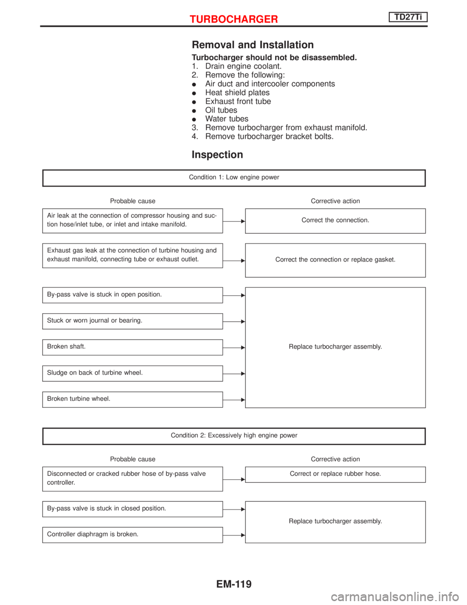
Condition 1: Low engine power
Probable cause Corrective action
Air leak at the connection of compressor housing and suc-
tion hose/inlet tube, or inlet and intake manifold.
ECorrect the connection.
Exhaust gas leak at the connection of turbine housing and
exhaust manifold, connecting tube or exhaust outlet.
ECorrect the connection or replace gasket.
By-pass valve is stuck in open position.E
Replace turbocharger assembly.
Stuck or worn journal or bearing.E
Broken shaft.E
Sludge on back of turbine wheel.E
Broken turbine wheel.E
Condition 2: Excessively high engine power
Probable cause Corrective action
Disconnected or cracked rubber hose of by-pass valve
controller.
ECorrect or replace rubber hose.
By-pass valve is stuck in closed position.E
Replace turbocharger assembly.
Controller diaphragm is broken.E
TURBOCHARGERTD27Ti
EM-119
Page 1228 of 1767
Condition 3: Excessively high oil consumption, or exhaust shows pale blue smoke
Probable cause Corrective action
Oil leak at the connection of lubricating oil passage.
ECorrect the connection.
Oil leak at oil seal of turbine.E
Replace turbocharger assembly.Oil leak at oil seal of compressor.E
Worn journal or bearing.E
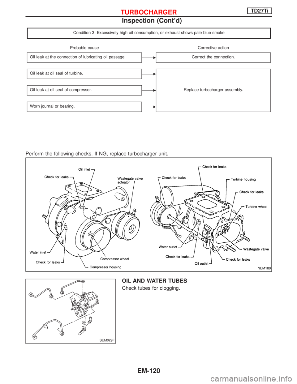
Perform the following checks. If NG, replace turbocharger unit.
OIL AND WATER TUBES
Check tubes for clogging.
NEM180
SEM029F
TURBOCHARGERTD27Ti
Inspection (Cont'd)
EM-120
Page 1229 of 1767
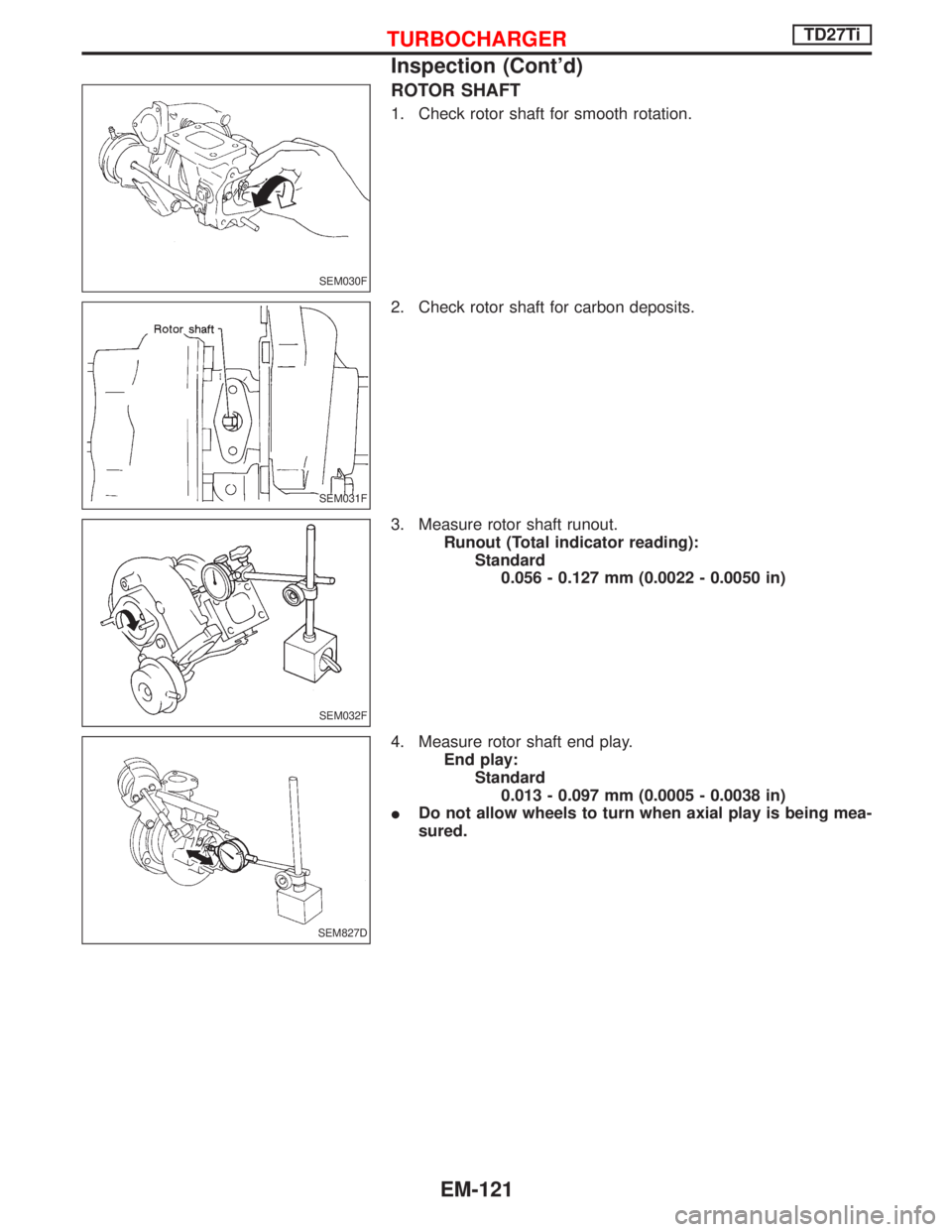
ROTOR SHAFT
1. Check rotor shaft for smooth rotation.
2. Check rotor shaft for carbon deposits.
3. Measure rotor shaft runout.
Runout (Total indicator reading):
Standard
0.056 - 0.127 mm (0.0022 - 0.0050 in)
4. Measure rotor shaft end play.
End play:
Standard
0.013 - 0.097 mm (0.0005 - 0.0038 in)
IDo not allow wheels to turn when axial play is being mea-
sured.
SEM030F
SEM031F
SEM032F
SEM827D
TURBOCHARGERTD27Ti
Inspection (Cont'd)
EM-121
Page 1230 of 1767
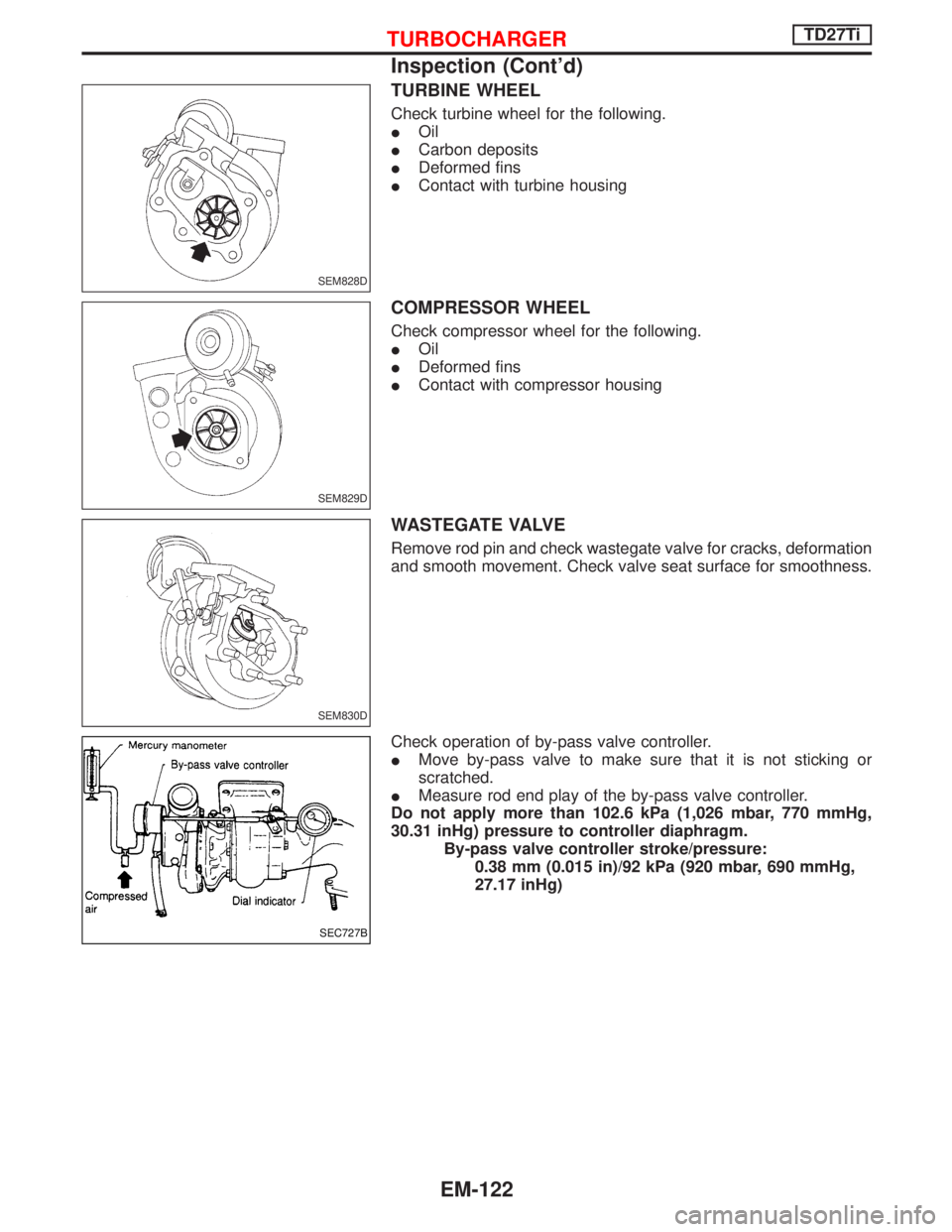
TURBINE WHEEL
Check turbine wheel for the following.
IOil
ICarbon deposits
IDeformed fins
IContact with turbine housing
COMPRESSOR WHEEL
Check compressor wheel for the following.
IOil
IDeformed fins
IContact with compressor housing
WASTEGATE VALVE
Remove rod pin and check wastegate valve for cracks, deformation
and smooth movement. Check valve seat surface for smoothness.
Check operation of by-pass valve controller.
IMove by-pass valve to make sure that it is not sticking or
scratched.
IMeasure rod end play of the by-pass valve controller.
Do not apply more than 102.6 kPa (1,026 mbar, 770 mmHg,
30.31 inHg) pressure to controller diaphragm.
By-pass valve controller stroke/pressure:
0.38 mm (0.015 in)/92 kPa (920 mbar, 690 mmHg,
27.17 inHg)
SEM828D
SEM829D
SEM830D
SEC727B
TURBOCHARGERTD27Ti
Inspection (Cont'd)
EM-122
Trending: brake rotor, height, tire size, drain bolt, warning light, immobilizer, open hood
