NISSAN TERRANO 2002 Service Repair Manual
TERRANO 2002
NISSAN
NISSAN
https://www.carmanualsonline.info/img/5/57393/w960_57393-0.png
NISSAN TERRANO 2002 Service Repair Manual
Trending: washer fluid, ECU, alternator replacement, g sensor, battery location, power steering, IDENTIFICATION INFORMATION
Page 1611 of 1767
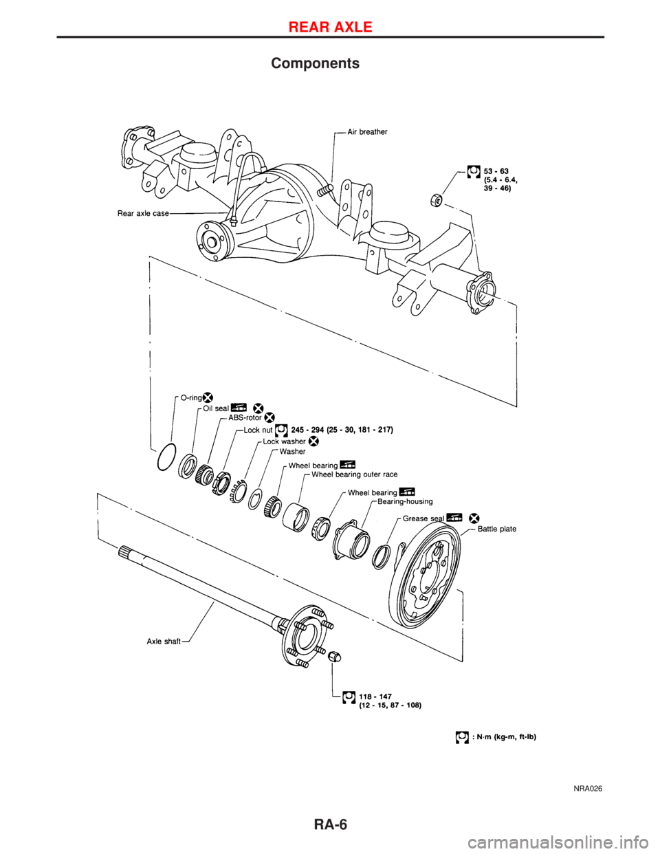
Components
NRA026
REAR AXLE
RA-6
Page 1612 of 1767
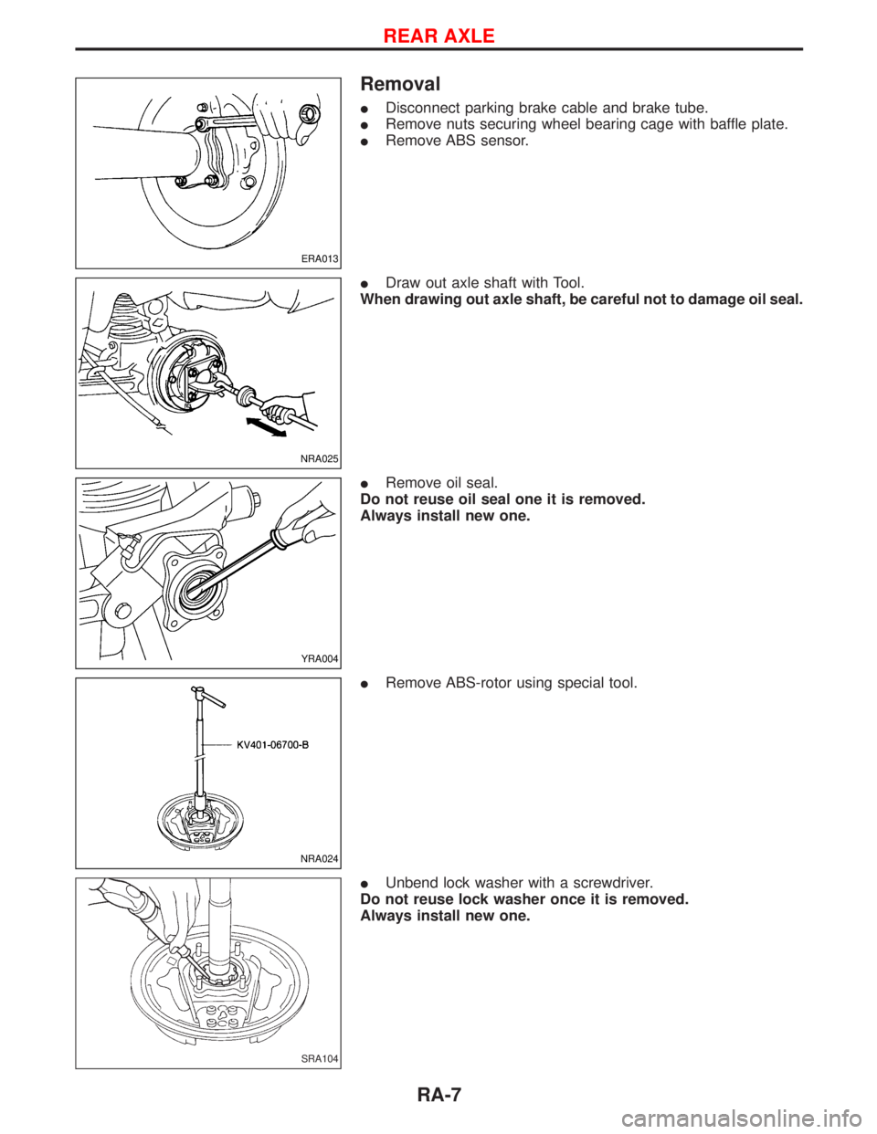
Removal
IDisconnect parking brake cable and brake tube.
IRemove nuts securing wheel bearing cage with baffle plate.
IRemove ABS sensor.
IDraw out axle shaft with Tool.
When drawing out axle shaft, be careful not to damage oil seal.
IRemove oil seal.
Do not reuse oil seal one it is removed.
Always install new one.
IRemove ABS-rotor using special tool.
IUnbend lock washer with a screwdriver.
Do not reuse lock washer once it is removed.
Always install new one.
ERA013
NRA025
YRA004
NRA024
SRA104
REAR AXLE
RA-7
Page 1613 of 1767
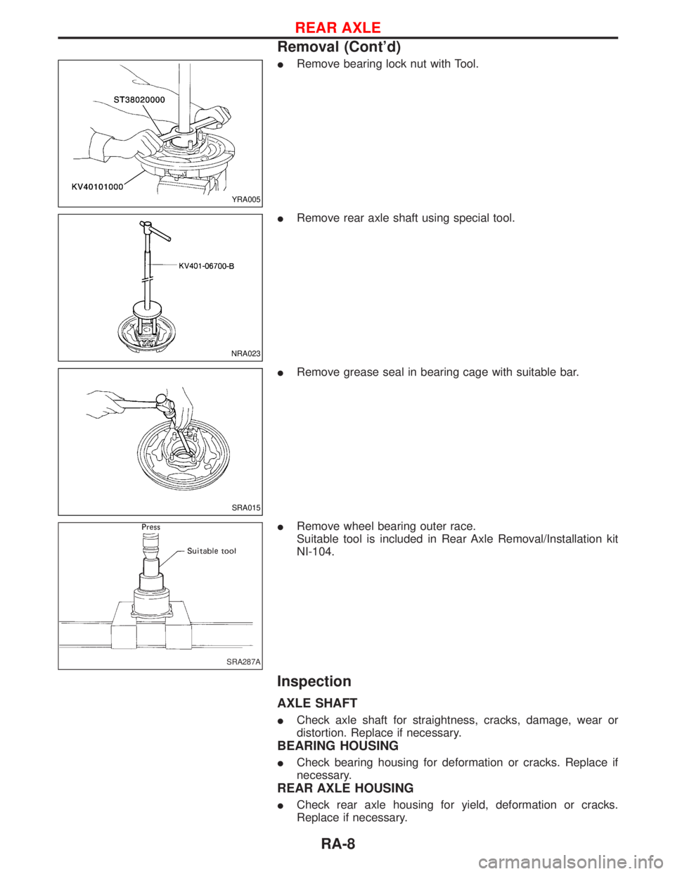
IRemove bearing lock nut with Tool.
IRemove rear axle shaft using special tool.
IRemove grease seal in bearing cage with suitable bar.
IRemove wheel bearing outer race.
Suitable tool is included in Rear Axle Removal/Installation kit
NI-104.
Inspection
AXLE SHAFT
ICheck axle shaft for straightness, cracks, damage, wear or
distortion. Replace if necessary.
BEARING HOUSING
ICheck bearing housing for deformation or cracks. Replace if
necessary.
REAR AXLE HOUSING
ICheck rear axle housing for yield, deformation or cracks.
Replace if necessary.
YRA005
NRA023
SRA015
SRA287A
REAR AXLE
Removal (Cont'd)
RA-8
Page 1614 of 1767
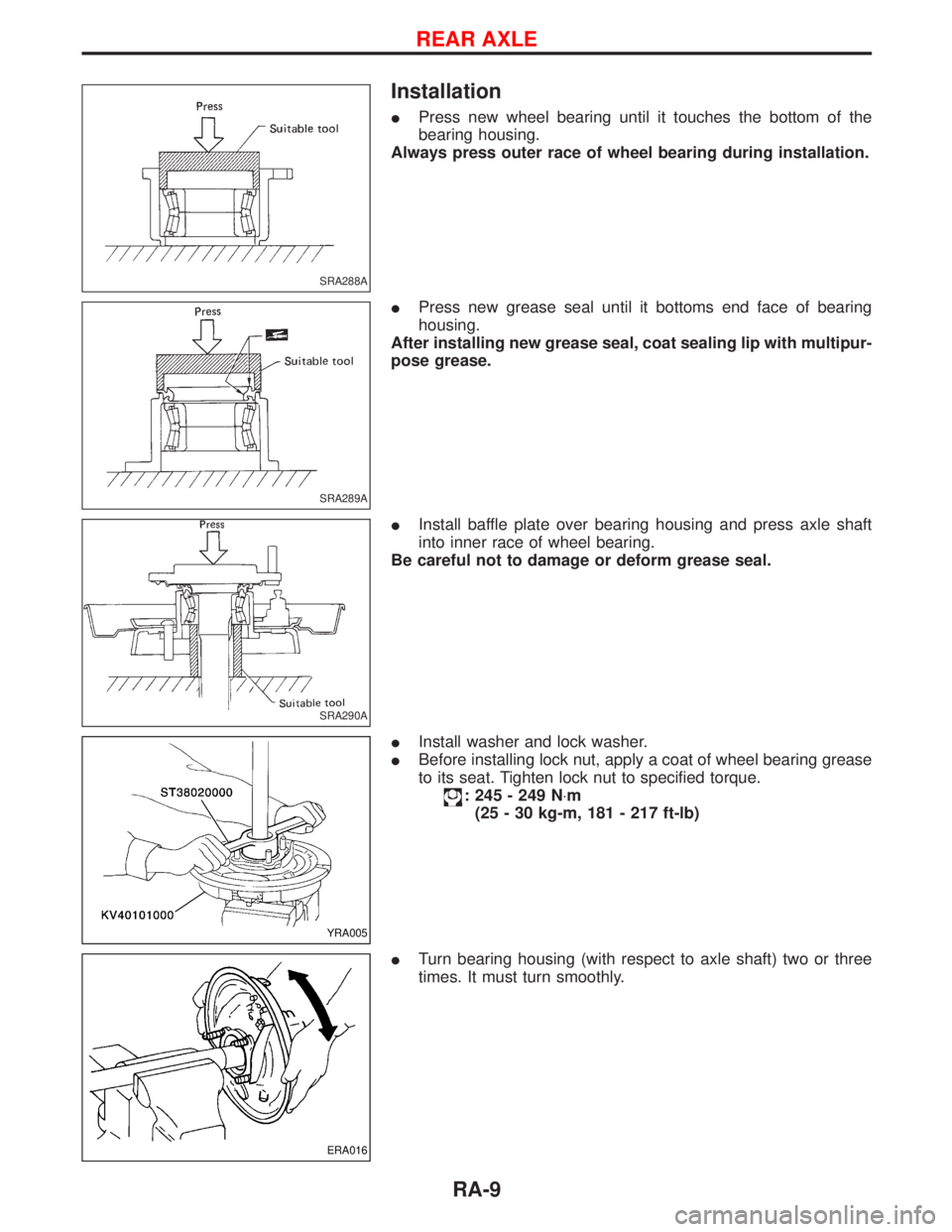
Installation
IPress new wheel bearing until it touches the bottom of the
bearing housing.
Always press outer race of wheel bearing during installation.
IPress new grease seal until it bottoms end face of bearing
housing.
After installing new grease seal, coat sealing lip with multipur-
pose grease.
IInstall baffle plate over bearing housing and press axle shaft
into inner race of wheel bearing.
Be careful not to damage or deform grease seal.
IInstall washer and lock washer.
IBefore installing lock nut, apply a coat of wheel bearing grease
to its seat. Tighten lock nut to specified torque.
: 245 - 249 N×m
(25 - 30 kg-m, 181 - 217 ft-lb)
ITurn bearing housing (with respect to axle shaft) two or three
times. It must turn smoothly.
SRA288A
SRA289A
SRA290A
YRA005
ERA016
REAR AXLE
RA-9
Page 1615 of 1767
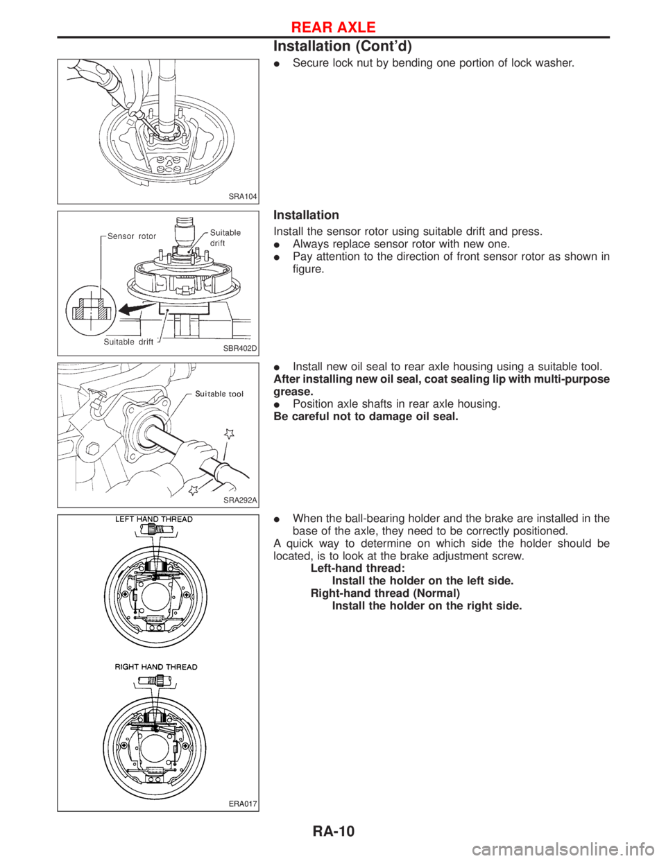
ISecure lock nut by bending one portion of lock washer.
Installation
Install the sensor rotor using suitable drift and press.
IAlways replace sensor rotor with new one.
IPay attention to the direction of front sensor rotor as shown in
figure.
IInstall new oil seal to rear axle housing using a suitable tool.
After installing new oil seal, coat sealing lip with multi-purpose
grease.
IPosition axle shafts in rear axle housing.
Be careful not to damage oil seal.
IWhen the ball-bearing holder and the brake are installed in the
base of the axle, they need to be correctly positioned.
A quick way to determine on which side the holder should be
located, is to look at the brake adjustment screw.
Left-hand thread:
Install the holder on the left side.
Right-hand thread (Normal)
Install the holder on the right side.
SRA104
SBR402D
SRA292A
ERA017
REAR AXLE
Installation (Cont'd)
RA-10
Page 1616 of 1767
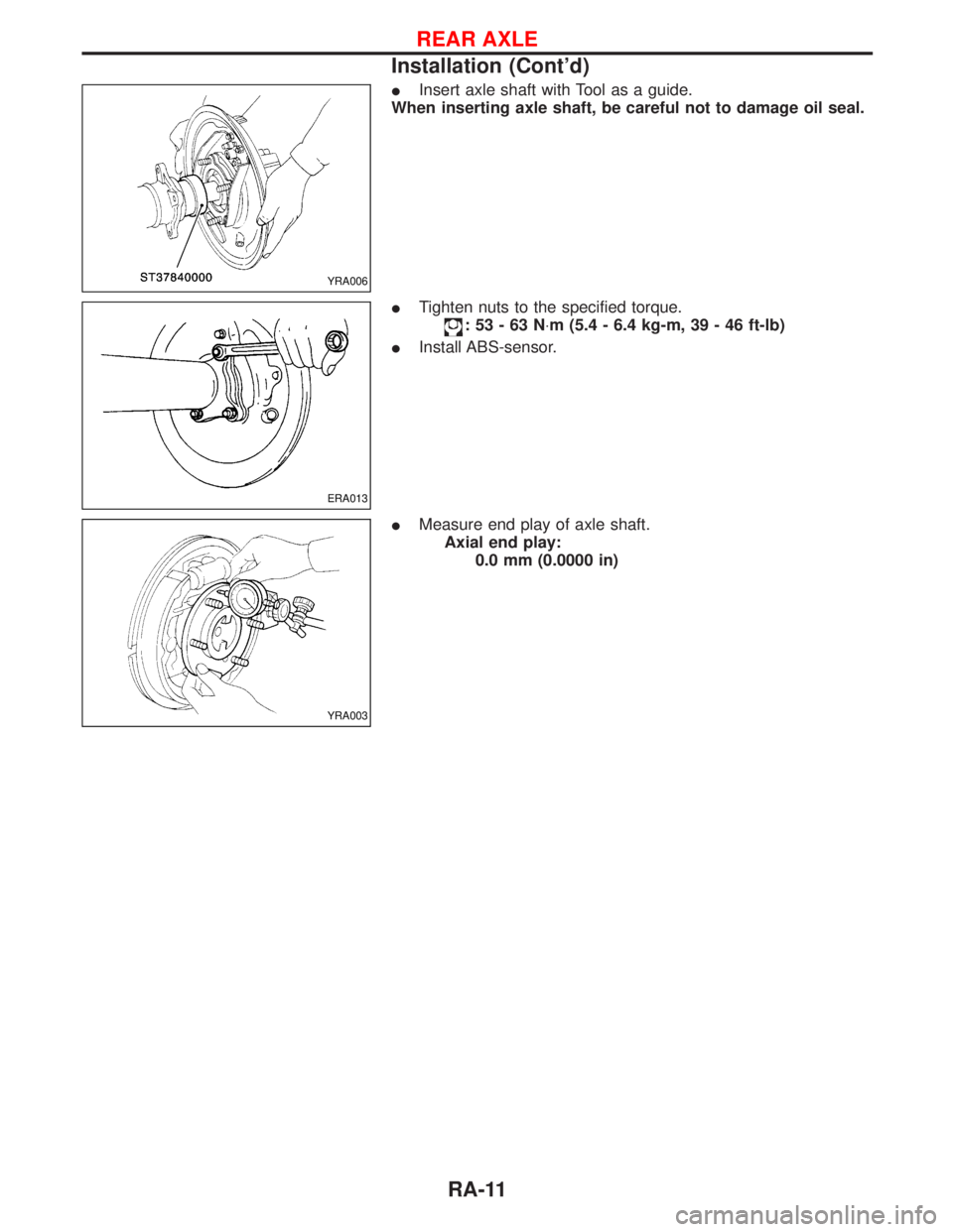
IInsert axle shaft with Tool as a guide.
When inserting axle shaft, be careful not to damage oil seal.
ITighten nuts to the specified torque.
:53-63N×m (5.4 - 6.4 kg-m, 39 - 46 ft-lb)
IInstall ABS-sensor.
IMeasure end play of axle shaft.
Axial end play:
0.0 mm (0.0000 in)
YRA006
ERA013
YRA003
REAR AXLE
Installation (Cont'd)
RA-11
Page 1617 of 1767
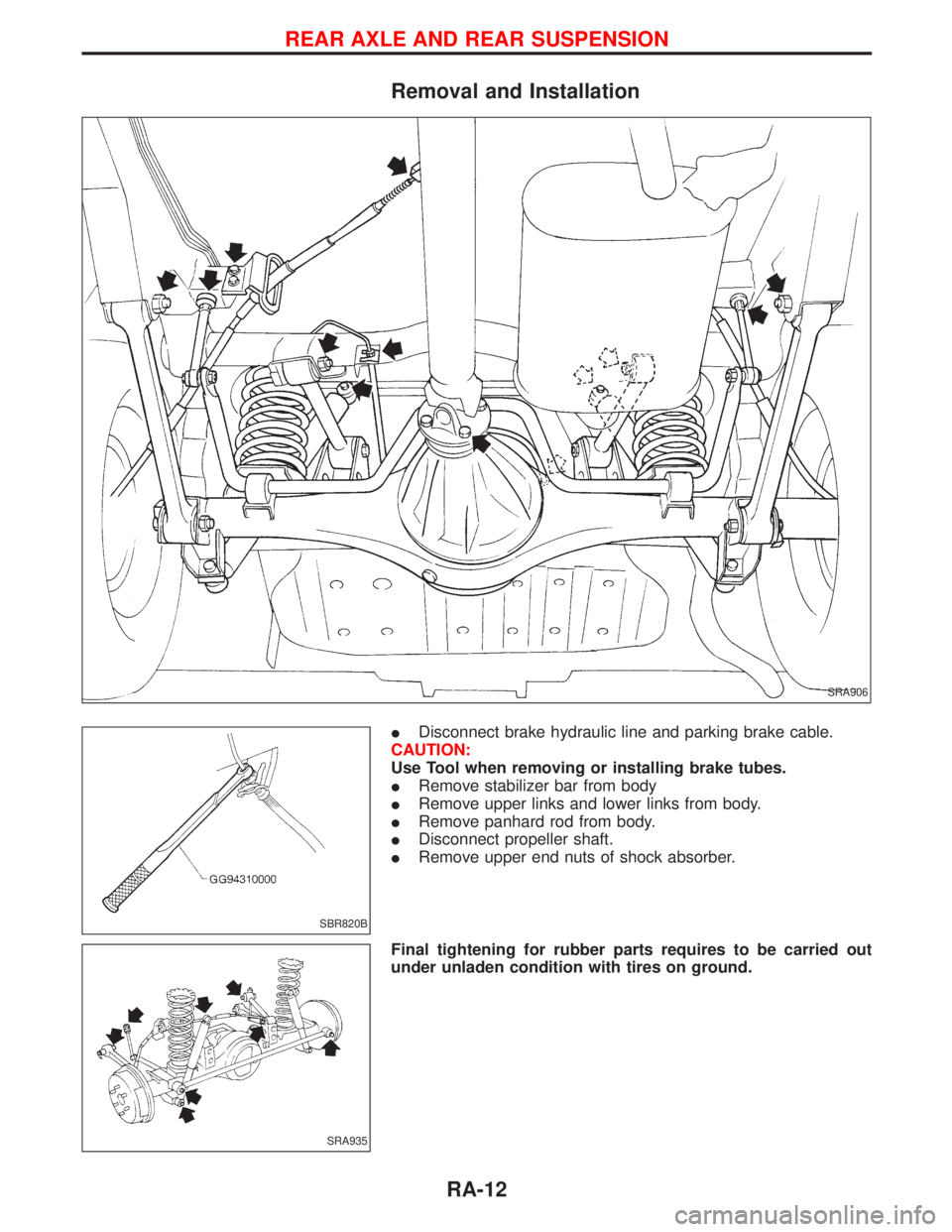
Removal and Installation
IDisconnect brake hydraulic line and parking brake cable.
CAUTION:
Use Tool when removing or installing brake tubes.
IRemove stabilizer bar from body
IRemove upper links and lower links from body.
IRemove panhard rod from body.
IDisconnect propeller shaft.
IRemove upper end nuts of shock absorber.
Final tightening for rubber parts requires to be carried out
under unladen condition with tires on ground.
SRA906
SBR820B
SRA935
REAR AXLE AND REAR SUSPENSION
RA-12
Page 1618 of 1767
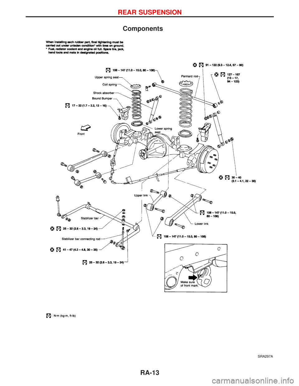
Components
SRA297A
REAR SUSPENSION
RA-13
Page 1619 of 1767
Coil Spring Shock Absorber
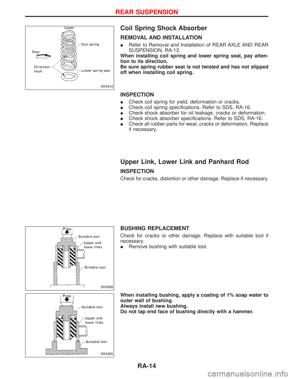
REMOVAL AND INSTALLATION
IRefer to Removal and Installation of REAR AXLE AND REAR
SUSPENSION, RA-12.
When installing coil spring and lower spring seat, pay atten-
tion to its direction.
Be sure spring rubber seat is not twisted and has not slipped
off when installing coil spring.
INSPECTION
ICheck coil spring for yield, deformation or cracks.
ICheck coil spring specifications. Refer to SDS, RA-16.
ICheck shock absorber for oil leakage, cracks or deformation.
ICheck shock absorber specifications. Refer to SDS, RA-16.
ICheck all rubber parts for wear, cracks or deformation. Replace
if necessary.
Upper Link, Lower Link and Panhard Rod
INSPECTION
Check for cracks, distortion or other damage. Replace if necessary.
BUSHING REPLACEMENT
Check for cracks or other damage. Replace with suitable tool if
necessary.
IRemove bushing with suitable tool.
When installing bushing, apply a coating of 1% soap water to
outer wall of bushing.
Always install new bushing.
Do not tap end face of bushing directly with a hammer.
SRA910
SRA898
SRA900
REAR SUSPENSION
RA-14
Page 1620 of 1767
INSTALLATION
When installing each link, pay attention to direction of bolts
and nuts. Refer to REAR SUSPENSION - Components, RA-13.
When installing each rubber part, final tightening must be car-
ried out under unladen condition with tires on ground.
Stabilizer Bar
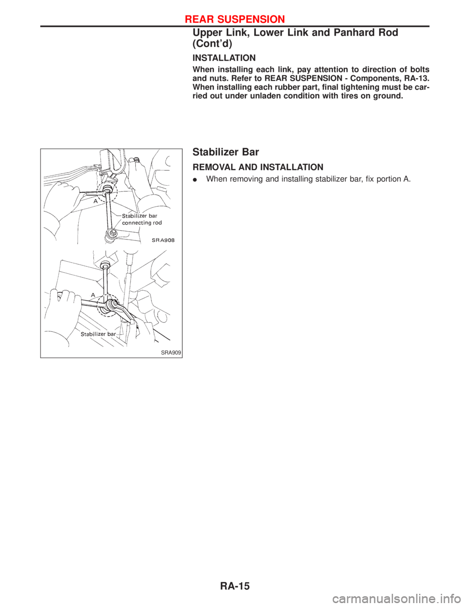
REMOVAL AND INSTALLATION
IWhen removing and installing stabilizer bar, fix portion A.
SRA909
REAR SUSPENSION
Upper Link, Lower Link and Panhard Rod
(Cont'd)
RA-15
Trending: wiper relay, four wheel drive, wheel bolt torque, headlamp, engine oil, trunk release, drain bolt
