NISSAN TERRANO 2002 Service Repair Manual
Manufacturer: NISSAN, Model Year: 2002, Model line: TERRANO, Model: NISSAN TERRANO 2002Pages: 1767, PDF Size: 41.51 MB
Page 1571 of 1767
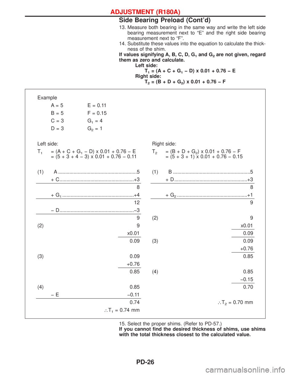
13. Measure both bearing in the same way and write the left side
bearing measurement next to ªEº and the right side bearing
measurement next to ªFº.
14. Substitute these values into the equation to calculate the thick-
ness of the shim.
If values signifying A, B, C, D, G
1and G2are not given, regard
them as zero and calculate.
Left side:
T
1=(A+C+G1þD)x0.01+0.76þE
Right side:
T
2=(B+D+G2)x0.01+0.76þF
Example
A = 5 E = 0.11
B = 5 F = 0.15
C=3 G
1=4
D=3 G
2=1
Left side: Right side:
T
1=(A+C+G1þD)x0.01+0.76þE
=(5+3+4þ3)x0.01 + 0.76 þ 0.11T2=(B+D+G2)x0.01+0.76þF
=(5+3+1)x0.01 + 0.76 þ 0.15
(1) A ........................................................5 (1) B .......................................................5
+ C.....................................................+3 + D ....................................................+3
88
+G
1...................................................+4 + G2..................................................+1
12 9
þ D.....................................................þ3
9 (2) 9
(2) 9 x0.01
x0.01 0.09
0.09 (3) 0.09
+0.76
(3) 0.09 0.85
+0.76
0.85 (4) 0.85
þ0.15
(4) 0.85 0.70
þ E þ0.11
0.74\T
2= 0.70 mm
\T
1= 0.74 mm
15. Select the proper shims. (Refer to PD-57.)
If you cannot find the desired thickness of shims, use shims
with the total thickness closest to the calculated value.
ADJUSTMENT (R180A)
Side Bearing Preload (Cont'd)
PD-26
Page 1572 of 1767
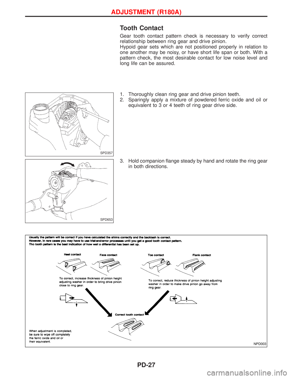
Tooth Contact
Gear tooth contact pattern check is necessary to verify correct
relationship between ring gear and drive pinion.
Hypoid gear sets which are not positioned properly in relation to
one another may be noisy, or have short life span or both. With a
pattern check, the most desirable contact for low noise level and
long life can be assured.
1. Thoroughly clean ring gear and drive pinion teeth.
2. Sparingly apply a mixture of powdered ferric oxide and oil or
equivalent to 3 or 4 teeth of ring gear drive side.
3. Hold companion flange steady by hand and rotate the ring gear
in both directions.
SPD357
SPD653
NPD003
ADJUSTMENT (R180A)
PD-27
Page 1573 of 1767
Extension Tube and Differential Side Shaft
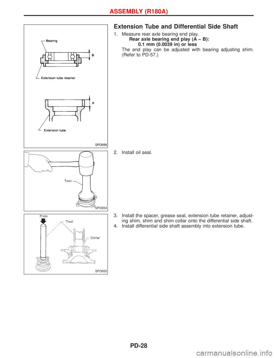
1. Measure rear axle bearing end play.
Rear axle bearing end play (A þ B):
0.1 mm (0.0039 in) or less
The end play can be adjusted with bearing adjusting shim.
(Refer to PD-57.)
2. Install oil seal.
3. Install the spacer, grease seal, extension tube retainer, adjust-
ing shim, shim and shim collar onto the differential side shaft.
4. Install differential side shaft assembly into extension tube.
SPD699
SPD654
SPD655
ASSEMBLY (R180A)
PD-28
Page 1574 of 1767
Differential Case
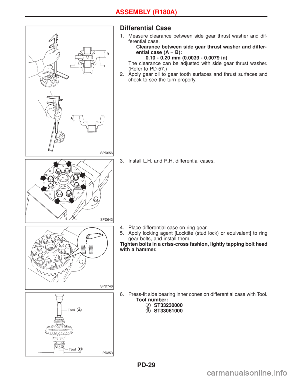
1. Measure clearance between side gear thrust washer and dif-
ferential case.
Clearance between side gear thrust washer and differ-
ential case (A þ B):
0.10 - 0.20 mm (0.0039 - 0.0079 in)
The clearance can be adjusted with side gear thrust washer.
(Refer to PD-57.)
2. Apply gear oil to gear tooth surfaces and thrust surfaces and
check to see the turn properly.
3. Install L.H. and R.H. differential cases.
4. Place differential case on ring gear.
5. Apply locking agent [Locktite (stud lock) or equivalent] to ring
gear bolts, and install them.
Tighten bolts in a criss-cross fashion, lightly tapping bolt head
with a hammer.
6. Press-fit side bearing inner cones on differential case with Tool.
Tool number:
q
AST33230000
q
BST33061000
SPD656
SPD643
SPD746
PD353
ASSEMBLY (R180A)
PD-29
Page 1575 of 1767
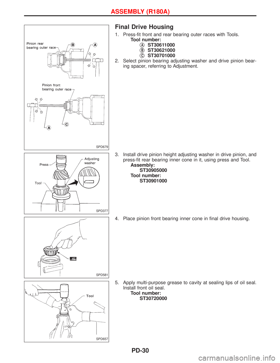
Final Drive Housing
1. Press-fit front and rear bearing outer races with Tools.
Tool number:
q
AST30611000
q
BST30621000
q
CST30701000
2. Select pinion bearing adjusting washer and drive pinion bear-
ing spacer, referring to Adjustment.
3. Install drive pinion height adjusting washer in drive pinion, and
press-fit rear bearing inner cone in it, using press and Tool.
Assembly:
ST30905000
Tool number:
ST30901000
4. Place pinion front bearing inner cone in final drive housing.
5. Apply multi-purpose grease to cavity at sealing lips of oil seal.
Install front oil seal.
Tool number:
ST30720000
SPD679
SPD377
SPD581
SPD657
ASSEMBLY (R180A)
PD-30
Page 1576 of 1767
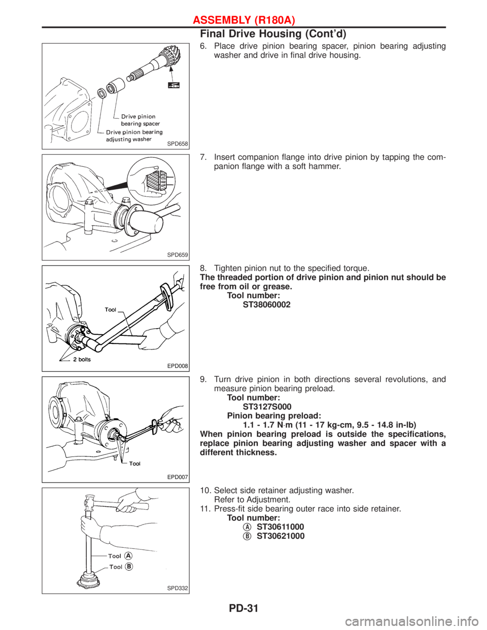
6. Place drive pinion bearing spacer, pinion bearing adjusting
washer and drive in final drive housing.
7. Insert companion flange into drive pinion by tapping the com-
panion flange with a soft hammer.
8. Tighten pinion nut to the specified torque.
The threaded portion of drive pinion and pinion nut should be
free from oil or grease.
Tool number:
ST38060002
9. Turn drive pinion in both directions several revolutions, and
measure pinion bearing preload.
Tool number:
ST3127S000
Pinion bearing preload:
1.1 - 1.7 N×m (11 - 17 kg-cm, 9.5 - 14.8 in-lb)
When pinion bearing preload is outside the specifications,
replace pinion bearing adjusting washer and spacer with a
different thickness.
10. Select side retainer adjusting washer.
Refer to Adjustment.
11. Press-fit side bearing outer race into side retainer.
Tool number:
q
AST30611000
q
BST30621000
SPD658
SPD659
EPD008
EPD007
SPD332
ASSEMBLY (R180A)
Final Drive Housing (Cont'd)
PD-31
Page 1577 of 1767
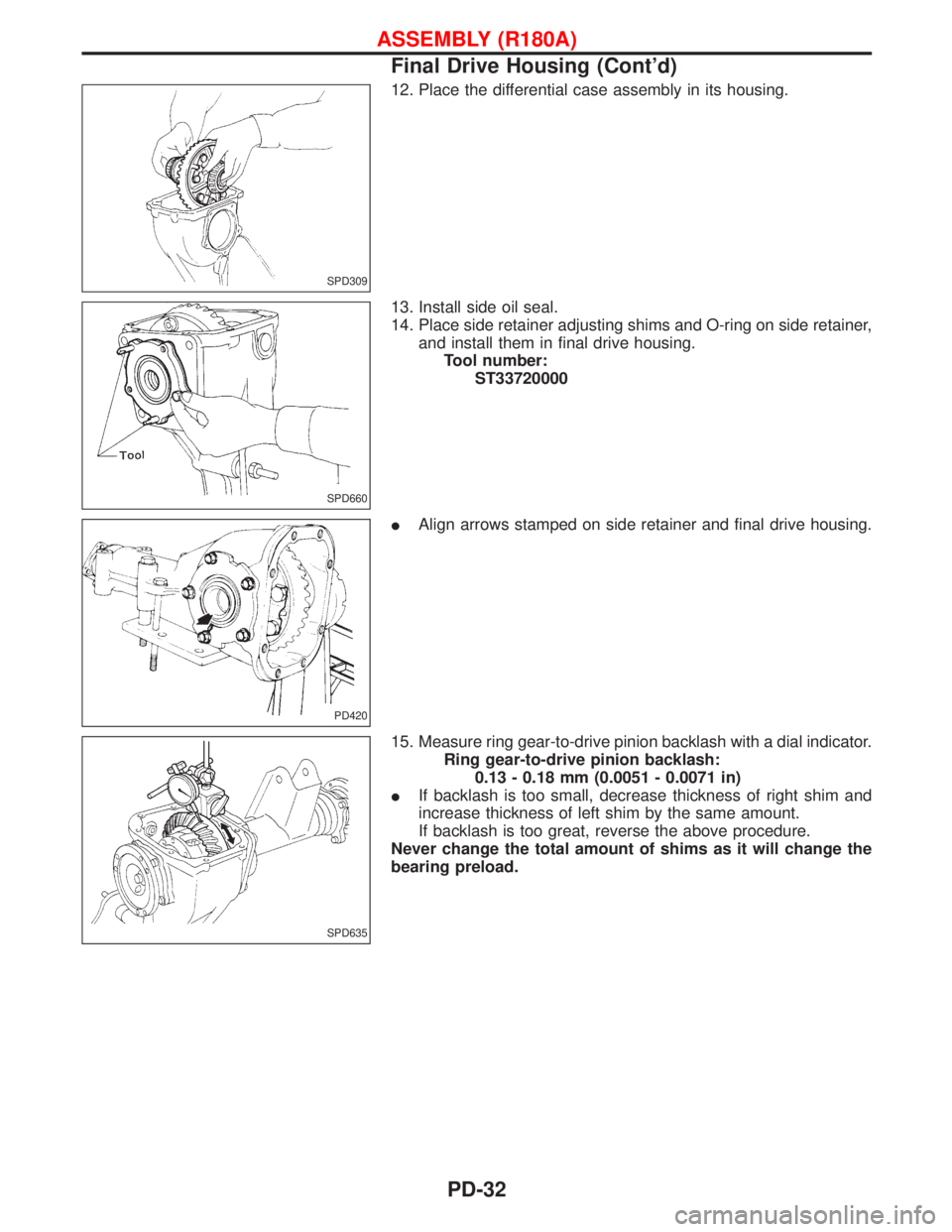
12. Place the differential case assembly in its housing.
13. Install side oil seal.
14. Place side retainer adjusting shims and O-ring on side retainer,
and install them in final drive housing.
Tool number:
ST33720000
IAlign arrows stamped on side retainer and final drive housing.
15. Measure ring gear-to-drive pinion backlash with a dial indicator.
Ring gear-to-drive pinion backlash:
0.13 - 0.18 mm (0.0051 - 0.0071 in)
IIf backlash is too small, decrease thickness of right shim and
increase thickness of left shim by the same amount.
If backlash is too great, reverse the above procedure.
Never change the total amount of shims as it will change the
bearing preload.
SPD309
SPD660
PD420
SPD635
ASSEMBLY (R180A)
Final Drive Housing (Cont'd)
PD-32
Page 1578 of 1767
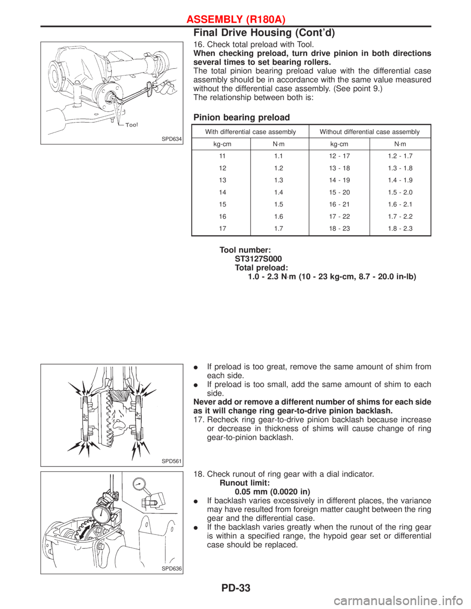
16. Check total preload with Tool.
When checking preload, turn drive pinion in both directions
several times to set bearing rollers.
The total pinion bearing preload value with the differential case
assembly should be in accordance with the same value measured
without the differential case assembly. (See point 9.)
The relationship between both is:
Pinion bearing preload
With differential case assembly Without differential case assembly
kg-cm N×m kg-cm N×m
11 1.1 12 - 17 1.2 - 1.7
12 1.2 13 - 18 1.3 - 1.8
13 1.3 14 - 19 1.4 - 1.9
14 1.4 15 - 20 1.5 - 2.0
15 1.5 16 - 21 1.6 - 2.1
16 1.6 17 - 22 1.7 - 2.2
17 1.7 18 - 23 1.8 - 2.3
Tool number:
ST3127S000
Total preload:
1.0 - 2.3 N×m (10 - 23 kg-cm, 8.7 - 20.0 in-lb)
IIf preload is too great, remove the same amount of shim from
each side.
IIf preload is too small, add the same amount of shim to each
side.
Never add or remove a different number of shims for each side
as it will change ring gear-to-drive pinion backlash.
17. Recheck ring gear-to-drive pinion backlash because increase
or decrease in thickness of shims will cause change of ring
gear-to-pinion backlash.
18. Check runout of ring gear with a dial indicator.
Runout limit:
0.05 mm (0.0020 in)
IIf backlash varies excessively in different places, the variance
may have resulted from foreign matter caught between the ring
gear and the differential case.
IIf the backlash varies greatly when the runout of the ring gear
is within a specified range, the hypoid gear set or differential
case should be replaced.
SPD634
SPD561
SPD636
ASSEMBLY (R180A)
Final Drive Housing (Cont'd)
PD-33
Page 1579 of 1767
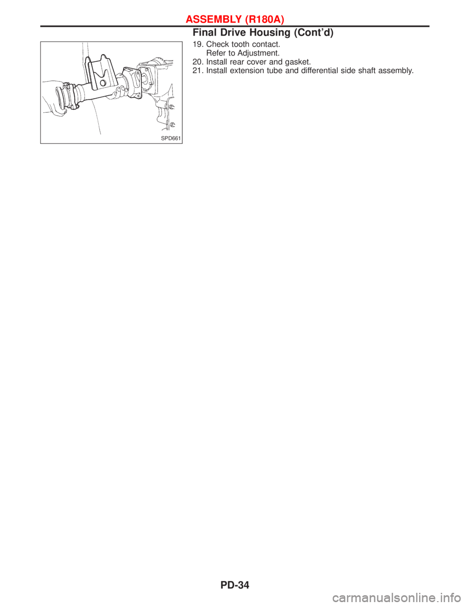
19. Check tooth contact.
Refer to Adjustment.
20. Install rear cover and gasket.
21. Install extension tube and differential side shaft assembly.
SPD661
ASSEMBLY (R180A)
Final Drive Housing (Cont'd)
PD-34
Page 1580 of 1767
EPD004
REAR FINAL DRIVE (H233B)
PD-35