NISSAN TERRANO 2004 Service Repair Manual
TERRANO 2004
NISSAN
NISSAN
https://www.carmanualsonline.info/img/5/57394/w960_57394-0.png
NISSAN TERRANO 2004 Service Repair Manual
Trending: keyless, air bleeding, wheel, manual transmission, set clock, immobilizer, inflation pressure
Page 1711 of 1833

Trouble Diagnosis
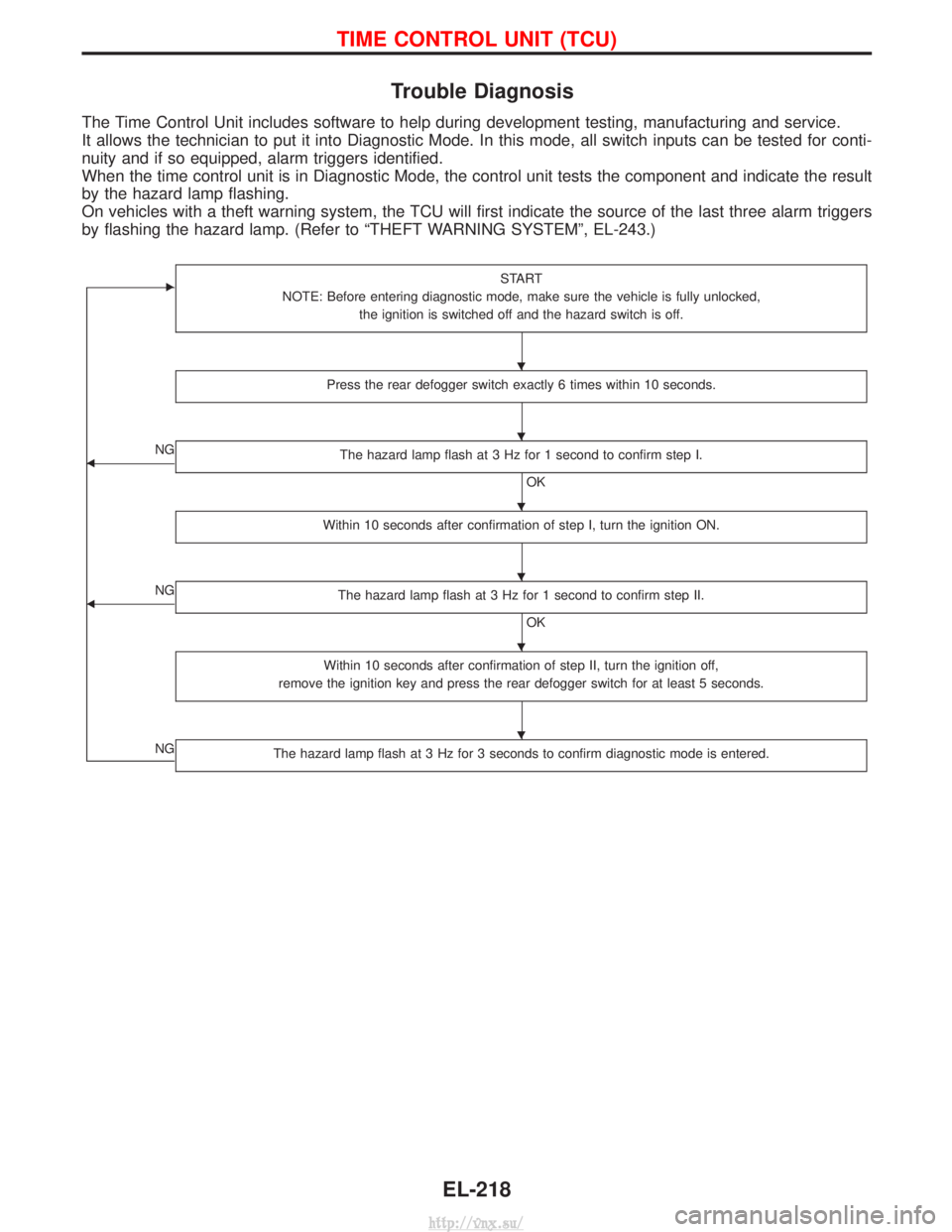
The Time Control Unit includes software to help during development testing, manufacturing and service.
It allows the technician to put it into Diagnostic Mode. In this mode, all switch inputs can be tested for conti-
nuity and if so equipped, alarm triggers identified.
When the time control unit is in Diagnostic Mode, the control unit tests the component and indicate the result
by the hazard lamp flashing.
On vehicles with a theft warning system, the TCU will first indicate the source of the last three alarm triggers
by flashing the hazard lamp. (Refer to ªTHEFT WARNING SYSTEMº, EL-243.)
ESTART
NOTE: Before entering diagnostic mode, make sure the vehicle is fully unlocked, the ignition is switched off and the hazard switch is off.
Press the rear defogger switch exactly 6 times within 10 seconds.
FNG The hazard lamp flash at 3 Hz for 1 second to confirm step I.
OK
Within 10 seconds after confirmation of step I, turn the ignition ON.
FNG The hazard lamp flash at 3 Hz for 1 second to confirm step II.
OK
Within 10 seconds after confirmation of step II, turn the ignition off,
remove the ignition key and press the rear defogger switch for at least 5 seconds.
NGThe hazard lamp flash at 3 Hz for 3 seconds to confirm diagnostic mode is entered.
H
H
H
H
H
H
TIME CONTROL UNIT (TCU)
EL-218
http://vnx.su/
Page 1712 of 1833

Checks
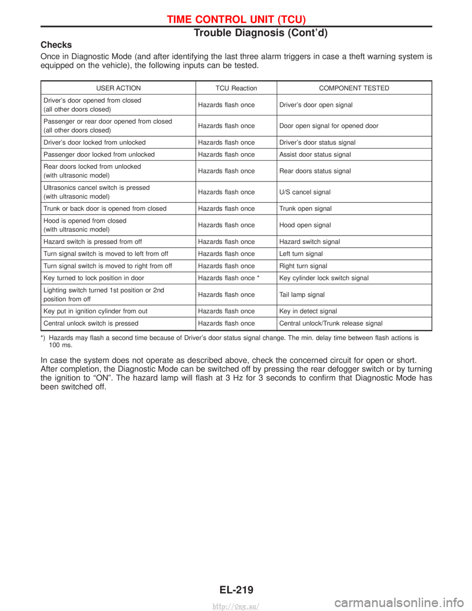
Once in Diagnostic Mode (and after identifying the last three alarm triggers in case a theft warning system is
equipped on the vehicle), the following inputs can be tested.
USER ACTIONTCU ReactionCOMPONENT TESTED
Driver's door opened from closed
(all other doors closed) Hazards flash once Driver's door open signal
Passenger or rear door opened from closed
(all other doors closed) Hazards flash once Door open signal for opened door
Driver's door locked from unlocked Hazards flash once Driver's door status signal
Passenger door locked from unlocked Hazards flash once Assist door status signal
Rear doors locked from unlocked
(with ultrasonic model) Hazards flash once Rear doors status signal
Ultrasonics cancel switch is pressed
(with ultrasonic model) Hazards flash once U/S cancel signal
Trunk or back door is opened from closed Hazards flash once Trunk open signal
Hood is opened from closed
(with ultrasonic model) Hazards flash once Hood open signal
Hazard switch is pressed from off Hazards flash once Hazard switch signal
Turn signal switch is moved to left from off Hazards flash once Left turn signal
Turn signal switch is moved to right from off Hazards flash once Right turn signal
Key turned to lock position in door Hazards flash once * Key cylinder lock switch signal
Lighting switch turned 1st position or 2nd
position from off Hazards flash once Tail lamp signal
Key put in ignition cylinder from out Hazards flash once Key in detect signal
Central unlock switch is pressed Hazards flash once Central unlock/Trunk release signal
*) Hazards may flash a second time because of Driver's door status signal change. The min. delay time between flash actions is 100 ms.
In case the system does not operate as described above, check the concerned circuit for open or short.
After completion, the Diagnostic Mode can be switched off by pressing the rear defogger switch or by turning
the ignition to ªONº. The hazard lamp will flash at 3 Hz for 3 seconds to confirm that Diagnostic Mode has
been switched off.
TIME CONTROL UNIT (TCU)
Trouble Diagnosis (Cont'd)
EL-219
http://vnx.su/
Page 1713 of 1833
Schematic
YEL752E
TIME CONTROL UNIT (TCU)
EL-220
http://vnx.su/
Page 1714 of 1833
YEL866E
TIME CONTROL UNIT (TCU)
Schematic (Cont'd)EL-221
http://vnx.su/
Page 1715 of 1833

System Description
NATS has the following immobilizer functions:
IThis version of NATS has dongle control unit to improve its anti-theft performance (RHD models). Dongle
control unit has its own ID which is registered into NATS IMMU. So if dongle unit is replaced, initialization
must be carried out.
I When malfunction of dongle unit is detected:
The security indicator lamp illuminates for about 15 minutes after ignition switch is turned to ON.
Ð When dongle control unit has a malfunction, and the indicator lamp is illuminated, engine can not be
started. However engine can be started only one time when security indicator lamp turns off in about
15 minutes after ignition switch is turned to ON.
I Since only NATS ignition keys, whose ID nos. have been registered into the ECM and IMMU of NATS,
allow the engine to run, operation of a stolen vehicle without a NATS registered key is prevented by NATS.
That is to say, NATS will immobilize the engine if someone tries to start it without the registered key of
NATS.
I All of the originally supplied ignition key IDs have been NATS registered.
If requested by the vehicle owner, a maximum of five key IDs can be registered into the NATS compo-
nents.
I The NATS security indicator (NATS security ind.) blinks when the ignition switch is in ªOFFº or ªACCº
position. Therefore, NATS warns outsiders that the vehicle is equipped with the anti-theft system.
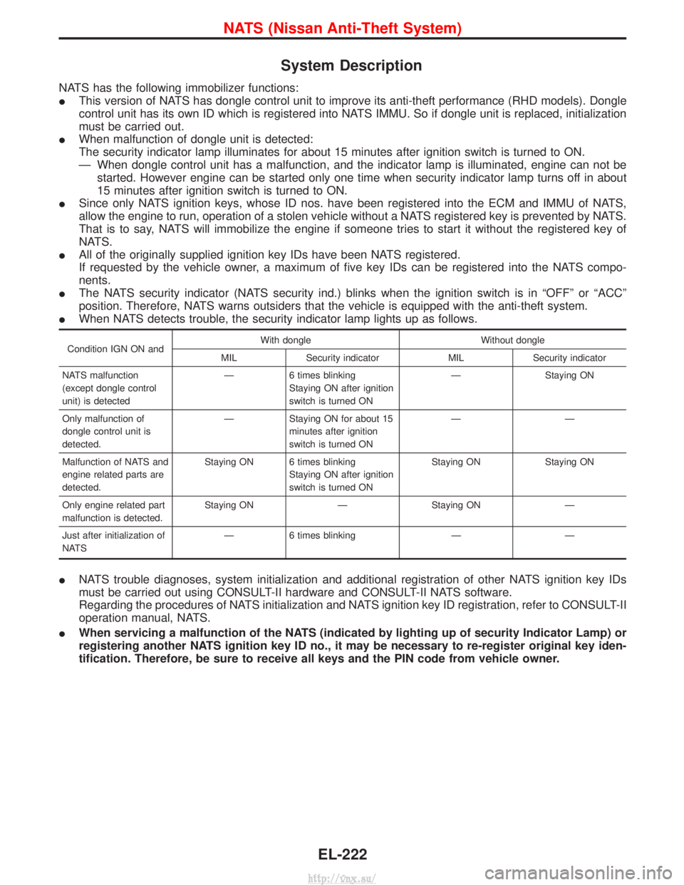
I When NATS detects trouble, the security indicator lamp lights up as follows.
Condition IGN ON and With dongle Without dongle
MIL Security indicator MIL Security indicator
NATS malfunction
(except dongle control
unit) is detected Ð
6 times blinking
Staying ON after ignition
switch is turned ON Ð
Staying ON
Only malfunction of
dongle control unit is
detected. Ð Staying ON for about 15
minutes after ignition
switch is turned ON ÐÐ
Malfunction of NATS and
engine related parts are
detected. Staying ON 6 times blinking
Staying ON after ignition
switch is turned ON Staying ON Staying ON
Only engine related part
malfunction is detected. Staying ON Ð Staying ON Ð
Just after initialization of
NATS Ð 6 times blinking Ð Ð
I
NATS trouble diagnoses, system initialization and additional registration of other NATS ignition key IDs
must be carried out using CONSULT-II hardware and CONSULT-II NATS software.
Regarding the procedures of NATS initialization and NATS ignition key ID registration, refer to CONSULT-II
operation manual, NATS.
I When servicing a malfunction of the NATS (indicated by lighting up of security Indicator Lamp) or
registering another NATS ignition key ID no., it may be necessary to re-register original key iden-
tification. Therefore, be sure to receive all keys and the PIN code from vehicle owner.
NATS (Nissan Anti-Theft System)
EL-222
http://vnx.su/
Page 1716 of 1833
System Composition
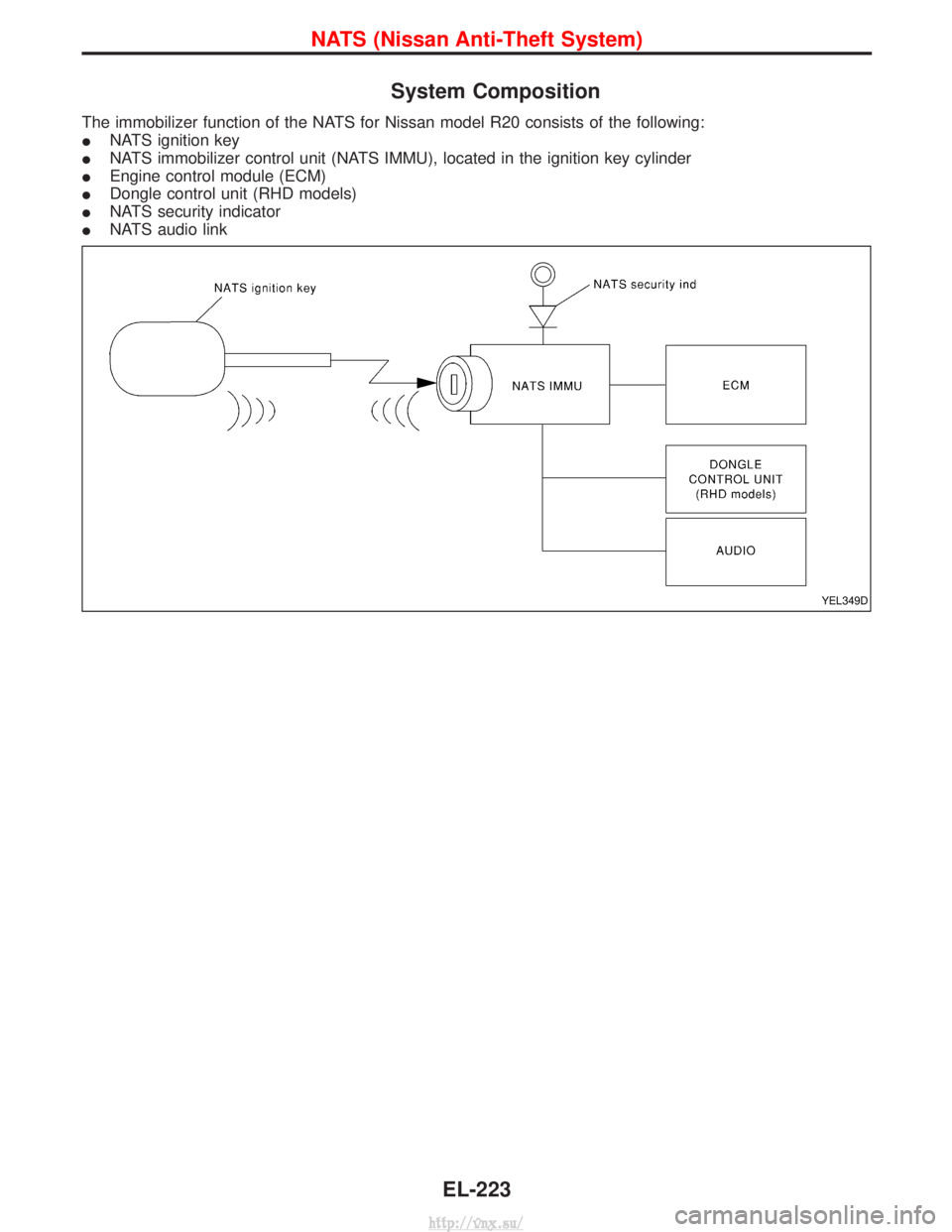
The immobilizer function of the NATS for Nissan model R20 consists of the following:
INATS ignition key
I NATS immobilizer control unit (NATS IMMU), located in the ignition key cylinder
I Engine control module (ECM)
I Dongle control unit (RHD models)
I NATS security indicator
I NATS audio link
YEL349D
NATS (Nissan Anti-Theft System)
EL-223
http://vnx.su/
Page 1717 of 1833
Component Parts Location
YEL320D
NATS (Nissan Anti-Theft System)
EL-224
http://vnx.su/
Page 1718 of 1833
Wiring Diagram Ð NATS Ð
LHD MODELS
YEL187D
NATS (Nissan Anti-Theft System)
EL-225
http://vnx.su/
Page 1719 of 1833
LHD MODELS
YEL753E
NATS (Nissan Anti-Theft System)
Wiring Diagram Ð NATS Ð (Cont'd)EL-226
http://vnx.su/
Page 1720 of 1833
RHD MODELS
YEL189D
NATS (Nissan Anti-Theft System)
Wiring Diagram Ð NATS Ð (Cont'd)EL-227
http://vnx.su/
Trending: drain bolt, low oil pressure, ECU, overheating, parking brake, timing belt, ABS


