alternator wiring NISSAN TERRANO 2004 Service Repair Manual
[x] Cancel search | Manufacturer: NISSAN, Model Year: 2004, Model line: TERRANO, Model: NISSAN TERRANO 2004Pages: 1833, PDF Size: 53.42 MB
Page 1464 of 1833

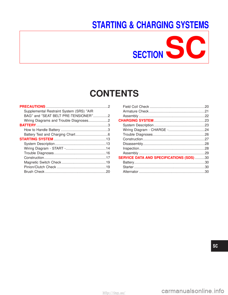
STARTING & CHARGING SYSTEMSSECTION
SC
CONTENTS
PRECAUTIONS ...............................................................2
Supplemental Restraint System (SRS) ²AIR
BAG² and²SEAT BELT PRE-TENSIONER² ...............2
Wiring Diagrams and Trouble Diagnoses....................2
BATTERY ........................................................................\
.3
How to Handle Battery ................................................3
Battery Test and Charging Chart .................................6
STARTING SYSTEM .....................................................13
System Description ....................................................13
Wiring Diagram - START -.........................................14
Trouble Diagnoses.....................................................16
Construction ...............................................................17
Magnetic Switch Check .............................................19
Pinion/Clutch Check ..................................................19
Brush Check ..............................................................20 Field Coil Check ........................................................20
Armature Check .........................................................21
Assembly ...................................................................22
CHARGING SYSTEM ....................................................23
System Description ....................................................23
Wiring Diagram - CHARGE -.....................................24
Trouble Diagnoses.....................................................26
Construction ...............................................................27
Disassembly...............................................................28
Inspection...................................................................28
Assembly ...................................................................29
SERVICE DATA AND SPECIFICATIONS (SDS) ..........30
Battery........................................................................\
30
Starter ........................................................................\
30
Alternator ...................................................................30
http://vnx.su/
Page 1640 of 1833

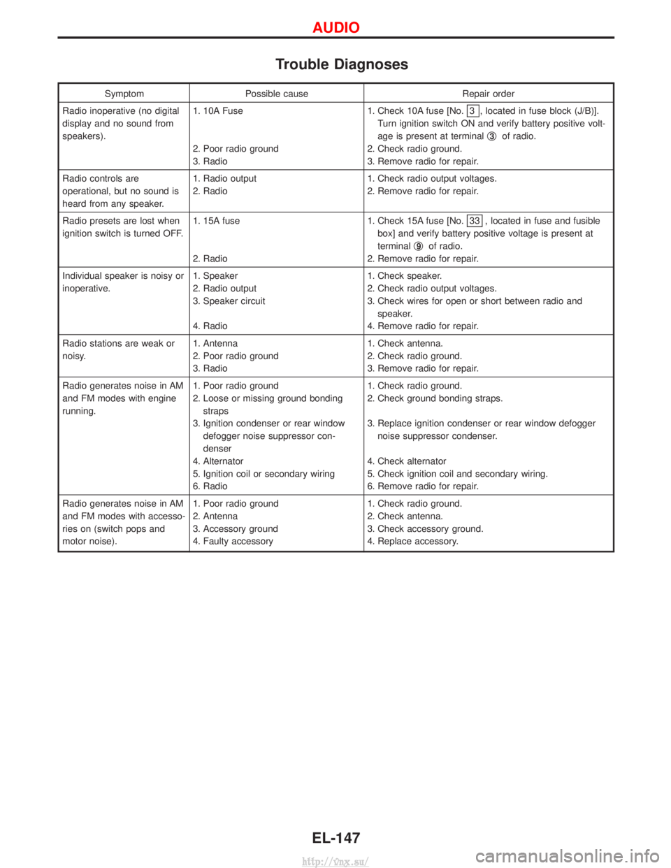
Trouble Diagnoses
SymptomPossible cause Repair order
Radio inoperative (no digital
display and no sound from
speakers). 1. 10A Fuse
2. Poor radio ground
3. Radio 1. Check 10A fuse [No.
3 , located in fuse block (J/B)].
Turn ignition switch ON and verify battery positive volt-
age is present at terminal q
3of radio.
2. Check radio ground.
3. Remove radio for repair.
Radio controls are
operational, but no sound is
heard from any speaker. 1. Radio output
2. Radio
1. Check radio output voltages.
2. Remove radio for repair.
Radio presets are lost when
ignition switch is turned OFF. 1. 15A fuse
2. Radio 1. Check 15A fuse [No.
33 , located in fuse and fusible
box] and verify battery positive voltage is present at
terminal q
9of radio.
2. Remove radio for repair.
Individual speaker is noisy or
inoperative. 1. Speaker
2. Radio output
3. Speaker circuit
4. Radio 1. Check speaker.
2. Check radio output voltages.
3. Check wires for open or short between radio and
speaker.
4. Remove radio for repair.
Radio stations are weak or
noisy. 1. Antenna
2. Poor radio ground
3. Radio 1. Check antenna.
2. Check radio ground.
3. Remove radio for repair.
Radio generates noise in AM
and FM modes with engine
running. 1. Poor radio ground
2. Loose or missing ground bonding
straps
3. Ignition condenser or rear window defogger noise suppressor con-
denser
4. Alternator
5. Ignition coil or secondary wiring
6. Radio 1. Check radio ground.
2. Check ground bonding straps.
3. Replace ignition condenser or rear window defogger
noise suppressor condenser.
4. Check alternator
5. Check ignition coil and secondary wiring.
6. Remove radio for repair.
Radio generates noise in AM
and FM modes with accesso-
ries on (switch pops and
motor noise). 1. Poor radio ground
2. Antenna
3. Accessory ground
4. Faulty accessory 1. Check radio ground.
2. Check antenna.
3. Check accessory ground.
4. Replace accessory.
AUDIO
EL-147
http://vnx.su/
Page 1827 of 1833

A
ABS (anti-lock brake system).........................BR-36
ABS - Wiring diagram ....................................BR-51
A/C air flow .......................................................HA-8
A/C compressor precaution..............................HA-5
A/C control operation (manual A/C) .................HA-6
A/C relay.........................................................HA-61
A/C symptom chart (manual A/C) ..................HA-36
A/C trouble diagnoses (manual A/C) .............HA-27
A/C, M - Wiring diagram ................................HA-43
ACC/SW - Wiring diagram ...........................EC-106
Accelerator control system ...........................FE-2, 5
Accelerator position sensor .........EC-130, 391, 394
Accelerator position switch ..................EC-392, 394
Accelerator switch (F/C) ...............................EC-104
Accelerator wire adjustment .............................FE-5
Accelerator work unit....................................EC-388
A/CCUT - Wiring diagram ............................EC-308
Air bag ..............................................................RS-8
Air bag disposal..............................................RS-22
Air bag precautions ...........................................GI-3
Air bleeding (hydraulic clutch) ..........................CL-6
Air bleeding for brake system ..........................BR-8
Air cleaner filter replacement ..............MA-5, 20, 24
Air conditioner cut control ..............EC-22, 334, 463
Air control cable adjustment...........................HA-62
Air flow meter - See Mass air flowsensor .................................................EC-88, 379
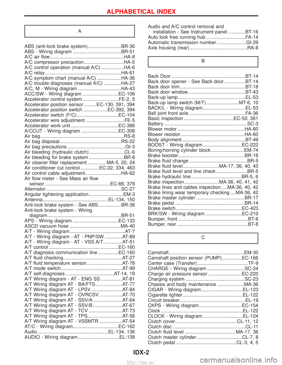
Alternator ........................................................SC-27
Angular tightening application..........................EM-3
Antenna.................................................EL-134, 150
Anti-lock brake system - See ABS .................BR-38
Anti-lock brake system - Wiring diagram .......................................................BR-51
APS - Wiring diagram ..................................EC-133
ASCD vacuum hose ......................................MA-40
A/T - Wiring diagram .........................................AT-7
A/T - Wiring diagram - AT - PNP/SW .............AT-89
A/T - Wiring diagram - AT - VSS A/T ..............AT-51
A/T control ....................................................EC-160
A/T diagnosis communication line ...............EC-160
A/T fluid checking ............................................AT-27
A/T fluid temperature sensor...........................AT-78
A/T mode switch..............................................AT-99
A/T self-diagnoses ....................................AT-14, 19
A/T Wiring diagram - AT - ENG SS ................AT-81
A/T Wiring diagram AT - BA/FTS ....................AT-77
A/T Wiring diagram AT - LPSV .......................AT-84
A/T Wiring diagram AT - OVRCSV .................AT-70
A/T Wiring diagram AT - SSV/A ......................AT-64
A/T Wiring diagram AT - SSV/B ......................AT-67
A/T Wiring diagram AT - TCV .........................AT-73
A/T Wiring diagram AT - TPS..........................AT-58
A/T Wiring diagram AT - VSSMTR .................AT-54
AT/C - Wiring diagram..................................EC-162
Audio .....................................................EL-134, 136
AUDIO - Wiring diagram ...............................EL-138 Audio and A/C control removal and
installation - See Instrument panel .............BT-16
Auto lock free running hub .............................FA-14
Automatic transmission number ......................GI-29
Axle housing (rear) ...........................................RA-8
B
Back Door .......................................................BT-14
Back door opener - See Back door ................BT-14
Back door trim.................................................BT-18
Back door window...........................................BT-43
Back-up lamp ..................................................EL-53
Back-up lamp switch (M/T) ........................MT-6, 10
BACK/L - Wiring diagram................................EL-53
Ball joint front axle ..........................................FA-36
Basic inspection .....................................EC-50, 361
Battery ..............................................................SC-3
Blower motor ..................................................HA-60
Blower resistor................................................HA-60
Body alignment ...............................................BT-49
BOOST - Wiring diagram .............................EC-222
Boring/horning cylinder block.........................EM-74
Brake booster .................................................BR-18
Brake fluid change ...........................................BR-5
Brake fluid level ...........................MA-17, 36, 40, 43
Brake fluid level and line check .......................BR-5
Brake hydraulic line......................................BR-5, 6
Brake inspection ..........................MA-36, 40, 41, 42
Brake lines and cables inspection.....MA-36, 40, 42
Brake lining wear temporary checking ....MA-36, 42
Brake master cylinder ....................................BR-17
Brake pedal ....................................................BR-14
Brake switch .................................................EC-423
BRK/SW - Wiring diagram ...........................EC-210
Bumper, front ....................................................BT-6
Bumper, rear .....................................................BT-8C
Camshaft ........................................................EM-30
Camshaft position sensor (PUMP)...............EC-166
Center case (Transfer) ......................................TF-9
CHARGE - Wiring diagram ............................SC-24
Charge air pressure sensor .........................EC-220
Charging system ............................................SC-23
Chassis and body maintenance ....................MA-36
CIGAR - Wiring diagram ...............................EL-123
Cigarette lighter.............................................EL-122
Circuit breaker.................................................EL-19
CKPS - Wiring diagram ................................EC-154
Clock .............................................................EL-122
CLOCK - Wiring diagram ..............................EL-124
Clutch cover ..............................................CL-11, 12
Clutch disc ......................................................CL-11
Clutch fluid level ......................................MA-17, 36
Clutch master cylinder ..................................CL-7, 8
Clutch pedal .............................................CL-3, 4, 5
ALPHABETICAL INDEX
IDX-2
http://vnx.su/
Page 1829 of 1833

F
Fan switch ......................................................HA-60
F/FOG - Wiring diagram .................................EL-55
Final drive disassembly............................PD-15, 37
Final drive pre-inspection .........................PD-15, 37
Final drive removal and installation ...............PD-15
Finisher, interior - See Trim ............................BT-18
Finisher, rear panel .........................................BT-18
Floor trim .........................................................BT-18
Fluid temperature sensor (A/T) .....................AT-146
Fluids .............................................MA-5, 17, 20, 36
Flywheel (clutch) .......................................CL-11, 12
Flywheel runout..............................................EM-94
Fog lamp, front .........................................EL-55, 57
Fog lamp, rear ................................................EL-58
Fork rod (M/T) ................................................MT-13
Forward clutch...............................................AT-162
Front axle ....................................................FA-4, 13
Front bumper ....................................................BT-6
Front case (Transfer) ..................................TF-9, 23
Front combination lamp removal andinstallation .....................................................BT-6
Front disc brake .............................................BR-27
Front door .......................................................BT-10
Front Door Trim...............................................BT-19
Front drive shaft (Transfer) .........................TF-9, 19
Front final drive disassembly (4WD) ..............PD-14
Front final drive removal and installa- tion (4WD) ............................................PD-12, 13
Front fog lamp ..........................................EL-55, 57
Front passenger air bag .................................RS-19
Front seat ........................................................BT-34
Front seat belt ..................................................RS-4
Front seat belt pre-tensioner ..........................RS-14
Front side air bag ...........................................RS-20
Front suspension ........................................FA-4, 29
Fuel cut control (at no load & high engine speed).....................................EC-22, 334
Fuel cut solenoid valve ................................EC-399
Fuel cut system ............................................EC-237
Fuel filler lid.......................................................BT-8
Fuel filter replacement...................MA-5, 20, 23, 33
Fuel gauge..................................FE-3, 6, EL-86, 98
Fuel injection system .............................EC-20, 329
Fuel injection timing feed back (Elec- tronic Fuel Injection Pump) ......................EC-197
Fuel precautions ................................................GI-6
Fuel pump and gauge ..............................FE-3, 6, 7
Fuel system ..................................................FE-3, 6
Fuel tank .......................................................FE-3, 6
Fuel temperature sensor ......................EC-123, 395
Fuse ................................................................EL-19
Fuse and fusible link box .............................Foldout
Fuse block ....................................................Foldout
Fusible link ......................................................EL-19 GGarage jack and safety stand .........................GI-31
Gauges .....................................................EL-82, 85
Gear components (M/T) ........MT-11, 14, 16, 21, 23
Generator - See Alternator .............................SC-27
GLOW - Wiring diagram...............................EC-246
Glow control system ....................EC-244, 334, 412
Glow plug .............................................EC-244, 413
Glow relay ............................................EC-246, 419
Grease .........................................MA-17, 39, 40, 44
Ground distribution..........................................EL-20
H
Harness connector ............................................EL-5
Harness connector inspection .........................GI-19
Harness layout ....EL-280, 281, 282, 298, 310, 312,320, 321, 322, 323, 324
Hazard warning lamp................................EL-61, 62
Headlamp ......EL-28, 32, 33, 34, 41, 42, 43, 46, 47
Headlamp aiming control .............EL-41, 42, 43, 46
Headlamp washer .........................................EL-118
Headlining - See Roof trim .............................BT-20
Heat up switch..............................................EC-265
Heated seat .......................................BT-36, EL-151
HEATER - Wiring diagram .............................HA-41
HEATUP - Wiring diagram ...........................EC-266
Height (Dimensions) ........................................GI-10
HFC134a (R134a) system precaution .............HA-3
HFC134a (R134a) system service procedure....................................................HA-15
HFC134a (R134a) system service tools ........HA-11
High clutch ....................................................AT-160
H/LAMP - Wiring diagram ............EL-28, 34, 43, 62
Hood..................................................................BT-6
Hood lock system .............................................BT-6
Horn ..............................................................EL-122
HORN - Wiring diagram................................EL-122
How to erase DTC for OBD system ......EC-33, 344
HSEAT - Wiring diagram...............................EL-151
I
Identification .....................................................HA-2
Identification plate .....................................GI-28, 29
Idle speed...............................................EC-50, 361
Idle speed inspection ...............................MA-20, 26
ILL - Wiring diagram .......................................EL-68
Illumination ................................................EL-67, 68
Injection nozzle ......................................EC-24, 336
Injection nozzle inspection ..................MA-5, 20, 25
Injection timing control valve ........................EC-403
INJPMP - Wiring diagram ...EC-126, 169, 176, 183, 190, 200, 240
Instrument panel .............................................BT-16
INT/L - Wiring diagram....................................EL-74
ALPHABETICAL INDEX
IDX-4
http://vnx.su/