heater NISSAN TIIDA 2007 Service Owners Manual
[x] Cancel search | Manufacturer: NISSAN, Model Year: 2007, Model line: TIIDA, Model: NISSAN TIIDA 2007Pages: 5883, PDF Size: 78.95 MB
Page 2387 of 5883

EC-1038
< SERVICE DATA AND SPECIFICATIONS (SDS) [MR18DE]
SERVICE DATA AND SPECIFICATIONS (SDS)
SERVICE DATA AND SPECIFICATIONS (SDS)
SERVICE DATA AND SPECIFICATIONS (SDS)
Idle SpeedINFOID:0000000001162007
*: Under the following conditions
A/C switch: OFF
Electric load: OFF (Lights, heater fan & rear window defogger)
Steering wheel: Kept in straight-ahead position
Ignition TimingINFOID:0000000001162008
*: Under the following conditions
A/C switch: OFF
Electric load: OFF (Lights, heater fan & rear window defogger)
Steering wheel: Kept in straight-ahead position
Calculated Load ValueINFOID:0000000001162009
Mass Air Flow SensorINFOID:0000000001162010
*: Engine is warmed up to normal operating temperature and running under no load.Condition Specification
No load* (in Neutral position) 700 ± 50 rpm
Condition Specification
No load* (in Neutral position) 15 ± 5° BTDC
Condition Specification (Using CONSULT-III or GST)
At idle10 – 35 %
At 2,500 rpm10 – 35 %
Supply voltageBattery voltage (11 – 14 V)
Output voltage at idle0.8 – 1.1V*
Mass air flow (Using CONSULT-III or GST)1.0 – 4.0 g·m/sec at idle*
2.0 – 10.0 g·m/sec at 2,500 rpm*
Page 2503 of 5883

EC-1154
< COMPONENT DIAGNOSIS >[K9K]
P0380 GLOW RELAY
P0380 GLOW RELAY
DTC LogicINFOID:0000000001162618
DTC DETECTION LOGIC
NOTE:
Conditions for applying the diagnostic procedure to the stored DTCs:
The DTC is declared present after attempts have been made to start the engine.
Special notes:
If the DTC is present, it will be difficult to start the vehicle, or even impossible when cold, or preheating will
be continuous and the heater plugs will deteriorate.
Diagnosis ProcedureINFOID:0000000001162619
1.CHECK GLOW RELAY POWER SUPPLY CIRCUIT
1. Turn ignition switch OFF.
2. Disconnect glow relay harness connector.
3. Turn ignition switch ON.
4. Check the voltage between glow relay connector and ground.
Is the inspection result normal?
YES >> GO TO 3.
NO >> GO TO 2.
2.DETECT MALFUNCTIONING PART
Check the following.
Harness connectors E8, F8
Harness for open or short between ECM and glow relay
Harness for open or short between IPDM E/R and glow relay
Harness for open and short between glow relay and battery
>> Repair open circuit or short to ground or short to power in harness or connectors.
3.CHECK GLOW RELAY INPUT CIRCUIT FOR OPEN AND SHORT-I
1. Turn ignition switch OFF.
2. Disconnect ECM harness connector.
3. Check the continuity between glow relay harness connector and ECM harness connector.
4. Also check harness for short to ground and short to power.
Is the inspection result normal?
YES >> GO TO 4.
NO >> Repair open circuit or short to ground or short to power in harness or connectors.
DTC No. Trouble diagnosis name Possible cause
P0380GLOW PLUG DIAGNOSTIC CONNECTION
CO: Open circuit
CC.0: Short circuit to ground
CC.1: Short circuit to +12V Harness or connectors
(The glow relay circuit is open or shorted.)
Glow relay
Glow relay
Ground Voltage
Connector Terminal
F55 3 Ground Battery voltage
Glow relay ECM
Continuity
Connector Terminal Connector Terminal
F55 9 F11 80 Existed
Page 2505 of 5883

EC-1156
< COMPONENT DIAGNOSIS >[K9K]
P0381 GLOW CONTROL SYSTEM
P0381 GLOW CONTROL SYSTEM
DTC LogicINFOID:0000000001162620
DTC DETECTION LOGIC
NOTE:
Conditions for applying the diagnostic procedure to the stored DTCs:
The DTC is declared present after several attempts have been made to start the engine.
Special notes:
If the DTC is present, it will be difficult to start the vehicle, or even impossible when cold, or preheating will
be continuous and the heater plugs will deteriorate.
Diagnosis ProcedureINFOID:0000000001162621
1.CHECK GLOW RELAY POWER SUPPLY CIRCUIT
1. Turn ignition switch OFF.
2. Disconnect glow relay harness connector.
3. Turn ignition switch ON.
4. Check the voltage between glow relay connector and ground.
Is the inspection result normal?
YES >> GO TO 3.
NO >> GO TO 2.
2.DETECT MALFUNCTIONING PART
Check the following.
Harness connectors E8, F8
Harness for open or short between ECM and glow relay
Harness for open or short between IPDM E/R glow relay
Harness for open and short between glow relay and battery
>> Repair open circuit or short to ground or short to power in harness or connectors.
3.CHECK GLOW RELAY INPUT CIRCUIT FOR OPEN AND SHORT-I
1. Turn ignition switch OFF.
2. Disconnect ECM harness connector.
3. Check the continuity between glow relay harness connector and ECM harness connector.
4. Also check harness for short to ground and short to power.
Is the inspection result normal?
YES >> GO TO 4.
NO >> Repair open circuit or short to ground or short to power in harness or connectors.
DTC No. Trouble diagnosis name Possible cause
P0381GLOW CONTROL UNIT CIRCUIT
CC.0: Short circuit to ground
CO.1: Open circuit or short circuit to +12V Harness or connectors
(The glow relay circuit is open or shorted.)
Glow relay
Glow plug
Glow relay
Ground Voltage
Connector Terminal
F55 3 Ground Battery voltage
Glow relay ECM
Continuity
Connector Terminal Connector Terminal
F55 9 F11 80 Existed
Page 2647 of 5883

EC-1298
< SERVICE DATA AND SPECIFICATIONS (SDS) [K9K]
SERVICE DATA AND SPECIFICATIONS (SDS)
SERVICE DATA AND SPECIFICATIONS (SDS)
SERVICE DATA AND SPECIFICATIONS (SDS)
Idle SpeedINFOID:0000000001162748
*: Under the following conditions
A/C switch: OFF
Electric load: OFF (Lights, glow plug, heater fan & rear window defogger)
Steering wheel: Kept in straight-ahead positionCondition Specification
No load* (in Neutral position) 800 ± 50 rpm
Page 2737 of 5883

EM-90
< REMOVAL AND INSTALLATION >[HR16DE]
ENGINE ASSEMBLY
If items or work required are not covered by the engine section, follow the procedures in the applica-
ble sections.
Always use the support point specified for lifting.
Use either 2-pole lift type or separate type lift as best you can. If board-on type is used for unavoid-
able reasons, support at the rear axle jacking point with a transmission jack or similar tool before
starting work, in preparation for the backward shift of center of gravity.
For supporting points for lifting and jacking point at rear axle, refer to GI-48, "
Garage Jack and
Safety Stand and 2-Pole Lift".
REMOVAL
Outline
Remove the engine and the transaxle assembly from the vehicle downward. Separate the engine and the tran-
saxle.
Preparation
1. Remove the hood assembly. Refer to DLK-214, "Removal and Installation".
2. Remove the cowl top cover and cowl top extension assembly. Refer to EXT-20, "
Removal and Installa-
tion".
3. Release fuel pressure. Refer to EC-377, "
Inspection" (EURO-OBD), EC-681, "Inspection" (WITHOUT
EURO-OBD).
4. Drain engine coolant from radiator. Refer to CO-11, "
Changing Engine Coolant".
CAUTION:
Perform this step when the engine is cold.
Never spill engine coolant on drive belt.
5. Drain the transmission fluid. Refer to TM-628, "
Draining" (M/T models), TM-171, "Changing A/T Fluid" (A/
T models).
6. Remove the following parts.
Engine undercover
Front road wheels and tires: Refer to WT-6, "
Rotation".
Front fender protector (RH and LH): Refer to EXT-22, "
Removal and Installation".
Battery and battery tray: Refer to PG-6, "
Removal and Installation".
Drive belt: Refer to EM-16, "
Removal and Installation".
Air duct and air cleaner case assembly: Refer to EM-27, "
Exploded View".
Radiator hose (upper and lower): Refer to CO-16, "
Component".
Disconnect cooling fan controller wiring harness.
Remove coolant reservoir tank.
Remove fan shroud and cooling fan assembly. Refer to CO-16, "
Component".
Engine Room LH
1. Disconnect all connections of engine harness around the engine mounting insulator (LH), and then tem-
porarily secure the engine harness into the engine side.
CAUTION:
Protect connectors using a resin bag against foreign materials.
2. Remove ground cable at transaxle side.
3. Disconnect fuel feed hose at engine side. Refer to EM-35, "
Exploded View".
4. Disconnect EVAP purge hose and brake booster vacuum hose.
5. Disconnect heater hoses, and install plugs them to prevent engine coolant from draining. Refer to CO-24,
"Exploded View".
6. Disconnect control linkage from transaxle. Refer to TM-189, "
Exploded View" (A/T), TM-630, "Exploded
View" (M/T).
7. Disconnect the clutch tube at transmission side. Refer to CL-12, "
Removal and Installation".
Engine Room RH
1. Remove ground cable between front cover and vehicle.
2. Remove generator and generator bracket; Refer to CHG-15, "
Removal and Installation".
3. Remove A/C compressor with piping connected from the engine. Temporarily secure it on the vehicle side
with a rope to avoid putting load on it. (with A/C models) Refer to HA-34, "
Removal and Installation of
Compressor - HR16DE".
Page 2855 of 5883

EM-208
< REMOVAL AND INSTALLATION >[MR18DE]
ENGINE ASSEMBLY
Always use the support point specified for lifting.
Use either 2-pole lift type or separate type lift as best you can. If board-on type is used for unavoid-
able reasons, support at the rear axle jacking point with a transmission jack or similar tool before
starting work, in preparation for the backward shift of center of gravity.
For supporting points for lifting and jacking point at rear axle, refer to GI-48, "
Garage Jack and
Safety Stand and 2-Pole Lift".
REMOVAL
Remove the engine and the transaxle assembly from the vehicle downward. Separate the engine and the tran-
saxle.
1. Remove engine undercover
2. Drain engine coolant from radiator. Refer to CO-35, "
Changing Engine Coolant".
CAUTION:
Perform this step when the engine is cold.
Do not spill engine coolant on drive belt.
3. Remove front fender protector (RH and LH); Refer to EXT-22, "
Removal and Installation".
4. Remove exhaust front tube; Refer to EX-10, "
Component".
5. Remove drive shafts (LH and RH) from steering knuckle. Refer to FA X - 7 , "
Removal and Installation".
6. Remove transaxle joint bolts which pierce at oil pan (upper) lower rear side. Refer to EM-207, "
Compo-
nent".
7. Remove rear torque rod (1).
8. Remove hood assembly. Refer to DLK-214, "
Removal and Installation".
9. Remove cowl top cover and cowl top extension assembly. Refer to EXT-20, "
Removal and Installation".
10. Release fuel pressure. Refer to EC-1035, "
Inspection".
11. Remove battery and battery tray; Refer to PG-6, "
Removal and Installation".
12. Remove drive belt; Refer to EM-142, "
Component".
13. Remove air duct and air cleaner case assembly; Refer to EM-154
.
14. Remove cooling fan assembly.
15. Remove radiator hose (upper and lower). Refer to CO-40, "
Component".
16. Disconnect all connections of engine harness around the engine mounting insulator (LH), and then tem-
porarily secure the engine harness into the engine side.
CAUTION:
Protect connectors using a resin bag to protect against foreign materials during the operation.
17. Disconnect fuel feed hose at engine side. Refer to EM-162, "
Component".
18. Disconnect heater hoses, and install plugs them to prevent engine coolant from draining. Refer to CO-47,
"Component".
19. Disconnect control cable from transaxle. Refer to TM-674, "
Exploded View".
20. Remove ground cable at transaxle side.
21. Remove ground cable between front cover and vehicle.
22. Remove generator. Refer to CHG-29, "
Removal and Installation".
23. Remove A/C compressor with piping connected from the engine. Temporarily secure it on the vehicle side
with a rope to avoid putting load on it. Refer to HA-32, "
Removal and Installation of Compressor -
MR18DE".
LBIA0460E
Page 2919 of 5883

EM-272
< ON-VEHICLE REPAIR >[K9K]
EGR SYSTEM
EGR SYSTEM
Exploded ViewINFOID:0000000001381474
Removal and InstallationINFOID:0000000001381475
REMOVAL
1. Remove battery ground cable.
2. Remove engine undercover using power tool.
3. Drain engine coolant. Refer to CO-58, "
Draining".
4. Remove lower radiator hose. Refer to CO-62, "
Exploded View".
5. Remove cowl top cover and cowl top extension assembly. Refer to EXT-20, "
Removal and Installation".
6. Remove air cleaner and air duct assembly. Refer to EM-269, "
Removal and Installation".
7. Remove charge air cooler inlet tubes at EGR assembly. Refer to EM-270, "
Exploded View".
8. Disconnect EGR volume control valve and electronic throttle control actuator connectors.
9. Disconnect heater hoses from EGR cooler cover.
10. Remove EGR cooler cover.
11. Remove front engine slinger.
12. Remove air inlet tube.
13. Remove RH fender protector. Refer to EXT-22, "
Removal and Installation".
1. Air inlet tube 2. Engine slinger 3. O-ring
4. Bracket 5. EGR tube 6. Gasket
7. EGR cooler 8. Gasket 9. EGR volume control valve
10. Gasket 11. EGR volume control valve housing 12. Clamp
13. EGR tube 14. Gasket 15. Gasket
16. Electronic throttle control actuator 17. O-ring 18. EGR cooler cover
A. To intake manifold B. To exhaust manifold
E1BIA0025GB
Page 2950 of 5883

ENGINE ASSEMBLY
EM-303
< REMOVAL AND INSTALLATION >[K9K]
C
D
E
F
G
H
I
J
K
L
MA
EM
N
P O
Remove engine and transaxle assembly from vehicle down ward. Separate engine and transaxle.
Preparation
Remove the following parts.
Battery ground cable.
Engine undercover.
LH and RH front wheels. Refer to WT-6, "
Rotation".
LH and RH fender protectors. Refer to EXT-22, "
Removal and Installation".
Engine Room
1. Drain engine coolant. Refer to CO-58, "Draining".
CAUTION:
Perform when engine is cold.
2. Remove lower radiator hose. Refer to CO-62, "
Exploded View".
3. Drain transaxle fluid. Refer to TM-672, "
Draining".
4. Disconnect clutch tube at clutch housing and drain clutch fluid.
NOTE:
Cover clutch tube ends to prevent contamination.
5. Remove hood. Refer to DLK-214, "
Removal and Installation".
6. Remove cowl top cover and cowl top extension assembly. Refer to EXT-20, "
Removal and Installation".
7. Remove battery and battery trap. Refer to PG-6, "
Removal and Installation".
8. Disconnect engine room harness from the engine side and position aside.
9. Remove the air duct (inlet). Refer to EM-269, "
Exploded View".
10. Remove engine cover.
11. Remove blow-by hose.
12. Remove air cleaner case and air duct (suction). Refer to EM-269, "
Removal and Installation".
13. Remove reservoir tank and hoses. Refer to CO-62, "
Exploded View".
14. Remove charge air cooler hoses and tubes. Refer to EM-270, "
Exploded View".
15. Remove vacuum hose. Refer to EM-280, "
Removal and Installation".
16. Disconnect fuel feed and return hoses, and plug it to prevent fuel from draining.
17. Remove radiator upper hose. Refer to CO-62, "
Exploded View".
18. Disconnect heater hoses.
19. Disconnect transaxle side harness.
20. Disconnect breather hose transaxle side.
21. Disconnect shift cable and select cable. Refer to TM-674, "
Exploded View".
22. Remove cooling fan. Refer to CO-64, "
Removal and Installation".
23. Remove radiator. Refer to CO-62, "
Exploded View".
24. Disconnect all the body-side vacuum hoses and air hoses at engine side.
Vehicle Underbody
1. Remove drive shaft assembly RH and LH. Refer to Removal and Installation.
2. Remove exhaust front tube. Refer to EX-14, "
Component".
3. Remove drive belt. Refer to EM-263, "
Removal and Installation".
4. Remove A/C compressor and position aside.
NOTE:
Secure it to body with a rope to avoid putting load on A/C lines.
5. Remove lower torque rod. Refer to EM-302, "
Exploded View".
Removal
Page 3222 of 5883
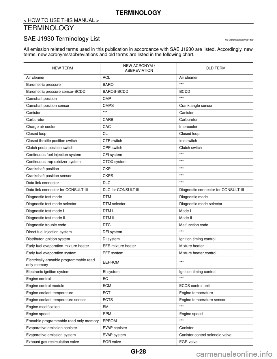
GI-28
< HOW TO USE THIS MANUAL >
TERMINOLOGY
TERMINOLOGY
SAE J1930 Terminology ListINFOID:0000000001691466
All emission related terms used in this publication in accordance with SAE J1930 are listed. Accordingly, new
terms, new acronyms/abbreviations and old terms are listed in the following chart.
NEW TERMNEW ACRONYM /
ABBREVIATIONOLD TERM
Air cleaner ACL Air cleaner
Barometric pressure BARO ***
Barometric pressure sensor-BCDD BAROS-BCDD BCDD
Camshaft position CMP ***
Camshaft position sensor CMPS Crank angle sensor
Canister *** Canister
Carburetor CARB Carburetor
Charge air cooler CAC Intercooler
Closed loop CL Closed loop
Closed throttle position switch CTP switch Idle switch
Clutch pedal position switch CPP switch Clutch switch
Continuous fuel injection system CFI system ***
Continuous trap oxidizer system CTOX system ***
Crankshaft position CKP ***
Crankshaft position sensor CKPS ***
Data link connector DLC ***
Data link connector for CONSULT-III DLC for CONSULT-III Diagnostic connector for CONSULT-III
Diagnostic test mode DTM Diagnostic mode
Diagnostic test mode selector DTM selector Diagnostic mode selector
Diagnostic test mode I DTM I Mode I
Diagnostic test mode II DTM II Mode II
Diagnostic trouble code DTC Malfunction code
Direct fuel injection system DFI system ***
Distributor ignition system DI system Ignition timing control
Early fuel evaporation-mixture heater EFE-mixture heater Mixture heater
Early fuel evaporation system EFE system Mixture heater control
Electrically erasable programmable read
only memoryEEPROM ***
Electronic ignition system EI system Ignition timing control
Engine control EC ***
Engine control module ECM ECCS control unit
Engine coolant temperature ECT Engine temperature
Engine coolant temperature sensor ECTS Engine temperature sensor
Engine modification EM ***
Engine speed RPM Engine speed
Erasable programmable read only memory EPROM ***
Evaporative emission canister EVAP canister Canister
Evaporative emission system EVAP system Canister control solenoid valve
Exhaust gas recirculation valve EGR valve EGR valve
Page 3283 of 5883
HA-1
VENTILATION, HEATER & AIR CONDITIONER
C
D
E
F
G
H
J
K
L
M
SECTION HA
A
B
HA
N
O
P
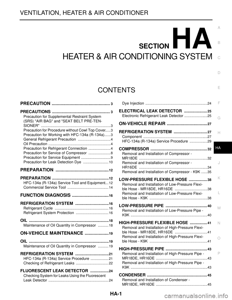
CONTENTS
HEATER & AIR CONDITIONING SYSTEM
PRECAUTION ...............................................3
PRECAUTIONS ...................................................3
Precaution for Supplemental Restraint System
(SRS) "AIR BAG" and "SEAT BELT PRE-TEN-
SIONER" ...................................................................
3
Precaution for Procedure without Cowl Top Cover ......3
Precaution for Working with HFC-134a (R-134a) ......3
General Refrigerant Precaution ................................4
Oil Precaution ............................................................4
Precaution for Refrigerant Connection ......................4
Precaution for Service of Compressor ......................8
Precaution for Service Equipment .............................9
Precaution for Leak Detection Dye .........................10
PREPARATION ...........................................12
PREPARATION ..................................................12
HFC-134a (R-134a) Service Tool and Equipment ....12
Commercial Service Tool ........................................14
FUNCTION DIAGNOSIS ..............................16
REFRIGERATION SYSTEM ..............................16
Refrigerant Cycle ....................................................16
Refrigerant System Protection ................................16
OIL ......................................................................18
Maintenance of Oil Quantity in Compressor ...........18
ON-VEHICLE MAINTENANCE ....................19
OIL ......................................................................19
Maintenance of Oil Quantity in Compressor ...........19
REFRIGERATION SYSTEM ..............................21
HFC-134a (R-134a) Service Procedure ..................21
Checking of Refrigerant Leaks ................................22
FLUORESCENT LEAK DETECTOR .................24
Checking System for Leaks Using the Fluorescent
Leak Detector ..........................................................
24
Dye Injection ............................................................24
ELECTRICAL LEAK DETECTOR ....................25
Electronic Refrigerant Leak Detector .......................25
ON-VEHICLE REPAIR .................................27
REFRIGERATION SYSTEM .............................27
Component ..............................................................27
HFC-134a (R-134a) Service Procedure ..................29
COMPRESSOR .................................................32
Removal and Installation of Compressor -
MR18DE ..................................................................
32
Removal and Installation of Compressor -
HR16DE ..................................................................
34
Removal and Installation of Compressor - K9K .......35
LOW-PRESSURE FLEXIBLE HOSE ................38
Removal and Installation of Low-Pressure Flexi-
ble Hose - MR18DE, HR16DE ................................
38
Removal and Installation of Low-Pressure Flexi-
ble Hose - K9K ........................................................
38
LOW-PRESSURE PIPE ....................................40
Removal and Installation of Low-Pressure Pipe -
K9K ..........................................................................
40
HIGH-PRESSURE FLEXIBLE HOSE ...............41
Removal and Installation of High-Pressure Flexi-
ble Hose - MR18DE, HR16DE ................................
41
Removal and Installation of High-Pressure Flexi-
ble Hose - K9K ........................................................
41
HIGH-PRESSURE PIPE ....................................43
Removal and Installation of High-Pressure Pipe -
MR18DE, HR16DE ..................................................
43
Removal and Installation of High-Pressure Pipe -
K9K ..........................................................................
43
CONDENSER ....................................................45
Removal and Installation of Condenser -
MR18DE, HR16DE ..................................................
45