heater NISSAN TIIDA 2007 Service Manual Online
[x] Cancel search | Manufacturer: NISSAN, Model Year: 2007, Model line: TIIDA, Model: NISSAN TIIDA 2007Pages: 5883, PDF Size: 78.95 MB
Page 2247 of 5883
EC-898
< COMPONENT DIAGNOSIS >[MR18DE]
P1143 HO2S1
YES >> GO TO 2.
NO >> Repair or replace ground connection.
2.RETIGHTEN HEATED OXYGEN SENSOR 1
Loosen and retighten heated oxygen sensor 1. Refer to EM-159, "
Removal and Installation".
>> GO TO 3.
3.CLEAR THE SELF-LEARNING DATA
1. Clear mixture ratio self-learning value, refer to EC-696, "
MIXTURE RATIO SELF-LEARNING VALUE
CLEAR : Special Repair Requirement".
2. Run engine for at least 10 minutes at idle speed.
Is the 1st trip DTC P0171 detected or difficult to start engine?
Yes >> Perform trouble diagnosis for DTC P0171. Refer to EC-844, "DTC Logic".
No >> GO TO 4.
4.CHECK HEATED OXYGEN SENSOR 1 HEATER
Refer to EC-829, "
Component Inspection".
Is inspection result normal?
YES >> GO TO 5.
NO >> Replace heated oxygen sensor 1.
5.CHECK INTERMITTENT INCIDENT
Perform GI-55, "
Intermittent Incident".
Is the inspection result normal?
YES >> GO TO 6.
NO >> Repair or replace.
6.REPLACE HEATED OXYGEN SENSOR 1
Replace heated oxygen sensor 1.
>> INSPECTION END
Component InspectionINFOID:0000000001161875
1.INSPECTION START
Do you have CONSULT-III?
Do you have CONSULT-III?
YES >> GO TO 2.
NO >> GO TO 3.
2.CHECK HEATED OXYGEN SENSOR 1
With CONSULT-III
1. Start engine and warm it up to normal operating temperature.
2. Set “POST TRIGGER” to 100% in “DATA MONITOR” mode with CONSULT-III.
3. Select “HO2S1 (B1)” and “HO2S1 MNTR (B1)”.
4. Hold engine speed at 2,000 rpm under no load during the following steps.
5. Touch “RECORD” on CONSULT-III screen.
Page 2250 of 5883
P1144 HO2S1
EC-901
< COMPONENT DIAGNOSIS >[MR18DE]
C
D
E
F
G
H
I
J
K
L
MA
EC
N
P O
P1144 HO2S1
DescriptionINFOID:0000000001161876
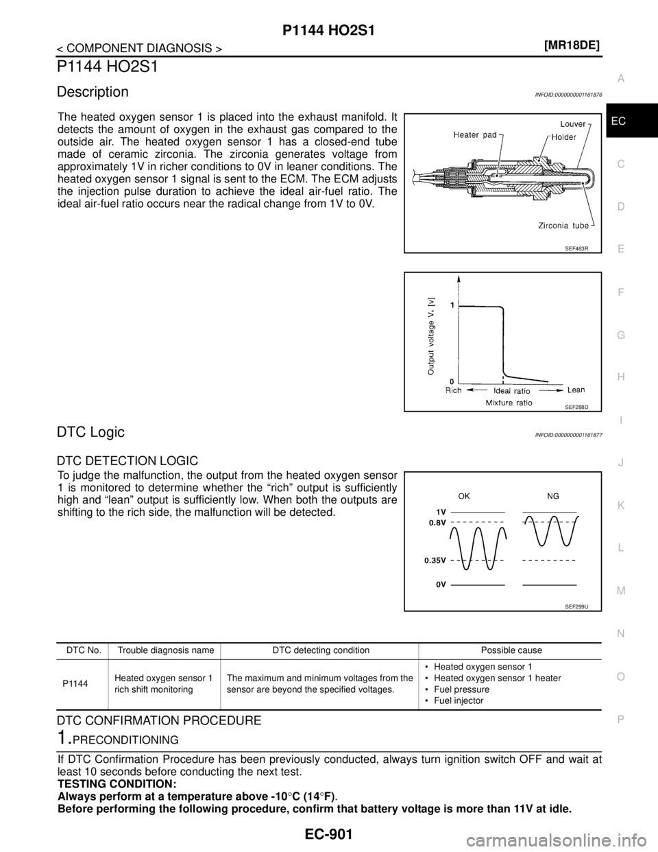
The heated oxygen sensor 1 is placed into the exhaust manifold. It
detects the amount of oxygen in the exhaust gas compared to the
outside air. The heated oxygen sensor 1 has a closed-end tube
made of ceramic zirconia. The zirconia generates voltage from
approximately 1V in richer conditions to 0V in leaner conditions. The
heated oxygen sensor 1 signal is sent to the ECM. The ECM adjusts
the injection pulse duration to achieve the ideal air-fuel ratio. The
ideal air-fuel ratio occurs near the radical change from 1V to 0V.
DTC LogicINFOID:0000000001161877
DTC DETECTION LOGIC
To judge the malfunction, the output from the heated oxygen sensor
1 is monitored to determine whether the “rich” output is sufficiently
high and “lean” output is sufficiently low. When both the outputs are
shifting to the rich side, the malfunction will be detected.
DTC CONFIRMATION PROCEDURE
1.PRECONDITIONING
If DTC Confirmation Procedure has been previously conducted, always turn ignition switch OFF and wait at
least 10 seconds before conducting the next test.
TESTING CONDITION:
Always perform at a temperature above -10°C (14°F).
Before performing the following procedure, confirm that battery voltage is more than 11V at idle.
SEF463R
SEF288D
SEF299U
DTC No. Trouble diagnosis name DTC detecting condition Possible cause
P1144Heated oxygen sensor 1
rich shift monitoringThe maximum and minimum voltages from the
sensor are beyond the specified voltages. Heated oxygen sensor 1
Heated oxygen sensor 1 heater
Fuel pressure
Fuel injector
Page 2252 of 5883
P1144 HO2S1
EC-903
< COMPONENT DIAGNOSIS >[MR18DE]
C
D
E
F
G
H
I
J
K
L
MA
EC
N
P O
2.RETIGHTEN HEATED OXYGEN SENSOR 1
Loosen and retighten heated oxygen sensor 1. Refer to EM-159, "
Removal and Installation".
>> GO TO 3.
3.CLEAR THE SELF-LEARNING DATA
1. Clear the mixture ratio self-learning value, refer to EC-696, "
MIXTURE RATIO SELF-LEARNING VALUE
CLEAR : Special Repair Requirement".
2. Run engine for at least 10 minutes at idle speed.
Is the 1st trip DTC P0172 detected or difficult to start engine?
Yes >> Perform trouble diagnosis for DTC P0172. Refer to EC-844, "DTC Logic".
No >> GO TO 4
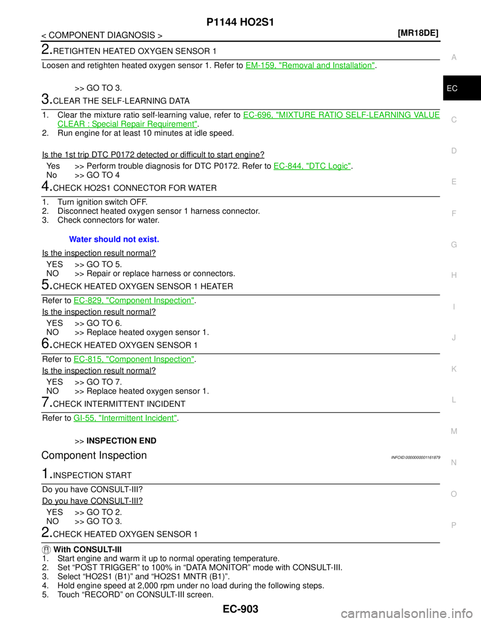
4.CHECK HO2S1 CONNECTOR FOR WATER
1. Turn ignition switch OFF.
2. Disconnect heated oxygen sensor 1 harness connector.
3. Check connectors for water.
Is the inspection result normal?
YES >> GO TO 5.
NO >> Repair or replace harness or connectors.
5.CHECK HEATED OXYGEN SENSOR 1 HEATER
Refer to EC-829, "
Component Inspection".
Is the inspection result normal?
YES >> GO TO 6.
NO >> Replace heated oxygen sensor 1.
6.CHECK HEATED OXYGEN SENSOR 1
Refer to EC-815, "
Component Inspection".
Is the inspection result normal?
YES >> GO TO 7.
NO >> Replace heated oxygen sensor 1.
7.CHECK INTERMITTENT INCIDENT
Refer to GI-55, "
Intermittent Incident".
>>INSPECTION END
Component InspectionINFOID:0000000001161879
1.INSPECTION START
Do you have CONSULT-III?
Do you have CONSULT-III?
YES >> GO TO 2.
NO >> GO TO 3.
2.CHECK HEATED OXYGEN SENSOR 1
With CONSULT-III
1. Start engine and warm it up to normal operating temperature.
2. Set “POST TRIGGER” to 100% in “DATA MONITOR” mode with CONSULT-III.
3. Select “HO2S1 (B1)” and “HO2S1 MNTR (B1)”.
4. Hold engine speed at 2,000 rpm under no load during the following steps.
5. Touch “RECORD” on CONSULT-III screen.Water should not exist.
Page 2322 of 5883
ELECTRICAL LOAD SIGNAL
EC-973
< COMPONENT DIAGNOSIS >[MR18DE]
C
D
E
F
G
H
I
J
K
L
MA
EC
N
P O
ELECTRICAL LOAD SIGNAL
DescriptionINFOID:0000000001161966
The electrical load signal (Headlamp switch signal, rear window defogger switch signal, etc.) is transferred
through the CAN communication line from BCM to ECM via IPDM E/R.
Component Function CheckINFOID:0000000001161967
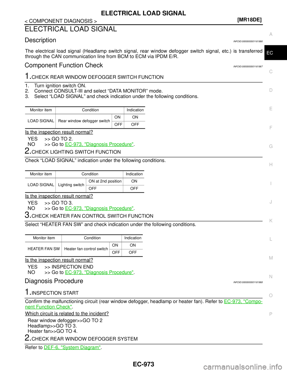
1.CHECK REAR WINDOW DEFOGGER SWITCH FUNCTION
1. Turn ignition switch ON.
2. Connect CONSULT-III and select “DATA MONITOR” mode.
3. Select “LOAD SIGNAL” and check indication under the following conditions.
Is the inspection result normal?
YES >> GO TO 2.
NO >> Go to EC-973, "
Diagnosis Procedure".
2.CHECK LIGHTING SWITCH FUNCTION
Check “LOAD SIGNAL” indication under the following conditions.
Is the inspection result normal?
YES >> GO TO 3.
NO >> Go to EC-973, "
Diagnosis Procedure".
3.CHECK HEATER FAN CONTROL SWITCH FUNCTION
Select “HEATER FAN SW” and check indication under the following conditions.
Is the inspection result normal?
YES >> INSPECTION END
NO >> Go to EC-973, "
Diagnosis Procedure".
Diagnosis ProcedureINFOID:0000000001161968
1.INSPECTION START
Confirm the malfunctioning circuit (rear window defogger, headlamp or heater fan). Refer to EC-973, "
Compo-
nent Function Check".
Which circuit is related to the incident?
Rear window defogger>>GO TO 2
Headlamp>>GO TO 3.
Heater fan>>GO TO 4.
2.CHECK REAR WINDOW DEFOGGER SYSTEM
Refer to DEF-6, "
System Diagram".
Monitor item Condition Indication
LOAD SIGNAL Rear window defogger switchON ON
OFF OFF
Monitor item Condition Indication
LOAD SIGNAL Lighting switchON at 2nd position ON
OFF OFF
Monitor item Condition Indication
HEATER FAN SW Heater fan control switchON ON
OFF OFF
Page 2323 of 5883
EC-974
< COMPONENT DIAGNOSIS >[MR18DE]
ELECTRICAL LOAD SIGNAL
>> INSPECTION END
3.CHECK HEADLAMP SYSTEM
Refer to EXL-10, "
System Diagram" (XENON TYPE) or EXL-8, "System Diagram" (HALOGEN TYPE).
>> INSPECTION END
4.CHECK HEATER FAN CONTROL SYSTEM
Refer to GI-55, "
Intermittent Incident".
>> INSPECTION END
Page 2340 of 5883
ECM
EC-991
< ECU DIAGNOSIS >[MR18DE]
C
D
E
F
G
H
I
J
K
L
MA
EC
N
P O
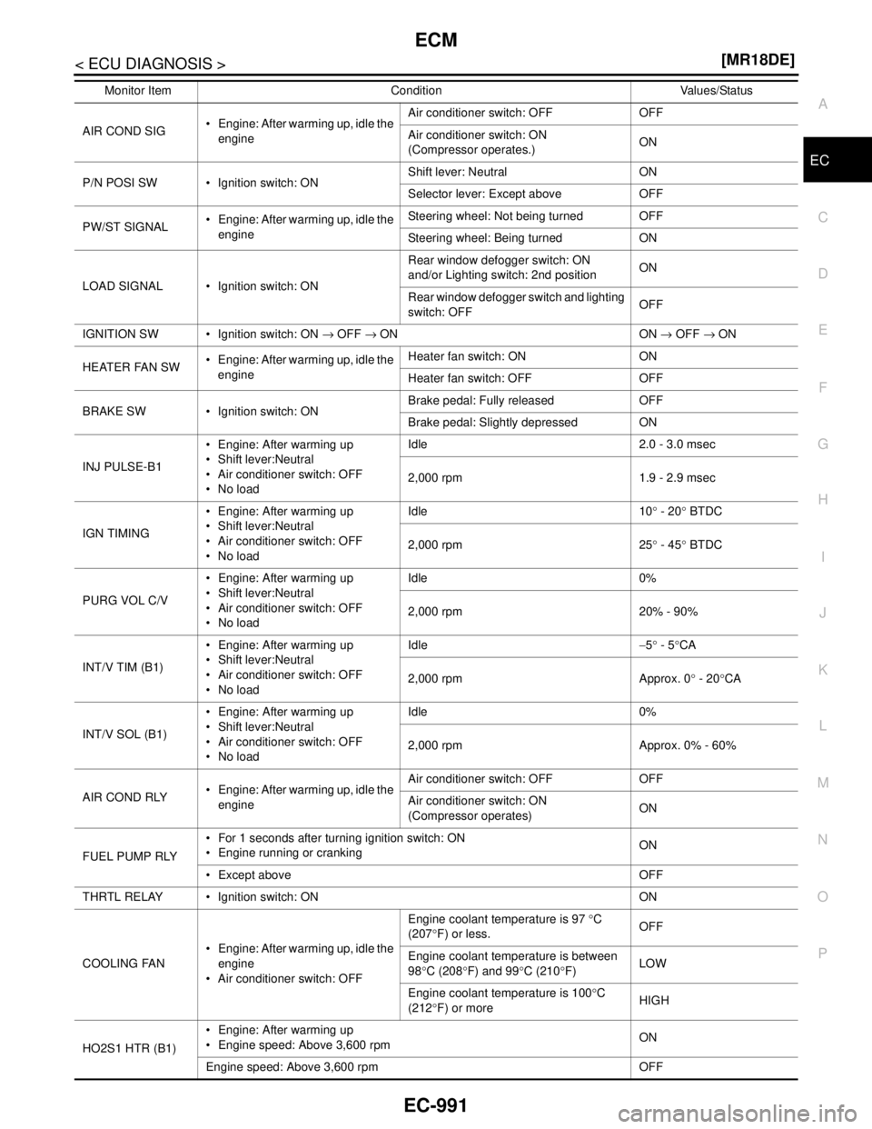
AIR COND SIG Engine: After warming up, idle the
engineAir conditioner switch: OFF OFF
Air conditioner switch: ON
(Compressor operates.)ON
P/N POSI SW Ignition switch: ONShift lever: Neutral ON
Selector lever: Except above OFF
PW/ST SIGNAL Engine: After warming up, idle the
engineSteering wheel: Not being turned OFF
Steering wheel: Being turned ON
LOAD SIGNAL Ignition switch: ONRear window defogger switch: ON
and/or Lighting switch: 2nd positionON
Rear window defogger switch and lighting
switch: OFFOFF
IGNITION SW Ignition switch: ON → OFF → ON ON → OFF → ON
HEATER FAN SW Engine: After warming up, idle the
engineHeater fan switch: ON ON
Heater fan switch: OFF OFF
BRAKE SW Ignition switch: ONBrake pedal: Fully released OFF
Brake pedal: Slightly depressed ON
INJ PULSE-B1 Engine: After warming up
Shift lever:Neutral
Air conditioner switch: OFF
No loadIdle 2.0 - 3.0 msec
2,000 rpm 1.9 - 2.9 msec
IGN TIMING Engine: After warming up
Shift lever:Neutral
Air conditioner switch: OFF
No loadIdle 10° - 20° BTDC
2,000 rpm 25° - 45° BTDC
PURG VOL C/V Engine: After warming up
Shift lever:Neutral
Air conditioner switch: OFF
No loadIdle 0%
2,000 rpm 20% - 90%
INT/V TIM (B1) Engine: After warming up
Shift lever:Neutral
Air conditioner switch: OFF
No loadIdle−5° - 5°CA
2,000 rpm Approx. 0° - 20°CA
INT/V SOL (B1) Engine: After warming up
Shift lever:Neutral
Air conditioner switch: OFF
No loadIdle 0%
2,000 rpm Approx. 0% - 60%
AIR COND RLY Engine: After warming up, idle the
engineAir conditioner switch: OFF OFF
Air conditioner switch: ON
(Compressor operates)ON
FUEL PUMP RLY For 1 seconds after turning ignition switch: ON
Engine running or crankingON
Except above OFF
THRTL RELAY Ignition switch: ON ON
COOLING FAN Engine: After warming up, idle the
engine
Air conditioner switch: OFFEngine coolant temperature is 97 °C
(207°F) or less.OFF
Engine coolant temperature is between
98°C (208°F) and 99°C (210°F)LOW
Engine coolant temperature is 100°C
(212°F) or moreHIGH
HO2S1 HTR (B1) Engine: After warming up
Engine speed: Above 3,600 rpmON
Engine speed: Above 3,600 rpm OFF Monitor Item Condition Values/Status
Page 2342 of 5883
ECM
EC-993
< ECU DIAGNOSIS >[MR18DE]
C
D
E
F
G
H
I
J
K
L
MA
EC
N
P O
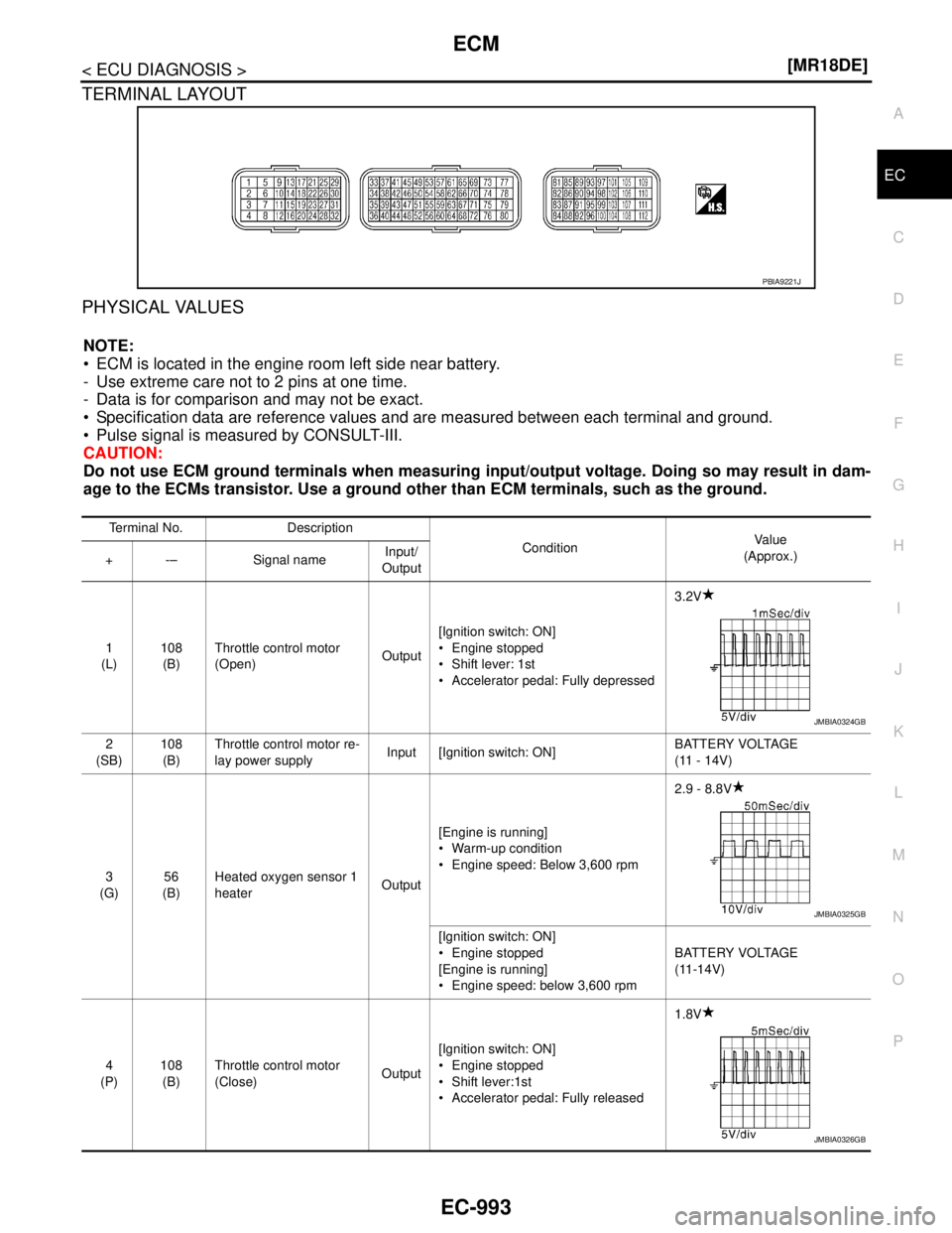
TERMINAL LAYOUT
PHYSICAL VALUES
NOTE:
ECM is located in the engine room left side near battery.
- Use extreme care not to 2 pins at one time.
- Data is for comparison and may not be exact.
Specification data are reference values and are measured between each terminal and ground.
Pulse signal is measured by CONSULT-III.
CAUTION:
Do not use ECM ground terminals when measuring input/output voltage. Doing so may result in dam-
age to the ECMs transistor. Use a ground other than ECM terminals, such as the ground.
PBIA9221J
Terminal No. Description
ConditionVa l u e
(Approx.)
+ -– Signal nameInput/
Output
1
(L)108
(B)Throttle control motor
(Open)Output[Ignition switch: ON]
Engine stopped
Shift lever: 1st
Accelerator pedal: Fully depressed3.2V
2
(SB)108
(B)Throttle control motor re-
lay power supplyInput [Ignition switch: ON]BATTERY VOLTAGE
(11 - 14V)
3
(G)56
(B)Heated oxygen sensor 1
heaterOutput[Engine is running]
Warm-up condition
Engine speed: Below 3,600 rpm2.9 - 8.8V
[Ignition switch: ON]
Engine stopped
[Engine is running]
Engine speed: below 3,600 rpmBATTERY VOLTAGE
(11-14V)
4
(P)108
(B)Throttle control motor
(Close)Output[Ignition switch: ON]
Engine stopped
Shift lever:1st
Accelerator pedal: Fully released1.8V
JMBIA0324GB
JMBIA0325GB
JMBIA0326GB
Page 2343 of 5883
EC-994
< ECU DIAGNOSIS >[MR18DE]
ECM
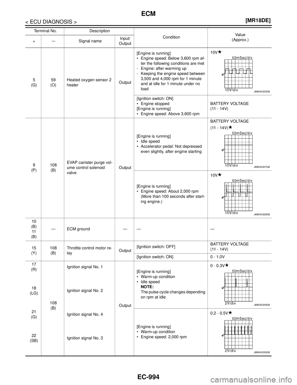
5
(G)59
(O)Heated oxygen sensor 2
heaterOutput[Engine is running]
Engine speed: Below 3,600 rpm af-
ter the following conditions are met
- Engine: after warming up
- Keeping the engine speed between
3,500 and 4,000 rpm for 1 minute
and at idle for 1 minute under no
load10V
[Ignition switch: ON]
Engine stopped
[Engine is running]
Engine speed: Above 3,600 rpmBATTERY VOLTAGE
(11 - 14V)
9
(P)108
(B)EVAP canister purge vol-
ume control solenoid
valveOutput[Engine is running]
Idle speed
Accelerator pedal: Not depressed
even slightly, after engine startingBATTERY VOLTAGE
(11 - 14V)
[Engine is running]
Engine speed: About 2,000 rpm
(More than 100 seconds after start-
ing engine.)10V
10
(B)
11
(B)— ECM ground — — —
15
(Y)108
(B)Throttle control motor re-
layOutput[Ignition switch: OFF]BATTERY VOLTAGE
(11 - 14V)
[Ignition switch: ON] 0 - 1.0V
17
(R)
108
(B)Ignition signal No. 1
Output[Engine is running]
Warm-up condition
Idle speed
NOTE:
The pulse cycle changes depending
on rpm at idle0 - 0.3V
18
(LG)Ignition signal No. 2
21
(G)Ignition signal No. 4
[Engine is running]
Warm-up condition
Engine speed: 2,000 rpm0.2 - 0.5V
22
(SB)Ignition signal No. 3 Terminal No. Description
ConditionVa l u e
(Approx.)
+-– Signal nameInput/
Output
JMBIA0325GB
JMBIA0327GB
JMBIA0328GB
JMBIA0329GB
JMBIA0330GB
Page 2368 of 5883
ECM
EC-1019
< ECU DIAGNOSIS >[MR18DE]
C
D
E
F
G
H
I
J
K
L
MA
EC
N
P O
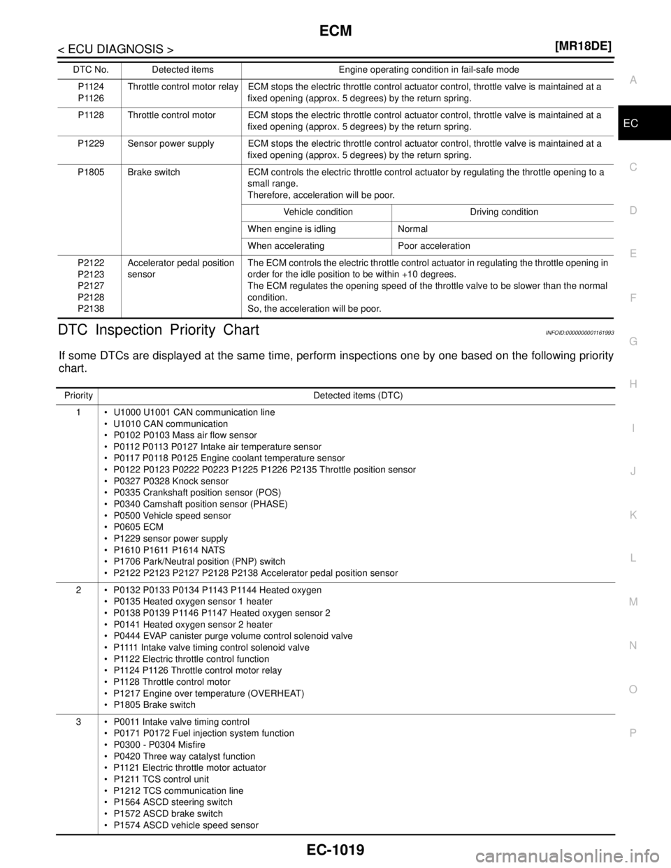
DTC Inspection Priority ChartINFOID:0000000001161993
If some DTCs are displayed at the same time, perform inspections one by one based on the following priority
chart.
P1124
P1126Throttle control motor relay ECM stops the electric throttle control actuator control, throttle valve is maintained at a
fixed opening (approx. 5 degrees) by the return spring.
P1128 Throttle control motor ECM stops the electric throttle control actuator control, throttle valve is maintained at a
fixed opening (approx. 5 degrees) by the return spring.
P1229 Sensor power supply ECM stops the electric throttle control actuator control, throttle valve is maintained at a
fixed opening (approx. 5 degrees) by the return spring.
P1805 Brake switch ECM controls the electric throttle control actuator by regulating the throttle opening to a
small range.
Therefore, acceleration will be poor.
Vehicle condition Driving condition
When engine is idling Normal
When accelerating Poor acceleration
P2122
P2123
P2127
P2128
P2138Accelerator pedal position
sensorThe ECM controls the electric throttle control actuator in regulating the throttle opening in
order for the idle position to be within +10 degrees.
The ECM regulates the opening speed of the throttle valve to be slower than the normal
condition.
So, the acceleration will be poor. DTC No. Detected items Engine operating condition in fail-safe mode
Priority Detected items (DTC)
1 U1000 U1001 CAN communication line
U1010 CAN communication
P0102 P0103 Mass air flow sensor
P0112 P0113 P0127 Intake air temperature sensor
P0117 P0118 P0125 Engine coolant temperature sensor
P0122 P0123 P0222 P0223 P1225 P1226 P2135 Throttle position sensor
P0327 P0328 Knock sensor
P0335 Crankshaft position sensor (POS)
P0340 Camshaft position sensor (PHASE)
P0500 Vehicle speed sensor
P0605 ECM
P1229 sensor power supply
P1610 P1611 P1614 NATS
P1706 Park/Neutral position (PNP) switch
P2122 P2123 P2127 P2128 P2138 Accelerator pedal position sensor
2 P0132 P0133 P0134 P1143 P1144 Heated oxygen
P0135 Heated oxygen sensor 1 heater
P0138 P0139 P1146 P1147 Heated oxygen sensor 2
P0141 Heated oxygen sensor 2 heater
P0444 EVAP canister purge volume control solenoid valve
P 1111 I n t a k e v a l v e t i m i n g c o n t r o l s o l e n o i d v a l v e
P1122 Electric throttle control function
P1124 P1126 Throttle control motor relay
P1128 Throttle control motor
P1217 Engine over temperature (OVERHEAT)
P1805 Brake switch
3 P0011 Intake valve timing control
P0171 P0172 Fuel injection system function
P0300 - P0304 Misfire
P0420 Three way catalyst function
P1121 Electric throttle motor actuator
P1211 TCS control unit
P1212 TCS communication line
P1564 ASCD steering switch
P1572 ASCD brake switch
P1574 ASCD vehicle speed sensor
Page 2372 of 5883
ECM
EC-1023
< ECU DIAGNOSIS >[MR18DE]
C
D
E
F
G
H
I
J
K
L
MA
EC
N
P O
Sea level
Flat road
Ambient air temperature: 20 - 30°C (68 - 86°F)
Diagnosis is performed as quickly as possible under normal conditions.
Under different conditions [For example: ambient air temperature other than 20 - 30°C (68 - 86°F)], diagno-
sis may also be performed.
Pattern 1:
The engine is started at the engine coolant temperature of −10 to 35°C (14 to 95°F)
(where the voltage between the ECM terminal 46 and ground is 3.0 - 4.3V).
The engine must be operated at idle speed until the engine coolant temperature is greater than 70°C
(158°F) (where the voltage between the ECM terminal 46 and ground is lower than 1.4V).
The engine is started at the fuel tank temperature of warmer than 0°C (32°F) (where the voltage
between the ECM terminal 95 and ground is less than 4.1V).
Pattern 2:
When steady-state driving is performed again even after it is interrupted, each diagnosis can be conducted.
In this case, the time required for diagnosis may be extended.
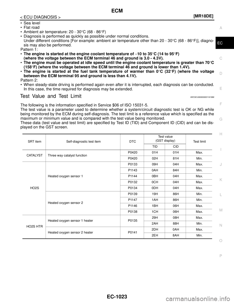
Test Value and Test LimitINFOID:0000000001161996
The following is the information specified in Service $06 of ISO 15031-5.
The test value is a parameter used to determine whether a system/circuit diagnostic test is OK or NG while
being monitored by the ECM during self-diagnosis. The test limit is a reference value which is specified as the
maximum or minimum value and is compared with the test value being monitored.
These data (test value and test limit) are specified by Test ID (TID) and Component ID (CID) and can be dis-
played on the GST screen.
SRT item Self-diagnostic test item DTCTe s t v a l u e
(GST display)
Te s t l i m i t
TID CID
CATALYST Three way catalyst functionP0420 01H 01H Max.
P0420 02H 81H Min.
HO2SHeated oxygen sensor 1P0133 09H 04H Max.
P1143 0AH 84H Min.
P1144 0BH 04H Max.
P0132 0CH 04H Max.
P0134 0DH 04H Max.
Heated oxygen sensor 2P0139 19H 86H Min.
P1147 1AH 86H Min.
P1146 1BH 06H Max.
P0138 1CH 06H Max.
HO2S HTRHeated oxygen sensor 1 heater P013529H 08H Max.
2AH 88H Min.
Heated oxygen sensor 2 heater P01412DH 0AH Max.
2EH 8AH Min.