heater NISSAN TIIDA 2007 Service Workshop Manual
[x] Cancel search | Manufacturer: NISSAN, Model Year: 2007, Model line: TIIDA, Model: NISSAN TIIDA 2007Pages: 5883, PDF Size: 78.95 MB
Page 1729 of 5883
EC-380
< SERVICE DATA AND SPECIFICATIONS (SDS) [HR16DE (WITH EURO-OBD)]
SERVICE DATA AND SPECIFICATIONS (SDS)
SERVICE DATA AND SPECIFICATIONS (SDS)
SERVICE DATA AND SPECIFICATIONS (SDS)
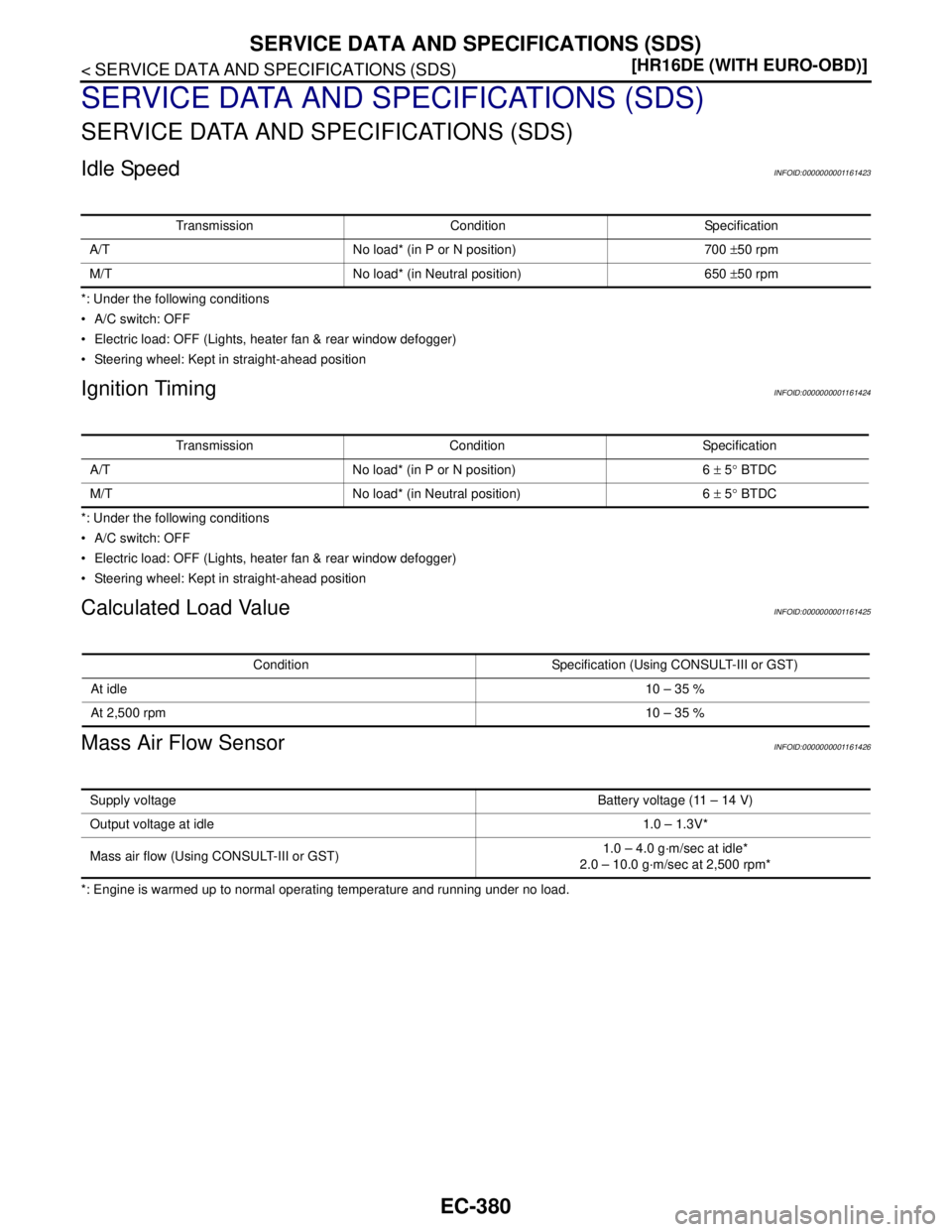
Idle SpeedINFOID:0000000001161423
*: Under the following conditions
A/C switch: OFF
Electric load: OFF (Lights, heater fan & rear window defogger)
Steering wheel: Kept in straight-ahead position
Ignition TimingINFOID:0000000001161424
*: Under the following conditions
A/C switch: OFF
Electric load: OFF (Lights, heater fan & rear window defogger)
Steering wheel: Kept in straight-ahead position
Calculated Load ValueINFOID:0000000001161425
Mass Air Flow SensorINFOID:0000000001161426
*: Engine is warmed up to normal operating temperature and running under no load.Transmission Condition Specification
A/T No load* (in P or N position) 700 ±50 rpm
M/T No load* (in Neutral position) 650 ±50 rpm
Transmission Condition Specification
A/T No load* (in P or N position) 6 ± 5° BTDC
M/T No load* (in Neutral position) 6 ± 5° BTDC
Condition Specification (Using CONSULT-III or GST)
At idle10 – 35 %
At 2,500 rpm10 – 35 %
Supply voltageBattery voltage (11 – 14 V)
Output voltage at idle1.0 – 1.3V*
Mass air flow (Using CONSULT-III or GST)1.0 – 4.0 g·m/sec at idle*
2.0 – 10.0 g·m/sec at 2,500 rpm*
Page 1748 of 5883
ENGINE CONTROL SYSTEM
EC-399
< FUNCTION DIAGNOSIS >[HR16DE (WITHOUT EURO-OBD)]
C
D
E
F
G
H
I
J
K
L
MA
EC
N
P O
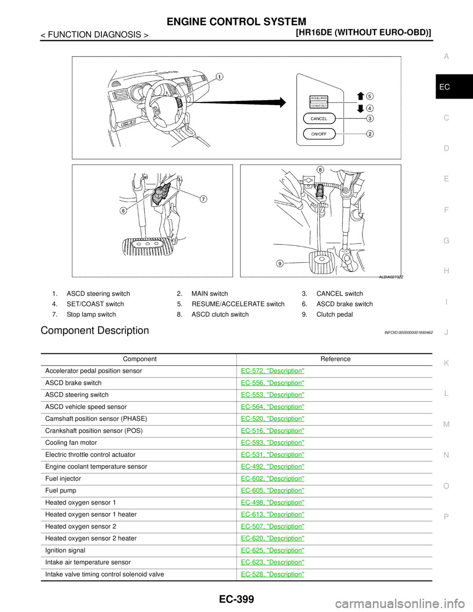
Component DescriptionINFOID:0000000001693462
1. ASCD steering switch 2. MAIN switch 3. CANCEL switch
4. SET/COAST switch 5. RESUME/ACCELERATE switch 6. ASCD brake switch
7. Stop lamp switch 8. ASCD clutch switch 9. Clutch pedal
ALBIA0273ZZ
Component Reference
Accelerator pedal position sensorEC-572, "
Description"
ASCD brake switchEC-556, "Description"
ASCD steering switchEC-553, "Description"
ASCD vehicle speed sensorEC-564, "Description"
Camshaft position sensor (PHASE)EC-520, "Description"
Crankshaft position sensor (POS)EC-516, "Description"
Cooling fan motorEC-593, "Description"
Electric throttle control actuatorEC-531, "Description"
Engine coolant temperature sensorEC-492, "Description"
Fuel injectorEC-602, "Description"
Fuel pumpEC-605, "Description"
Heated oxygen sensor 1EC-498, "Description"
Heated oxygen sensor 1 heaterEC-613, "Description"
Heated oxygen sensor 2EC-507, "Description"
Heated oxygen sensor 2 heaterEC-620, "Description"
Ignition signalEC-625, "Description"
Intake air temperature sensorEC-623, "Description"
Intake valve timing control solenoid valveEC-528, "Description"
Page 1812 of 5883
DIAGNOSIS SYSTEM (ECM)
EC-463
< FUNCTION DIAGNOSIS >[HR16DE (WITHOUT EURO-OBD)]
C
D
E
F
G
H
I
J
K
L
MA
EC
N
P O
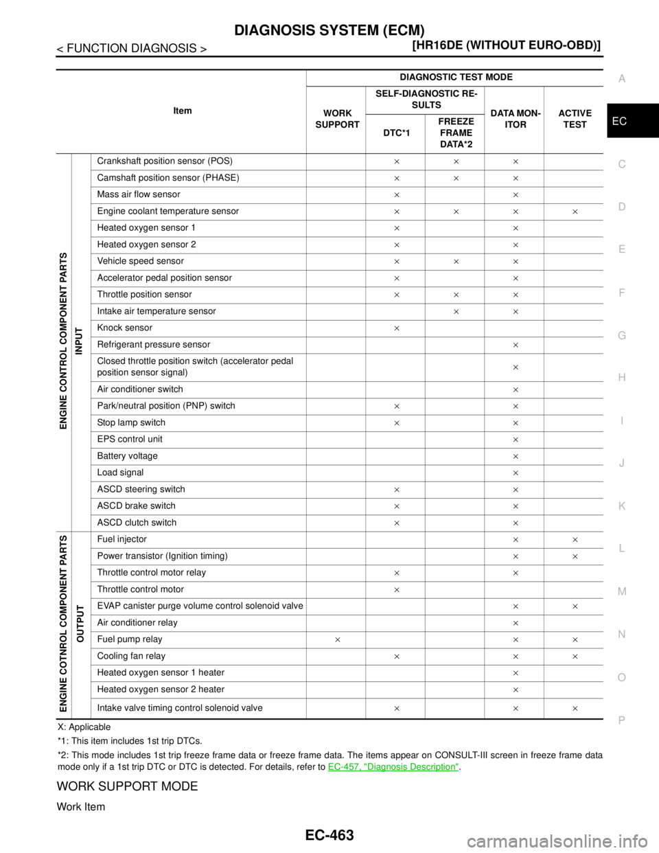
X: Applicable
*1: This item includes 1st trip DTCs.
*2: This mode includes 1st trip freeze frame data or freeze frame data. The items appear on CONSULT-III screen in freeze frame data
mode only if a 1st trip DTC or DTC is detected. For details, refer to EC-457, "
Diagnosis Description".
WORK SUPPORT MODE
Work Item
ItemDIAGNOSTIC TEST MODE
WORK
SUPPORTSELF-DIAGNOSTIC RE-
SULTS
DATA MON-
ITORACTIVE
TEST
DTC*1FREEZE
FRAME
DATA*2
ENGINE CONTROL COMPONENT PARTS
INPUT
Crankshaft position sensor (POS)×××
Camshaft position sensor (PHASE)×××
Mass air flow sensor××
Engine coolant temperature sensor××××
Heated oxygen sensor 1××
Heated oxygen sensor 2××
Vehicle speed sensor×××
Accelerator pedal position sensor××
Throttle position sensor×××
Intake air temperature sensor××
Knock sensor×
Refrigerant pressure sensor×
Closed throttle position switch (accelerator pedal
position sensor signal)×
Air conditioner switch×
Park/neutral position (PNP) switch××
Stop lamp switch××
EPS control unit×
Battery voltage×
Load signal×
ASCD steering switch××
ASCD brake switch××
ASCD clutch switch××
ENGINE COTNROL COMPONENT PARTS
OUTPUT
Fuel injector××
Power transistor (Ignition timing)××
Throttle control motor relay××
Throttle control motor×
EVAP canister purge volume control solenoid valve××
Air conditioner relay×
Fuel pump relay×××
Cooling fan relay×××
Heated oxygen sensor 1 heater×
Heated oxygen sensor 2 heater×
Intake valve timing control solenoid valve×××
Page 1815 of 5883
EC-466
< FUNCTION DIAGNOSIS >[HR16DE (WITHOUT EURO-OBD)]
DIAGNOSIS SYSTEM (ECM)
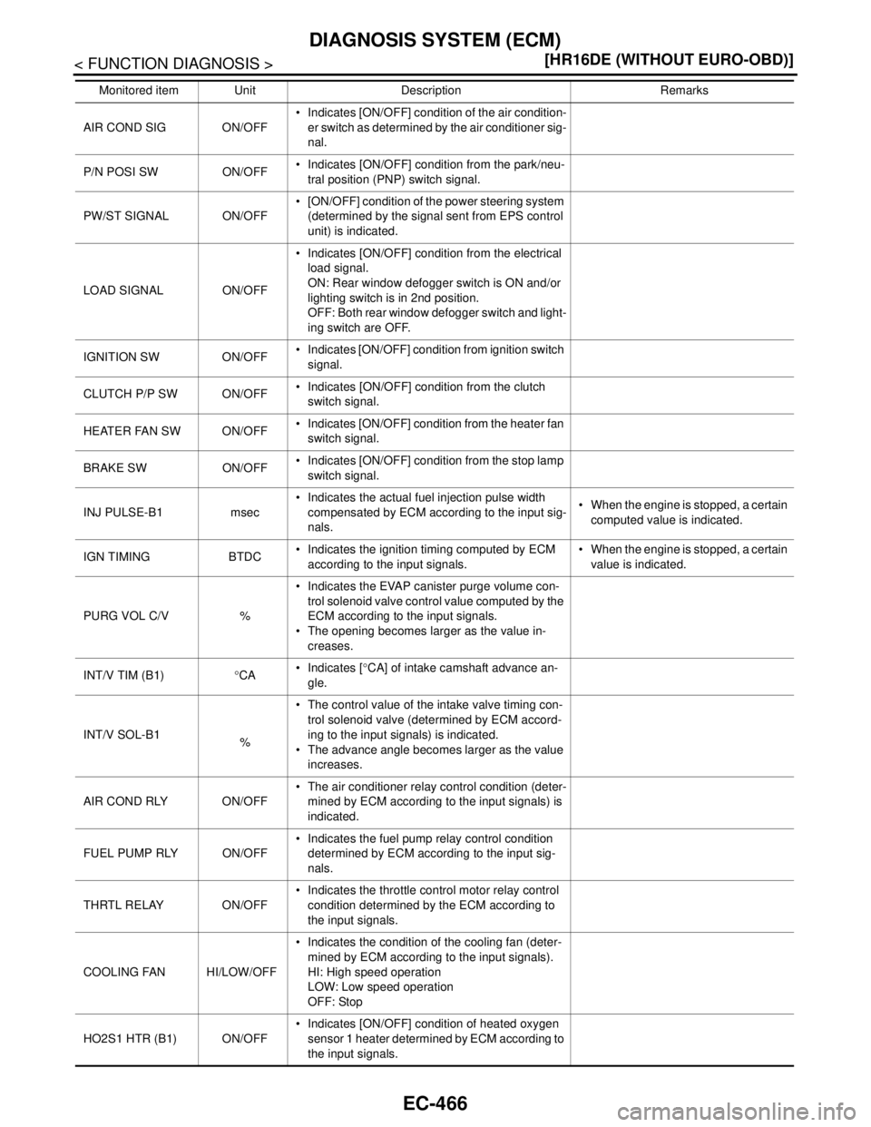
AIR COND SIG ON/OFF Indicates [ON/OFF] condition of the air condition-
er switch as determined by the air conditioner sig-
nal.
P/N POSI SW ON/OFF Indicates [ON/OFF] condition from the park/neu-
tral position (PNP) switch signal.
PW/ST SIGNAL ON/OFF [ON/OFF] condition of the power steering system
(determined by the signal sent from EPS control
unit) is indicated.
LOAD SIGNAL ON/OFF Indicates [ON/OFF] condition from the electrical
load signal.
ON: Rear window defogger switch is ON and/or
lighting switch is in 2nd position.
OFF: Both rear window defogger switch and light-
ing switch are OFF.
IGNITION SW ON/OFF Indicates [ON/OFF] condition from ignition switch
signal.
CLUTCH P/P SW ON/OFF Indicates [ON/OFF] condition from the clutch
switch signal.
HEATER FAN SW ON/OFF Indicates [ON/OFF] condition from the heater fan
switch signal.
BRAKE SW ON/OFF Indicates [ON/OFF] condition from the stop lamp
switch signal.
INJ PULSE-B1 msec Indicates the actual fuel injection pulse width
compensated by ECM according to the input sig-
nals. When the engine is stopped, a certain
computed value is indicated.
IGN TIMING BTDC Indicates the ignition timing computed by ECM
according to the input signals. When the engine is stopped, a certain
value is indicated.
PURG VOL C/V % Indicates the EVAP canister purge volume con-
trol solenoid valve control value computed by the
ECM according to the input signals.
The opening becomes larger as the value in-
creases.
INT/V TIM (B1)°CA Indicates [°CA] of intake camshaft advance an-
gle.
INT/V SOL-B1
% The control value of the intake valve timing con-
trol solenoid valve (determined by ECM accord-
ing to the input signals) is indicated.
The advance angle becomes larger as the value
increases.
AIR COND RLY ON/OFF The air conditioner relay control condition (deter-
mined by ECM according to the input signals) is
indicated.
FUEL PUMP RLY ON/OFF Indicates the fuel pump relay control condition
determined by ECM according to the input sig-
nals.
THRTL RELAY ON/OFF Indicates the throttle control motor relay control
condition determined by the ECM according to
the input signals.
COOLING FAN HI/LOW/OFF Indicates the condition of the cooling fan (deter-
mined by ECM according to the input signals).
HI: High speed operation
LOW: Low speed operation
OFF: Stop
HO2S1 HTR (B1) ON/OFF Indicates [ON/OFF] condition of heated oxygen
sensor 1 heater determined by ECM according to
the input signals. Monitored item Unit Description Remarks
Page 1816 of 5883
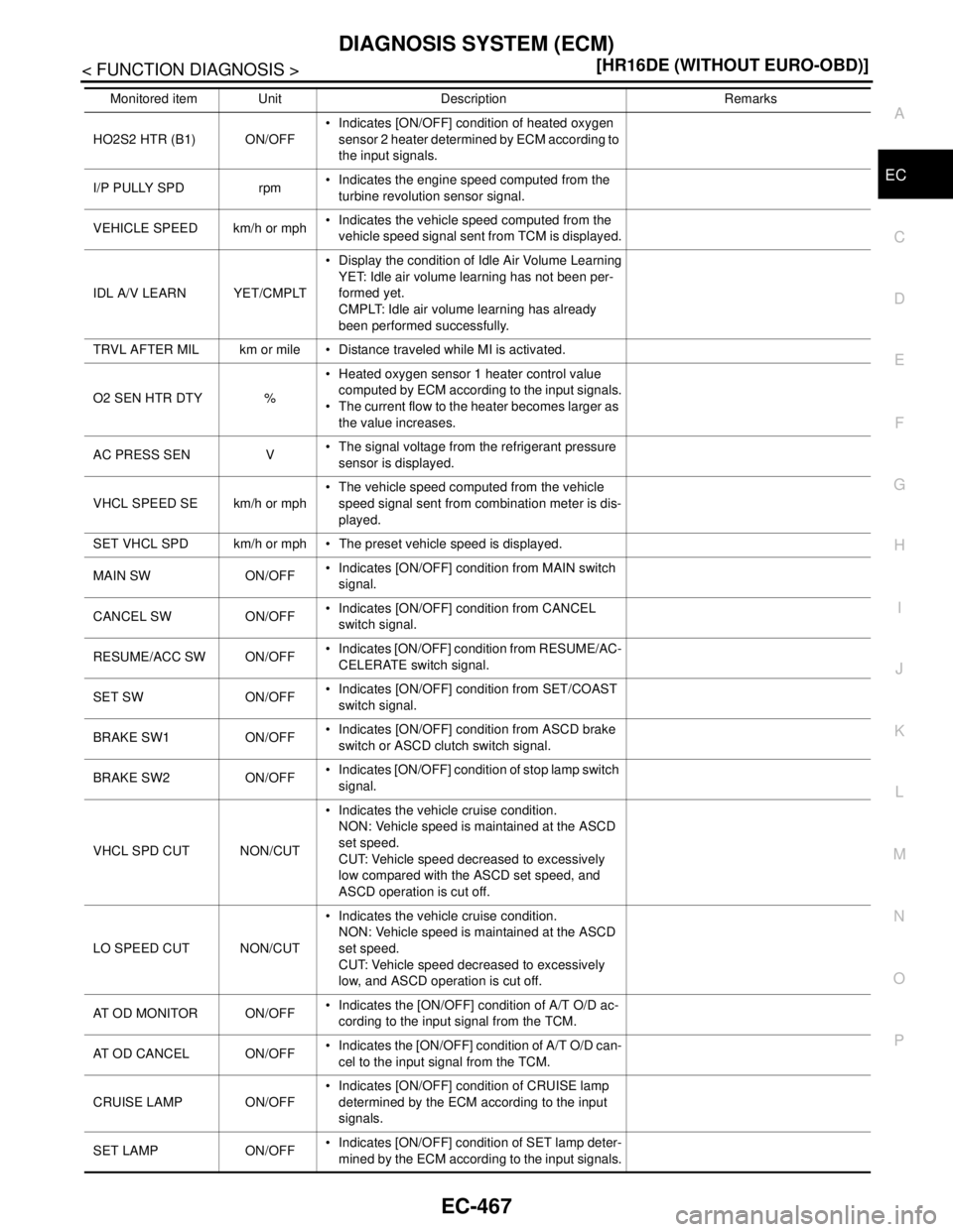
DIAGNOSIS SYSTEM (ECM)
EC-467
< FUNCTION DIAGNOSIS >[HR16DE (WITHOUT EURO-OBD)]
C
D
E
F
G
H
I
J
K
L
MA
EC
N
P O
HO2S2 HTR (B1) ON/OFF Indicates [ON/OFF] condition of heated oxygen
sensor 2 heater determined by ECM according to
the input signals.
I/P PULLY SPD rpm Indicates the engine speed computed from the
turbine revolution sensor signal.
VEHICLE SPEED km/h or mph Indicates the vehicle speed computed from the
vehicle speed signal sent from TCM is displayed.
IDL A/V LEARN YET/CMPLT Display the condition of Idle Air Volume Learning
YET: Idle air volume learning has not been per-
formed yet.
CMPLT: Idle air volume learning has already
been performed successfully.
TRVL AFTER MIL km or mile Distance traveled while MI is activated.
O2 SEN HTR DTY % Heated oxygen sensor 1 heater control value
computed by ECM according to the input signals.
The current flow to the heater becomes larger as
the value increases.
AC PRESS SEN V The signal voltage from the refrigerant pressure
sensor is displayed.
VHCL SPEED SE km/h or mph The vehicle speed computed from the vehicle
speed signal sent from combination meter is dis-
played.
SET VHCL SPD km/h or mph The preset vehicle speed is displayed.
MAIN SW ON/OFF Indicates [ON/OFF] condition from MAIN switch
signal.
CANCEL SW ON/OFF Indicates [ON/OFF] condition from CANCEL
switch signal.
RESUME/ACC SW ON/OFF Indicates [ON/OFF] condition from RESUME/AC-
CELERATE switch signal.
SET SW ON/OFF Indicates [ON/OFF] condition from SET/COAST
switch signal.
BRAKE SW1 ON/OFF Indicates [ON/OFF] condition from ASCD brake
switch or ASCD clutch switch signal.
BRAKE SW2 ON/OFF Indicates [ON/OFF] condition of stop lamp switch
signal.
VHCL SPD CUT NON/CUT Indicates the vehicle cruise condition.
NON: Vehicle speed is maintained at the ASCD
set speed.
CUT: Vehicle speed decreased to excessively
low compared with the ASCD set speed, and
ASCD operation is cut off.
LO SPEED CUT NON/CUT Indicates the vehicle cruise condition.
NON: Vehicle speed is maintained at the ASCD
set speed.
CUT: Vehicle speed decreased to excessively
low, and ASCD operation is cut off.
AT O D M O N I TO R O N / O F F Indicates the [ON/OFF] condition of A/T O/D ac-
cording to the input signal from the TCM.
AT OD CANCEL ON/OFF Indicates the [ON/OFF] condition of A/T O/D can-
cel to the input signal from the TCM.
CRUISE LAMP ON/OFF Indicates [ON/OFF] condition of CRUISE lamp
determined by the ECM according to the input
signals.
SET LAMP ON/OFF Indicates [ON/OFF] condition of SET lamp deter-
mined by the ECM according to the input signals. Monitored item Unit Description Remarks
Page 1946 of 5883
ELECTRICAL LOAD SIGNAL
EC-597
< COMPONENT DIAGNOSIS >[HR16DE (WITHOUT EURO-OBD)]
C
D
E
F
G
H
I
J
K
L
MA
EC
N
P O
ELECTRICAL LOAD SIGNAL
DescriptionINFOID:0000000001693428
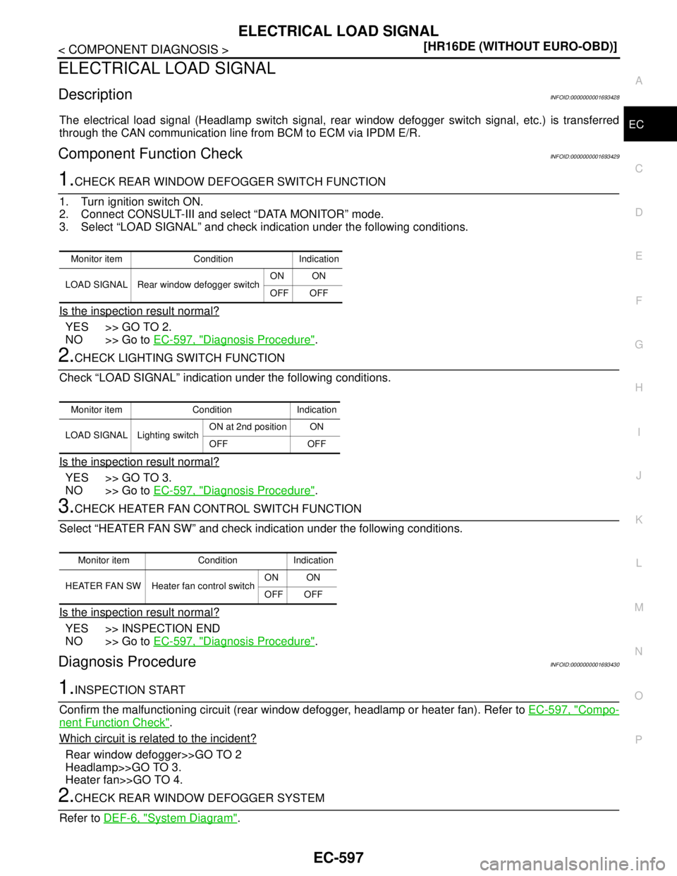
The electrical load signal (Headlamp switch signal, rear window defogger switch signal, etc.) is transferred
through the CAN communication line from BCM to ECM via IPDM E/R.
Component Function CheckINFOID:0000000001693429
1.CHECK REAR WINDOW DEFOGGER SWITCH FUNCTION
1. Turn ignition switch ON.
2. Connect CONSULT-III and select “DATA MONITOR” mode.
3. Select “LOAD SIGNAL” and check indication under the following conditions.
Is the inspection result normal?
YES >> GO TO 2.
NO >> Go to EC-597, "
Diagnosis Procedure".
2.CHECK LIGHTING SWITCH FUNCTION
Check “LOAD SIGNAL” indication under the following conditions.
Is the inspection result normal?
YES >> GO TO 3.
NO >> Go to EC-597, "
Diagnosis Procedure".
3.CHECK HEATER FAN CONTROL SWITCH FUNCTION
Select “HEATER FAN SW” and check indication under the following conditions.
Is the inspection result normal?
YES >> INSPECTION END
NO >> Go to EC-597, "
Diagnosis Procedure".
Diagnosis ProcedureINFOID:0000000001693430
1.INSPECTION START
Confirm the malfunctioning circuit (rear window defogger, headlamp or heater fan). Refer to EC-597, "
Compo-
nent Function Check".
Which circuit is related to the incident?
Rear window defogger>>GO TO 2
Headlamp>>GO TO 3.
Heater fan>>GO TO 4.
2.CHECK REAR WINDOW DEFOGGER SYSTEM
Refer to DEF-6, "
System Diagram".
Monitor item Condition Indication
LOAD SIGNAL Rear window defogger switchON ON
OFF OFF
Monitor item Condition Indication
LOAD SIGNAL Lighting switchON at 2nd position ON
OFF OFF
Monitor item Condition Indication
HEATER FAN SW Heater fan control switchON ON
OFF OFF
Page 1947 of 5883
EC-598
< COMPONENT DIAGNOSIS >[HR16DE (WITHOUT EURO-OBD)]
ELECTRICAL LOAD SIGNAL
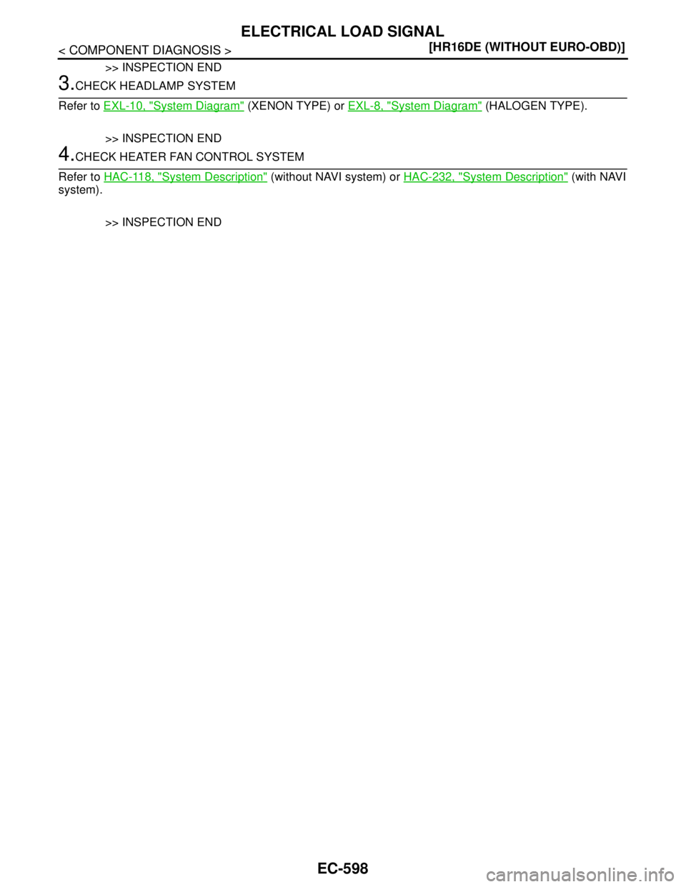
>> INSPECTION END
3.CHECK HEADLAMP SYSTEM
Refer to EXL-10, "
System Diagram" (XENON TYPE) or EXL-8, "System Diagram" (HALOGEN TYPE).
>> INSPECTION END
4.CHECK HEATER FAN CONTROL SYSTEM
Refer to HAC-118, "
System Description" (without NAVI system) or HAC-232, "System Description" (with NAVI
system).
>> INSPECTION END
Page 1962 of 5883
HO2S1 HEATER
EC-613
< COMPONENT DIAGNOSIS >[HR16DE (WITHOUT EURO-OBD)]
C
D
E
F
G
H
I
J
K
L
MA
EC
N
P O
HO2S1 HEATER
DescriptionINFOID:0000000001697495
SYSTEM DESCRIPTION
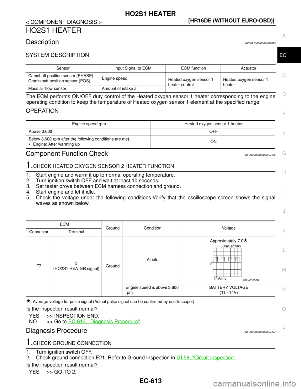
The ECM performs ON/OFF duty control of the Heated oxygen sensor 1 heater corresponding to the engine
operating condition to keep the temperature of Heated oxygen sensor 1 element at the specified range.
OPERATION
Component Function CheckINFOID:0000000001697496
1.CHECK HEATED OXYGEN SENSOR 2 HEATER FUNCTION
1. Start engine and warm it up to normal operating temperature.
2. Turn ignition switch OFF and wait at least 10 seconds.
3. Set tester prove between ECM harness connection and ground.
4. Start engine and let it idle.
5. Check the voltage under the following conditions.Verify that the oscilloscope screen shows the signal
waves as shown below.
: Average voltage for pulse signal (Actual pulse signal can be confirmed by oscilloscope.)
Is the inspection result normal?
YES >> INSPECTION END.
NO >> Go to EC-613, "
Diagnosis Procedure".
Diagnosis ProcedureINFOID:0000000001697497
1.CHECK GROUND CONNECTION
1. Turn ignition switch OFF.
2. Check ground connection E21. Refer to Ground Inspection in GI-58, "
Circuit Inspection".
Is the inspection result normal?
YES >> GO TO 2.
Sensor Input Signal to ECM ECM function Actuator
Camshaft position sensor (PHASE)
Crankshaft position sensor (POS)Engine speed
Heated oxygen sensor 1
heater controlHeated oxygen sensor 1
heater
Mass air flow sensor Amount of intake air
Engine speed rpm Heated oxygen sensor 1 heater
Above 3,600OFF
Below 3,600 rpm after the following conditions are met.
Engine: After warming upON
ECM
Ground Condition Voltage
Connector Terminal
F73
(HO2S1 HEATER signal)GroundAt idleApproximately 7.0
Engine speed is above 3,600
rpmBATTERY VOLTAGE
(11 - 14V)
JMBIA0325GB
Page 1963 of 5883
EC-614
< COMPONENT DIAGNOSIS >[HR16DE (WITHOUT EURO-OBD)]
HO2S1 HEATER
NO >> Repair or replace ground connection.
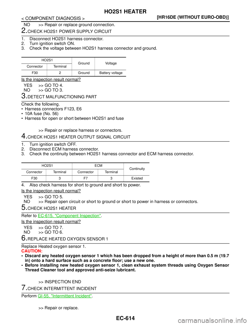
2.CHECK HO2S1 POWER SUPPLY CIRCUIT
1. Disconnect HO2S1 harness connector.
2. Turn ignition switch ON.
3. Check the voltage between HO2S1 harness connector and ground.
Is the inspection result normal?
YES >> GO TO 4.
NO >> GO TO 3.
3.DETECT MALFUNCTIONING PART
Check the following.
Harness connectors F123, E6
10A fuse (No. 56)
Harness for open or short between HO2S1 and fuse
>> Repair or replace harness or connectors.
4.CHECK HO2S1 HEATER OUTPUT SIGNAL CIRCUIT
1. Turn ignition switch OFF.
2. Disconnect ECM harness connector.
3. Check the continuity between HO2S1 harness connector and ECM harness connector.
4. Also check harness for short to ground and short to power.
Is the inspection result normal?
YES >> GO TO 5.
NO >> Repair open circuit or short to ground or short to power in harness or connectors.
5.CHECK HO2S1 HEATER
Refer to EC-615, "
Component Inspection".
Is the inspection result normal?
YES >> GO TO 7.
NO >> GO TO 6.
6.REPLACE HEATED OXYGEN SENSOR 1
Replace Heated oxygen sensor 1.
CAUTION:
Discard any heated oxygen sensor 1 which has been dropped from a height of more than 0.5 m (19.7
in) onto a hard surface such as a concrete floor; use a new one.
Before installing new heated oxygen sensor 1, clean exhaust system threads using Oxygen Sensor
Thread Cleaner tool and approved anti-seize lubricant.
>> INSPECTION END
7.CHECK INTERMITTENT INCIDENT
Perform GI-55, "
Intermittent Incident".
>> Repair or replace.
HO2S1
Ground Voltage
Connector Terminal
F30 2 Ground Battery voltage
HO2S1 ECM
Continuity
Connector Terminal Connector Terminal
F30 3 F7 3 Existed
Page 1964 of 5883
HO2S1 HEATER
EC-615
< COMPONENT DIAGNOSIS >[HR16DE (WITHOUT EURO-OBD)]
C
D
E
F
G
H
I
J
K
L
MA
EC
N
P O
Component InspectionINFOID:0000000001697498
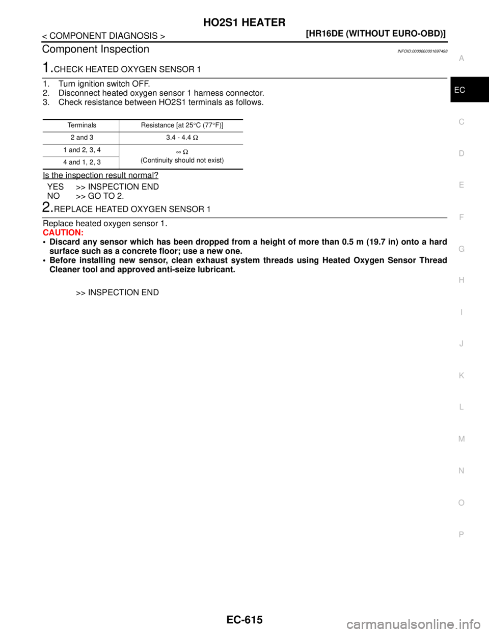
1.CHECK HEATED OXYGEN SENSOR 1
1. Turn ignition switch OFF.
2. Disconnect heated oxygen sensor 1 harness connector.
3. Check resistance between HO2S1 terminals as follows.
Is the inspection result normal?
YES >> INSPECTION END
NO >> GO TO 2.
2.REPLACE HEATED OXYGEN SENSOR 1
Replace heated oxygen sensor 1.
CAUTION:
Discard any sensor which has been dropped from a height of more than 0.5 m (19.7 in) onto a hard
surface such as a concrete floor; use a new one.
Before installing new sensor, clean exhaust system threads using Heated Oxygen Sensor Thread
Cleaner tool and approved anti-seize lubricant.
>> INSPECTION END
Terminals Resistance [at 25°C (77°F)]
2 and 3 3.4 - 4.4 Ω
1 and 2, 3, 4
∞ Ω
(Continuity should not exist)
4 and 1, 2, 3