Oil NISSAN TIIDA 2007 Service User Guide
[x] Cancel search | Manufacturer: NISSAN, Model Year: 2007, Model line: TIIDA, Model: NISSAN TIIDA 2007Pages: 5883, PDF Size: 78.95 MB
Page 229 of 5883
REAR DISC BRAKE
BR-37
< DISASSEMBLY AND ASSEMBLY >
C
D
E
G
H
I
J
K
L
MA
B
BR
N
O
P
REAR DISC BRAKE
Disassembly and AssemblyINFOID:0000000001724669
DISASSEMBLY
1. Remove the sliding pin bolt, and then remove the pad, shim, shim cover, and pad retainer from the torque
member and cylinder.
2. Remove sliding pin boot from torque member.
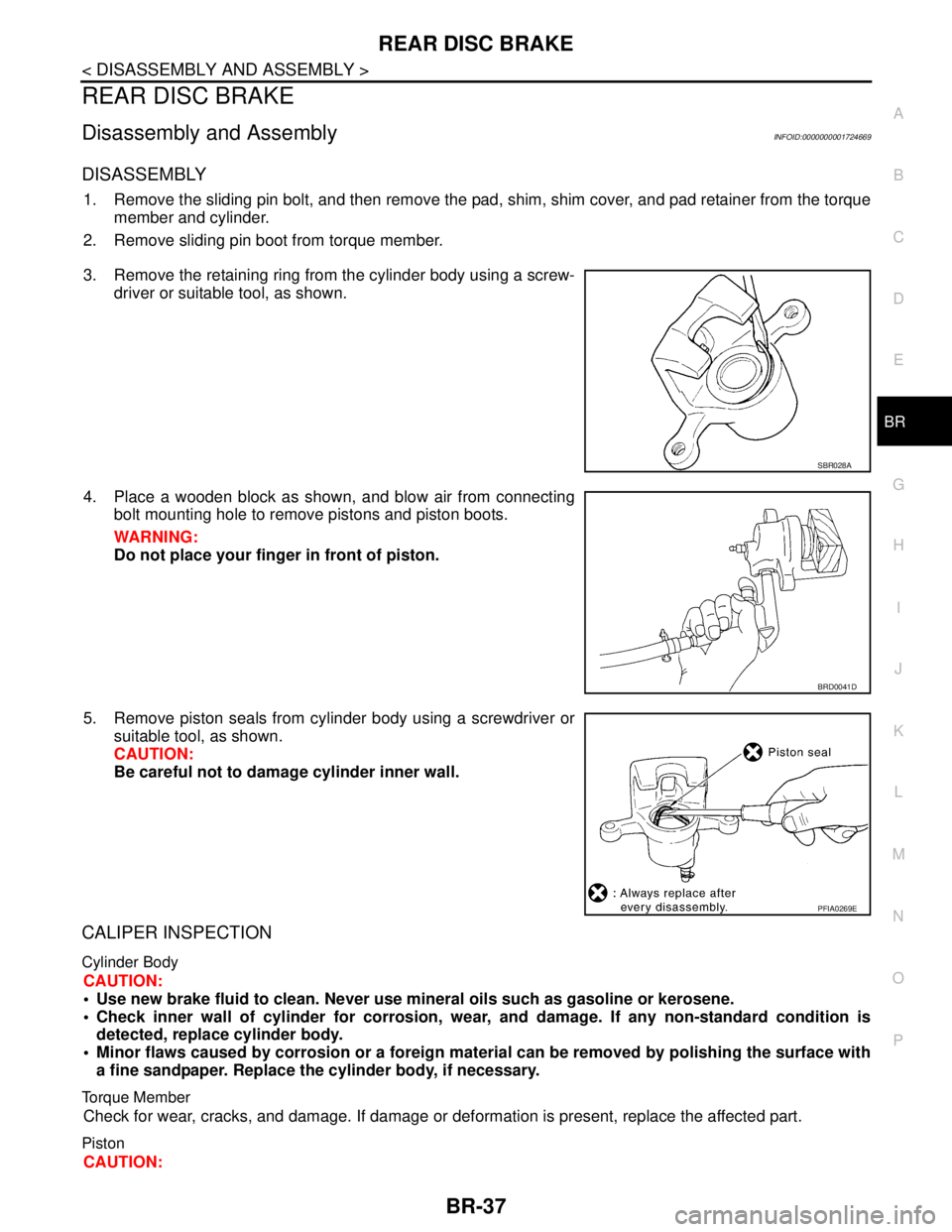
3. Remove the retaining ring from the cylinder body using a screw-
driver or suitable tool, as shown.
4. Place a wooden block as shown, and blow air from connecting
bolt mounting hole to remove pistons and piston boots.
WARNING:
Do not place your finger in front of piston.
5. Remove piston seals from cylinder body using a screwdriver or
suitable tool, as shown.
CAUTION:
Be careful not to damage cylinder inner wall.
CALIPER INSPECTION
Cylinder Body
CAUTION:
Use new brake fluid to clean. Never use mineral oils such as gasoline or kerosene.
Check inner wall of cylinder for corrosion, wear, and damage. If any non-standard condition is
detected, replace cylinder body.
Minor flaws caused by corrosion or a foreign material can be removed by polishing the surface with
a fine sandpaper. Replace the cylinder body, if necessary.
Torque Member
Check for wear, cracks, and damage. If damage or deformation is present, replace the affected part.
Piston
CAUTION:
SBR028A
BRD0041D
PFIA0269E
Page 313 of 5883

BRC-80
< PRECAUTION >[ABS]
PRECAUTIONS
PRECAUTION
PRECAUTIONS
Precaution for Supplemental Restraint System (SRS) "AIR BAG" and "SEAT BELT
PRE-TENSIONER"
INFOID:0000000001691368
The Supplemental Restraint System such as “AIR BAG” and “SEAT BELT PRE-TENSIONER”, used along
with a front seat belt, helps to reduce the risk or severity of injury to the driver and front passenger for certain
types of collision. Information necessary to service the system safely is included in the SRS and SB section of
this Service Manual.
WARNING:
To avoid rendering the SRS inoperative, which could increase the risk of personal injury or death in
the event of a collision which would result in air bag inflation, all maintenance must be performed by
an authorized NISSAN/INFINITI dealer.
Improper maintenance, including incorrect removal and installation of the SRS, can lead to personal
injury caused by unintentional activation of the system. For removal of Spiral Cable and Air Bag
Module, see the SRS section.
Do not use electrical test equipment on any circuit related to the SRS unless instructed to in this
Service Manual. SRS wiring harnesses can be identified by yellow and/or orange harness connec-
tors.
Precaution for Brake SystemINFOID:0000000001691369
Recommended fluid is Genuine NISSAN Fluid, DOT 3 or DOT 4 (US FMVSS No. 116).
Do not reuse the drained brake fluid.
Be careful not to splash brake fluid on painted areas such as body. If brake fluid is splashed, wipe it off and
flush area with water immediately.
Do not use mineral oils such as gasoline or kerosene to clean. They will ruin rubber parts and cause
improper operation.
Using a flare nut torque wrench, securely tighten brake tube flare
nuts.
Brake system is an important safety part. If a brake fluid leak is
detected, always disassemble malfunctioning parts. If any mal-
functioning part is found, replace the part with a new one.
Before working, turn ignition switch OFF and disconnect connec-
tors for ABS actuator and electric unit or battery terminals.
When installing brake piping, be sure to check tightening torque.
Precaution for Brake ControlINFOID:0000000001691370
During ABS operation, brake pedal lightly vibrates and a mechanical noise may be heard. This is normal.
When starting engine, or just after starting vehicle, brake pedal may vibrate or motor operating noise may be
heard from engine compartment. This is a normal status of operation check.
Stopping distance may be longer than that of vehicles without ABS when vehicle drives on rough, gravel, or
snow-covered (fresh, deep snow) roads.
When an error is indicated by ABS or another warning lamp, collect all necessary information from the cus-
tomer (what symptoms are present under what conditions) and check for simple causes before starting diag-
nostic servicing. Besides the electrical system inspection, check booster operation, brake fluid level, and oil
leaks.
If tyre size and type are used in an improper combination, or brake pads are not Genuine Nissan parts, stop-
ping distance or steering stability may deteriorate.
If there is a radio, antenna, or antenna lead-in wire (including wiring) near the control unit, ABS system may
malfunction or return an error.
If aftermarket parts (e.g. car stereo equipment, CD player) have been installed, check electrical harnesses
for pinches, open, and improper wiring.
SBR820BA
Page 412 of 5883

PRECAUTIONS
BRC-179
< PRECAUTION >[ESP/TCS/ABS]
C
D
E
G
H
I
J
K
L
MA
B
BRC
N
O
P
PRECAUTION
PRECAUTIONS
Precaution for Supplemental Restraint System (SRS) "AIR BAG" and "SEAT BELT
PRE-TENSIONER"
INFOID:0000000001691411
The Supplemental Restraint System such as “AIR BAG” and “SEAT BELT PRE-TENSIONER”, used along
with a front seat belt, helps to reduce the risk or severity of injury to the driver and front passenger for certain
types of collision. Information necessary to service the system safely is included in the SRS and SB section of
this Service Manual.
WARNING:
To avoid rendering the SRS inoperative, which could increase the risk of personal injury or death in
the event of a collision which would result in air bag inflation, all maintenance must be performed by
an authorized NISSAN/INFINITI dealer.
Improper maintenance, including incorrect removal and installation of the SRS, can lead to personal
injury caused by unintentional activation of the system. For removal of Spiral Cable and Air Bag
Module, see the SRS section.
Do not use electrical test equipment on any circuit related to the SRS unless instructed to in this
Service Manual. SRS wiring harnesses can be identified by yellow and/or orange harnesses or har-
ness connectors.
Precaution for Brake SystemINFOID:0000000001691412
Recommended fluid is Genuine NISSAN Fluid, DOT 3 or DOT 4 (US FMVSS No. 116).
Do not reuse drained brake fluid.
Be careful not to splash brake fluid on painted areas such as body. If brake fluid is splashed, wipe it off and
flush area with water immediately.
Do not use mineral oils such as gasoline or kerosene to clean. They will ruin rubber parts and cause
improper operation.
Using a flare nut torque wrench, securely tighten brake tube flare
nuts.
Brake system is an important safety part. If a brake fluid leak is
detected, always disassemble the affected part. If a malfunction is
detected, replace part with a new one.
Before working, turn ignition switch OFF and disconnect electrical
connectors of ABS actuator and electric unit (control unit) or bat-
tery negative terminals.
When installing brake piping, be sure to check torque.
After removing/installing any hydraulic parts of the brake or ESP
system (such as actuator and piping parts, etc), bleed air from the
system.
Precaution for Brake ControlINFOID:0000000001691413
During ESP/TCS/ABS operation, brake pedal lightly vibrates and a mechanical noise may be heard. This is
normal.
When starting engine, or just after starting vehicle, brake pedal may vibrate or motor operating noise may be
heard from engine room. This is a normal status of operation check.
Stopping distance may be longer than that of vehicles without ABS when vehicle drives on rough, gravel, or
snow-covered (fresh, deep snow) roads.
When an error is indicated by ABS or another warning lamp, collect all necessary information from the cus-
tomer (what symptoms are present under what conditions) and check for simple causes before starting diag-
nostic servicing. Besides the electrical system inspection, check booster operation, brake fluid level, and
fluid leaks.
If tire size and type are used in an improper combination, or brake pads are not Genuine NISSAN parts,
stopping distance or steering stability may deteriorate.
If there is a radio, antenna, or antenna lead-in wire (including wiring) near control module, ESP/TCS/ABS
function may have a malfunction or error.
If aftermarket parts (car stereo, CD player, etc.) have been installed, check for incidents such as harness
pinches, open circuits, and improper wiring.
SBR820BA
Page 437 of 5883

CHG-16
< SERVICE DATA AND SPECIFICATIONS (SDS) [HR16DE]
SERVICE DATA AND SPECIFICATIONS (SDS)
SERVICE DATA AND SPECIFICATIONS (SDS)
SERVICE DATA AND SPECIFICATIONS (SDS)
GeneratorINFOID:0000000001689489
Applied modelHR16DE
Ty p eA2TJ0291ZE
MITSUBISHI
Nominal rating [V - A] 12 - 120
Ground polarityNegative
Minimum revolution under no-load (When 13.5
V is applied)[rpm] Less than 1,300
Hot output current (When 13.5 V is applied) [A/rpm]More than 27/1,300
More than 95/2,500
More than 116/5,000
Regulated output voltage [V] 14.1 - 14.7
Minimum length of brush [mm (in)] More than 5.00 (0.197)
Brush spring pressure [N (g, oz)] 4.1 - 5.3 (418 - 541, 14.7 - 19.1)
Slip ring minimum outer diameter [mm (in)] More than 22.1 (0.870)
Rotor (Field coil) resistance [Ω] 1.7 - 2.2
Page 451 of 5883

CHG-30
< SERVICE DATA AND SPECIFICATIONS (SDS) [MR18DE]
SERVICE DATA AND SPECIFICATIONS (SDS)
SERVICE DATA AND SPECIFICATIONS (SDS)
SERVICE DATA AND SPECIFICATIONS (SDS)
GeneratorINFOID:0000000001690788
Ty p eH90-128SC
MITSUBISHI make
Nominal rating12 V - 90 A
Ground polarityNegative
Minimum revolution under no-load (when 13.5 V is applied) Less than 1,200 rpm
Hot output current (when 13.5 V is applied)More than 27 A/1,300 rpm
More than 76 A/2,500 rpm
More than 85 A/5,000 rpm
Regulated output voltage14.1 - 14.7 V
Minimum length of brush More than 6.00 mm (0.236 in)
Brush spring pressure 1.1 - 3.7 N (112 - 378 g, 4.00 - 13.3 oz)
Slip ring minimum outer diameter More than 14.7 mm (0.579 in)
Rotor (field coil) resistance 1.61 - 1.91 Ω
Page 465 of 5883

CHG-44
< SERVICE DATA AND SPECIFICATIONS (SDS) [K9K]
SERVICE DATA AND SPECIFICATIONS (SDS)
SERVICE DATA AND SPECIFICATIONS (SDS)
SERVICE DATA AND SPECIFICATIONS (SDS)
GeneratorINFOID:0000000001691231
Applied modelK9K
Ty p e0 124 525 082
BOSCH make
Nominal rating [V - A] —
Ground polarity—
Minimum revolution under no-load (When 13.5 V
is applied)[rpm] —
Hot output current (When 13.5 V is applied) [A/rpm] —
Regulated output voltage [V] —
Minimum length of brush [mm (in)] —
Brush spring pressure [N (g, oz)] —
Slip ring minimum outer diameter [mm (in)] —
Rotor (Field coil) resistance [Ω]—
Page 467 of 5883
CL-2
< SERVICE INFORMATION >
PRECAUTIONS
SERVICE INFORMATION
PRECAUTIONS
Precaution for Supplemental Restraint System (SRS) "AIR BAG" and "SEAT BELT
PRE-TENSIONER"
INFOID:0000000001375288
The Supplemental Restraint System such as “AIR BAG” and “SEAT BELT PRE-TENSIONER”, used along
with a front seat belt, helps to reduce the risk or severity of injury to the driver and front passenger for certain
types of collision. This system includes seat belt switch inputs and dual stage front air bag modules. The SRS
system uses the seat belt switches to determine the front air bag deployment, and may only deploy one front
air bag, depending on the severity of a collision and whether the front occupants are belted or unbelted.
Information necessary to service the system safely is included in the SRS and SB section of this Service Man-
ual.
WARNING:
• To avoid rendering the SRS inoperative, which could increase the risk of personal injury or death in
the event of a collision which would result in air bag inflation, all maintenance must be performed by
an authorized NISSAN/INFINITI dealer.
Improper maintenance, including incorrect removal and installation of the SRS, can lead to personal
injury caused by unintentional activation of the system. For removal of Spiral Cable and Air Bag
Module, see the SRS section.
Do not use electrical test equipment on any circuit related to the SRS unless instructed to in this
Service Manual. SRS wiring harnesses can be identified by yellow and/or orange harnesses or har-
ness connectors.
Service Notice or PrecautionINFOID:0000000001375289
Use recommended brake fluid when adding fluid to the clutch reservoir tank. Refer to MA-19, "Fluids
and Lubricants".
Do not reuse fluid drained from clutch system.
Do not splash brake fluid on painted areas.
Use new brake fluid to clean or wash all parts of master cylinder and operating cylinder.
Do not use mineral oils such as gasoline or kerosene. It will ruin the rubber parts of the hydraulic
system.
If transaxle assembly is removed from the vehicle, always replace CSC (Concentric slave cylinder).
Return CSC to original position to remove transaxle assembly. Dust on clutch disc sliding parts may
damage CSC seal and may cause clutch fluid leakage.
Do not disassemble clutch master cylinder and CSC.
WARNING:
After cleaning clutch disc, clean it with a dust collector. Do not use compressed air.
Page 469 of 5883
CL-4
< SERVICE INFORMATION >
NOISE, VIBRATION AND HARSHNESS (NVH) TROUBLESHOOTING
NOISE, VIBRATION AND HARSHNESS (NVH) TROUBLESHOOTING
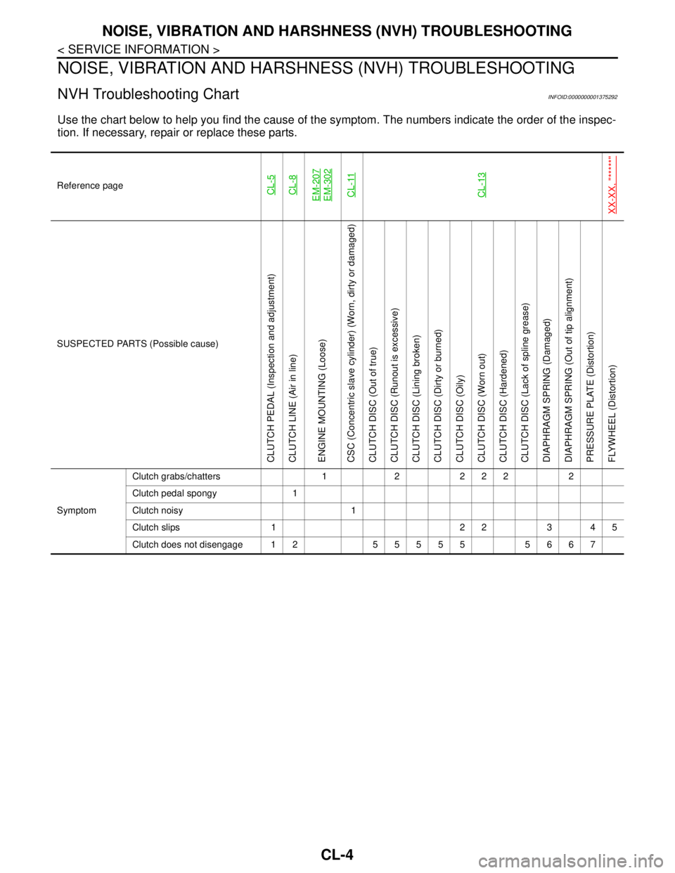
NVH Troubleshooting ChartINFOID:0000000001375292
Use the chart below to help you find the cause of the symptom. The numbers indicate the order of the inspec-
tion. If necessary, repair or replace these parts.
Reference pageCL-5CL-8EM-207EM-302CL-11CL-13
XX-XX, "*****"
SUSPECTED PARTS (Possible cause)
CLUTCH PEDAL (Inspection and adjustment)
CLUTCH LINE (Air in line)
ENGINE MOUNTING (Loose)
CSC (Concentric slave cylinder) (Worn, dirty or damaged)
CLUTCH DISC (Out of true)
CLUTCH DISC (Runout is excessive)
CLUTCH DISC (Lining broken)
CLUTCH DISC (Dirty or burned)
CLUTCH DISC (Oily)
CLUTCH DISC (Worn out)
CLUTCH DISC (Hardened)
CLUTCH DISC (Lack of spline grease)
DIAPHRAGM SPRING (Damaged)
DIAPHRAGM SPRING (Out of tip alignment)
PRESSURE PLATE (Distortion)
FLYWHEEL (Distortion)
SymptomClutch grabs/chatters 1 2 2 2 2 2
Clutch pedal spongy 1
Clutch noisy 1
Clutch slips 1 2 2 3 4 5
Clutch does not disengage 12 55555 5667
Page 478 of 5883
CLUTCH DISC, CLUTCH COVER AND FLYWHEEL
CL-13
< SERVICE INFORMATION >
C
E
F
G
H
I
J
K
L
MA
B
CL
N
O
P
CLUTCH DISC, CLUTCH COVER AND FLYWHEEL
Removal and InstallationINFOID:0000000001375299
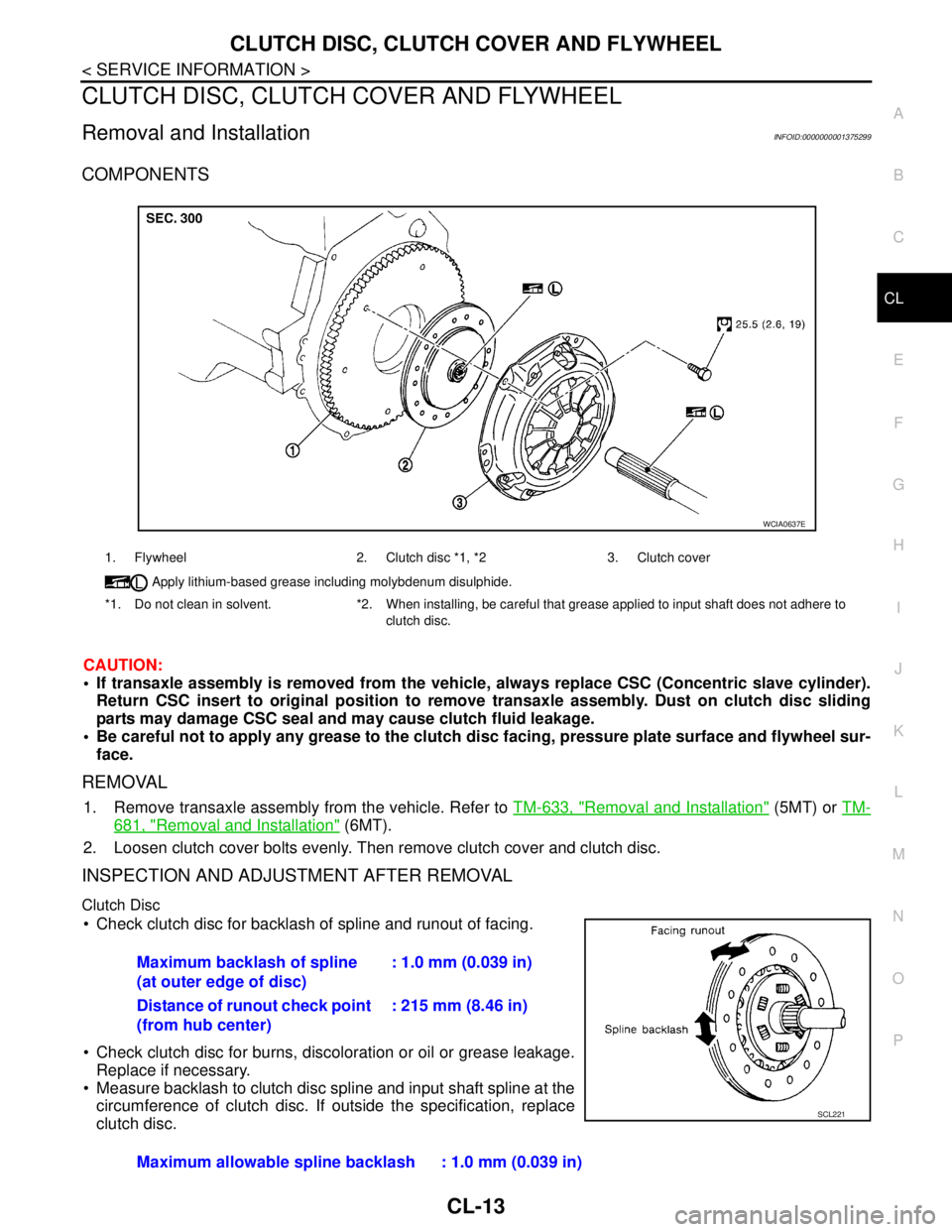
COMPONENTS
CAUTION:
If transaxle assembly is removed from the vehicle, always replace CSC (Concentric slave cylinder).
Return CSC insert to original position to remove transaxle assembly. Dust on clutch disc sliding
parts may damage CSC seal and may cause clutch fluid leakage.
Be careful not to apply any grease to the clutch disc facing, pressure plate surface and flywheel sur-
face.
REMOVAL
1. Remove transaxle assembly from the vehicle. Refer to TM-633, "Removal and Installation" (5MT) or TM-
681, "Removal and Installation" (6MT).
2. Loosen clutch cover bolts evenly. Then remove clutch cover and clutch disc.
INSPECTION AND ADJUSTMENT AFTER REMOVAL
Clutch Disc
Check clutch disc for backlash of spline and runout of facing.
Check clutch disc for burns, discoloration or oil or grease leakage.
Replace if necessary.
Measure backlash to clutch disc spline and input shaft spline at the
circumference of clutch disc. If outside the specification, replace
clutch disc.
1. Flywheel 2. Clutch disc *1, *2 3. Clutch cover
Apply lithium-based grease including molybdenum disulphide.
*1. Do not clean in solvent. *2. When installing, be careful that grease applied to input shaft does not adhere to
clutch disc.
WCIA0637E
Maximum backlash of spline
(at outer edge of disc): 1.0 mm (0.039 in)
Distance of runout check point
(from hub center): 215 mm (8.46 in)
Maximum allowable spline backlash : 1.0 mm (0.039 in)
SCL221
Page 490 of 5883

PRECAUTIONS
CO-9
< PRECAUTION >[HR16DE]
C
D
E
F
G
H
I
J
K
L
MA
CO
N
P O
CAUTION:
Be careful not to damage the mating surfaces.
Tap Tool to insert it (1), and then slide it by tapping on the side (2)
as shown.
In areas where Tool is difficult to use, use plastic hammer to lightly
tap the parts, to remove it.
CAUTION:
If for some unavoidable reason suitable tool such as screw-
driver is used, be careful not to damage the mating surfaces.
LIQUID GASKET APPLICATION PROCEDURE
1. Remove old liquid gasket adhering to the liquid gasket applica-
tion surface and the mating surface, using scraper.
Remove liquid gasket completely from the groove of the liquid
gasket application surface, bolts, and bolt holes.
2. Thoroughly clean the mating surfaces and remove adhering
moisture, grease and foreign materials.
3. Attach liquid gasket tube to Tool.
Use Genuine RTV Silicone Sealant or equivalent. Refer to GI-27, "
Recommended Chemical Prod-
ucts and Sealants".
4. Apply liquid gasket without breaks to the specified location with the specified dimensions.
If there is a groove for the liquid gasket application, apply liquid gasket to the groove.
As for the bolt holes, normally apply liquid gasket inside the
holes. Occasionally, it should be applied outside the holes.
Make sure to read the text of service manual.
Within five minutes of liquid gasket application, install the mat-
ing component.
If liquid gasket protrudes, wipe it off immediately.
Do not retighten nuts or bolts after the installation.
After 30 minutes or more have passed from the installation, fill
engine oil and engine coolant.
CAUTION:
If there are specific instructions in this manual, observe them. Tool number : KV10111100 (J-37228)
WBIA0566E
Tool number : WS39930000 ( — )
PBIC0003E
WBIA0567E
SEM159F