seat adjustment NISSAN TIIDA 2007 Service User Guide
[x] Cancel search | Manufacturer: NISSAN, Model Year: 2007, Model line: TIIDA, Model: NISSAN TIIDA 2007Pages: 5883, PDF Size: 78.95 MB
Page 1358 of 5883
EC-9
C
D
E
F
G
H
I
J
K
L
M
ECA
N
O
P
MALFUNCTION INDICATOR ...........................630
Description ............................................................630
Component Function Check ..................................630
Diagnosis Procedure .............................................630
POSITIVE CRANKCASE VENTILATION ........631
Description ............................................................631
Component Inspection ..........................................631
REFRIGERANT PRESSURE SENSOR ...........632
Description ............................................................632
Component Function Check ..................................632
Diagnosis Procedure .............................................632
VSS ...................................................................634
Description ............................................................634
Diagnosis Procedure .............................................634
ECU DIAGNOSIS .......................................635
ECM ..................................................................635
Reference Value ...................................................635
Wiring Diagram - ENGINE CONTROL SYSTEM - ..646
Fail Safe ...............................................................665
DTC Inspection Priority Chart .............................667
DTC Index ............................................................667
SYMPTOM DIAGNOSIS ............................670
ENGINE CONTROL SYSTEM SYMPTOMS ....670
Symptom Table .....................................................670
NORMAL OPERATING CONDITION ...............674
Description ............................................................674
PRECAUTION ............................................675
PRECAUTIONS ................................................675
Precaution for Supplemental Restraint System
(SRS) "AIR BAG" and "SEAT BELT PRE-TEN-
SIONER" ...............................................................
675
Precaution for Procedure without Cowl Top Cover ..675
Precautions For Xenon Headlamp Service ...........675
On Board Diagnostic (OBD) System of Engine
and A/T ..................................................................
676
General Precautions .............................................676
PREPARATION .........................................679
PREPARATION ................................................679
Special Service Tools ............................................679
Commercial Service Tools ....................................679
ON-VEHICLE MAINTENANCE ..................681
FUEL PRESSURE ............................................681
Inspection ..............................................................681
EVAPORATIVE EMISSION SYSTEM ..............683
Inspection ..............................................................683
SERVICE DATA AND SPECIFICATIONS
(SDS) ..........................................................
684
SERVICE DATA AND SPECIFICATIONS
(SDS) ...............................................................
684
Idle Speed .............................................................684
Ignition Timing .......................................................684
MR18DE
BASIC INSPECTION .................................
685
DIAGNOSIS AND REPAIR WORKFLOW ......685
Work Flow ..............................................................685
Diagnostic Work Sheet ..........................................687
INSPECTION AND ADJUSTMENT ................689
BASIC INSPECTION ...............................................689
BASIC INSPECTION : Special Repair Require-
ment .......................................................................
689
ADDITIONAL SERVICE WHEN REPLACING
CONTROL UNIT ......................................................
692
ADDITIONAL SERVICE WHEN REPLACING
CONTROL UNIT : Description ...............................
692
ADDITIONAL SERVICE WHEN REPLACING
CONTROL UNIT : Special Repair Requirement ....
692
IDLE SPEED ............................................................692
IDLE SPEED : Description ....................................692
IDLE SPEED : Special Repair Requirement .........692
IGNITION TIMING ....................................................693
IGNITION TIMING : Description ............................693
IGNITION TIMING : Special Repair Requirement ..693
ACCELERATOR PEDAL RELEASED POSITION
LEARNING ...............................................................
693
ACCELERATOR PEDAL RELEASED POSITION
LEARNING : Description .......................................
693
ACCELERATOR PEDAL RELEASED POSITION
LEARNING : Special Repair Requirement ............
693
THROTTLE VALVE CLOSED POSITION LEARN-
ING ...........................................................................
694
THROTTLE VALVE CLOSED POSITION
LEARNING : Description .......................................
694
THROTTLE VALVE CLOSED POSITION
LEARNING : Special Repair Requirement ............
694
IDLE AIR VOLUME LEARNING ..............................694
IDLE AIR VOLUME LEARNING : Description .......694
IDLE AIR VOLUME LEARNING : Special Repair
Requirement ..........................................................
694
MIXTURE RATIO SELF-LEARNING VALUE
CLEAR .....................................................................
696
MIXTURE RATIO SELF-LEARNING VALUE
CLEAR : Description ..............................................
696
MIXTURE RATIO SELF-LEARNING VALUE
CLEAR : Special Repair Requirement ...................
696
Page 1362 of 5883
EC-13
C
D
E
F
G
H
I
J
K
L
M
ECA
N
O
P
ASCD BRAKE SWITCH ...................................964
Description ............................................................964
Component Function Check ..................................964
Diagnosis Procedure .............................................964
Component Inspection (ASCD Brake Switch) .......966
Component Inspection (ASCD Clutch Switch) ......966
ASCD INDICATOR ...........................................968
Description ............................................................968
Component Function Check ..................................968
Diagnosis Procedure .............................................968
COOLING FAN .................................................969
Description ............................................................969
Component Function Check ..................................969
Diagnosis Procedure .............................................969
Component Inspection ..........................................971
ELECTRICAL LOAD SIGNAL .........................973
Description ............................................................973
Component Function Check ..................................973
Diagnosis Procedure .............................................973
FUEL INJECTOR .............................................975
Description ............................................................975
Component Function Check ..................................975
Diagnosis Procedure .............................................975
Component Inspection ..........................................976
FUEL PUMP .....................................................978
Description ............................................................978
Component Function Check ..................................978
Diagnosis Procedure .............................................978
Component Inspection (Fuel Pump) .....................980
IGNITION SIGNAL ...........................................981
Description ............................................................981
Component Function Check ..................................981
Diagnosis Procedure .............................................981
Component Inspection (Ignition Coil with Power
Transistor) .............................................................
984
Component Inspection (Condenser) .....................984
MALFUNCTION INDICATOR ...........................986
Description ............................................................986
Component Function Check ..................................986
Diagnosis Procedure .............................................986
POSITIVE CRANKCASE VENTILATION ........987
Description ............................................................987
Component Inspection ..........................................987
REFRIGERANT PRESSURE SENSOR ...........988
Description ............................................................988
Component Function Check ..................................988
Diagnosis Procedure .............................................988
ECU DIAGNOSIS .......................................990
ECM ..................................................................990
Reference Value ...................................................990
Wiring Diagram - ENGINE CONTROL SYSTEM - 1000
Fail Safe ..............................................................1017
DTC Inspection Priority Chart ...........................1019
DTC Index ...........................................................1020
How to Set SRT Code ......................................1021
Test Value and Test Limit .................................1023
SYMPTOM DIAGNOSIS ...........................1024
ENGINE CONTROL SYSTEM .......................1024
Symptom Table ...................................................1024
NORMAL OPERATING CONDITION ............1028
Description ...........................................................1028
PRECAUTION ...........................................1029
PRECAUTIONS ..............................................1029
Precaution for Supplemental Restraint System
(SRS) "AIR BAG" and "SEAT BELT PRE-TEN-
SIONER" .............................................................
1029
Precaution for Procedure without Cowl Top Cover 1029
Precautions For Xenon Headlamp Service .........1029
On Board Diagnostic (OBD) System of Engine ...1030
General Precautions ............................................1030
PREPARATION ........................................1033
PREPARATION ..............................................1033
Special Service Tools ..........................................1033
Commercial Service Tools ...................................1033
ON-VEHICLE REPAIR ..............................1035
FUEL PRESSURE ..........................................1035
Inspection ............................................................1035
EVAPORATIVE EMISSION SYSTEM ............1037
Inspection ............................................................1037
SERVICE DATA AND SPECIFICATIONS
(SDS) .........................................................
1038
SERVICE DATA AND SPECIFICATIONS
(SDS) ..............................................................
1038
Idle Speed ...........................................................1038
Ignition Timing .....................................................1038
Calculated Load Value ........................................1038
Mass Air Flow Sensor ..........................................1038
K9K
BASIC INSPECTION ................................
1039
DIAGNOSIS AND REPAIR WORKFLOW .....1039
Work Flow ............................................................1039
Diagnostic Work Sheet ........................................1041
INSPECTION AND ADJUSTMENT ...............1043
BASIC INSPECTION .............................................1043
BASIC INSPECTION : Description ......................1043
Page 2648 of 5883
EM-1
ENGINE
C
D
E
F
G
H
I
J
K
L
M
SECTION EM
A
EM
N
O
P
CONTENTS
ENGINE MECHANICAL
HR16DE
SYMPTOM DIAGNOSIS ...............................
5
NOISE, VIBRATION AND HARSHNESS
(NVH) TROUBLESHOOTING .............................
5
NVH Troubleshooting - Engine Noise .......................5
Use the Chart Below to Help You Find the Cause
of the Symptom .........................................................
6
PRECAUTION ...............................................7
PRECAUTIONS ...................................................7
Precaution for Supplemental Restraint System
(SRS) "AIR BAG" and "SEAT BELT PRE-TEN-
SIONER" ...................................................................
7
Precaution for Procedure without Cowl Top Cover ......7
Precaution Necessary for Steering Wheel Rota-
tion After Battery Disconnect .....................................
7
Precaution for Drain Coolant .....................................8
Precaution for Disconnecting Fuel Piping .................8
Precaution for Removal and Disassembly ................8
Precaution for Inspection, Repair and Replace-
ment ..........................................................................
8
Precaution for Assembly and Installation ..................8
Parts Requiring Angular Tightening ..........................8
Precaution for Liquid Gasket .....................................9
PREPARATION ...........................................11
PREPARATION ..................................................11
Special Service Tools ..............................................11
Commercial Service Tools ......................................12
ON-VEHICLE MAINTENANCE ....................15
DRIVE BELTS ....................................................15
Checking .................................................................15
Tension Adjustment ................................................15
Removal and Installation .........................................16
AIR CLEANER FILTER ......................................18
Removal and Installation .........................................18
SPARK PLUG ...................................................19
Exploded View .........................................................19
Removal and Installation .........................................19
CAMSHAFT VALVE CLEARANCE ..................21
Inspection and Adjustment ......................................21
COMPRESSION PRESSURE ...........................24
Inspection ................................................................24
ON-VEHICLE REPAIR .................................25
DRIVE BELT IDLER PULLEY ..........................25
Exploded View .........................................................25
Removal and Installation .........................................25
AIR CLEANER AND AIR DUCT .......................27
Exploded View .........................................................27
Removal and Installation .........................................27
Inspection ................................................................28
INTAKE MANIFOLD .........................................29
Exploded View .........................................................29
Removal and Installation .........................................29
EXHAUST MANIFOLD ......................................32
Exploded View .........................................................32
Removal and Installation .........................................32
FUEL INJECTOR AND FUEL TUBE ................35
Exploded View .........................................................35
Removal and Installation .........................................35
Inspection ................................................................39
OIL PAN (LOWER) ...........................................40
Exploded View .........................................................40
Removal and Installation .........................................40
Inspection ................................................................41
OIL PAN (UPPER) AND OIL STRAINER .........42
Component ..............................................................42
Page 2649 of 5883
EM-2
Removal and Installation ........................................42
IGNITION COIL, SPARK PLUG AND ROCK-
ER COVER .........................................................
47
Exploded View ........................................................47
Removal and Installation ........................................47
TIMING CHAIN ..................................................50
Exploded View ........................................................50
Removal and Installation ........................................50
Inspection ...............................................................57
CAMSHAFT .......................................................59
Exploded View ........................................................59
Removal and Installation ........................................59
Inspection ...............................................................71
OIL SEAL ...........................................................77
VALVE OIL SEAL .....................................................77
VALVE OIL SEAL : Removal and Installation .........77
FRONT OIL SEAL .....................................................77
FRONT OIL SEAL : Removal and Installation ........78
REAR OIL SEAL .......................................................78
REAR OIL SEAL : Removal and Installation ..........78
CYLINDER HEAD ..............................................80
Removal and Installation ........................................80
Disassembly and Assembly ....................................82
REMOVAL AND INSTALLATION ...............89
ENGINE ASSEMBLY .........................................89
Exploded View ........................................................89
Removal and Installation ........................................89
Inspection ...............................................................92
DISASSEMBLY AND ASSEMBLY .............94
ENGINE STAND SETTING ................................94
Setting ....................................................................94
ENGINE UNIT ....................................................95
Disassembly ...........................................................95
Assembly ................................................................95
OIL PAN (UPPER) .............................................96
Exploded View ........................................................96
Removal and Installation ........................................96
Inspection ...............................................................99
CYLINDER BLOCK .........................................100
Exploded View .......................................................100
Disassembly and Assembly ...................................101
Inspection ..............................................................108
HOW TO SELECT PISTON AND BEARING ...117
Description .............................................................117
Connecting Rod Bearing .......................................117
Main Bearing .........................................................119
SERVICE DATA AND SPECIFICATIONS
(SDS) .........................................................
122
SERVICE DATA AND SPECIFICATIONS
(SDS) ................................................................
122
General Specification ............................................122
Drive Belts .............................................................122
Spark Plug ............................................................123
Exhaust Manifold ..................................................123
Camshaft ...............................................................123
Cylinder Head .......................................................125
Cylinder Block .......................................................127
Connecting Rod Bearing .......................................130
Main Bearing .........................................................131
MR18DE
SYMPTOM DIAGNOSIS ...........................
132
NOISE, VIBRATION AND HARSHNESS
(NVH) TROUBLESHOOTING ...........................
132
NVH Troubleshooting - Engine Noise ...................132
Use the Chart Below to Help You Find the Cause
of the Symptom .....................................................
133
PRECAUTION ...........................................134
PRECAUTIONS ................................................134
Precaution for Supplemental Restraint System
(SRS) "AIR BAG" and "SEAT BELT PRE-TEN-
SIONER" ...............................................................
134
Precaution for Procedure without Cowl Top Cover .134
Precaution Necessary for Steering Wheel Rota-
tion After Battery Disconnect ................................
134
Precaution for Drain Coolant .................................135
Precaution for Disconnecting Fuel Piping .............135
Precaution for Removal and Disassembly ............135
Precaution for Inspection, Repair and Replace-
ment ......................................................................
135
Precaution for Assembly and Installation ..............135
Parts Requiring Angular Tightening ......................135
Precaution for Liquid Gasket .................................136
PREPARATION .........................................138
PREPARATION ................................................138
Special Service Tool .............................................138
Commercial Service Tool ......................................140
ON-VEHICLE MAINTENANCE .................142
DRIVE BELTS ..................................................142
Component ...........................................................142
Checking Drive Belts .............................................142
Tension Adjustment ..............................................142
Removal and Installation .......................................142
AIR CLEANER FILTER ....................................144
Removal and Installation .......................................144
SPARK PLUG ...................................................145
Page 2662 of 5883
DRIVE BELTS
EM-15
< ON-VEHICLE MAINTENANCE >[HR16DE]
C
D
E
F
G
H
I
J
K
L
MA
EM
N
P O
ON-VEHICLE MAINTENANCE
DRIVE BELTS
CheckingINFOID:0000000001381384
Inspection should be done only when engine is cold or over 30
minutes after the engine is stopped.
Visually check belts for wear, damage, and cracks on inside and
edges.
Turn crankshaft pulley two time clockwise, and make sure tension on all pulleys is equal before doing the
test.
When measuring deflection, apply 98 N (10 kg, 22 lb) at the ( ) marked point.
Measure the belt tension and frequency with acoustic tension gauge (commercial service tool) at the ( )
marked point.
CAUTION:
When the tension and frequency are measured, the acoustic tension gauge should be used.
When checking immediately after installation, first adjust it to the specified value. Then, after turning
crankshaft two turns or more, re-adjust to the specified value to avoid variation in deflection
between pulleys.
Tension AdjustmentINFOID:0000000001381385
CAUTION:
When belt is replaced with new one, adjust belt tension to the value for “New belt”, because new belt
will not fully seat in the pulley groove.
When tension of the belt being used exceeds “Limit”, adjust it to the value for “After adjusted”.
When installing a belt, make sure it is correctly engaged with the pulley groove.
Never allow oil or engine coolant to get on the belt.
Never twist or bend the belt strongly.
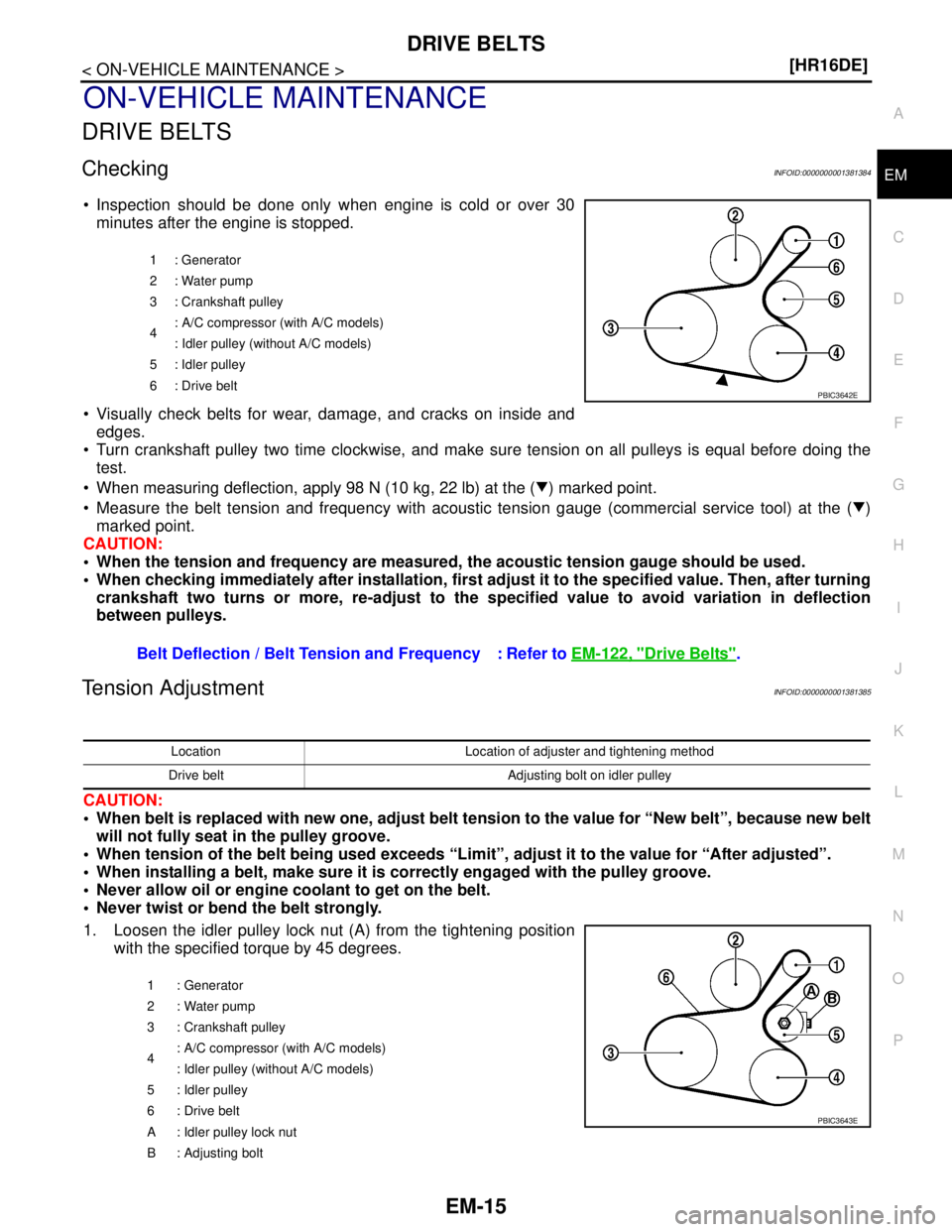
1. Loosen the idler pulley lock nut (A) from the tightening position
with the specified torque by 45 degrees.
1 : Generator
2 : Water pump
3 : Crankshaft pulley
4: A/C compressor (with A/C models)
: Idler pulley (without A/C models)
5 : Idler pulley
6: Drive belt
Belt Deflection / Belt Tension and Frequency : Refer to EM-122, "Drive Belts".
PBIC3642E
Location Location of adjuster and tightening method
Drive belt Adjusting bolt on idler pulley
1 : Generator
2: Water pump
3 : Crankshaft pulley
4: A/C compressor (with A/C models)
: Idler pulley (without A/C models)
5 : Idler pulley
6: Drive belt
A : Idler pulley lock nut
B : Adjusting bolt
PBIC3643E
Page 2718 of 5883
CAMSHAFT
EM-71
< ON-VEHICLE REPAIR >[HR16DE]
C
D
E
F
G
H
I
J
K
L
MA
EM
N
P O
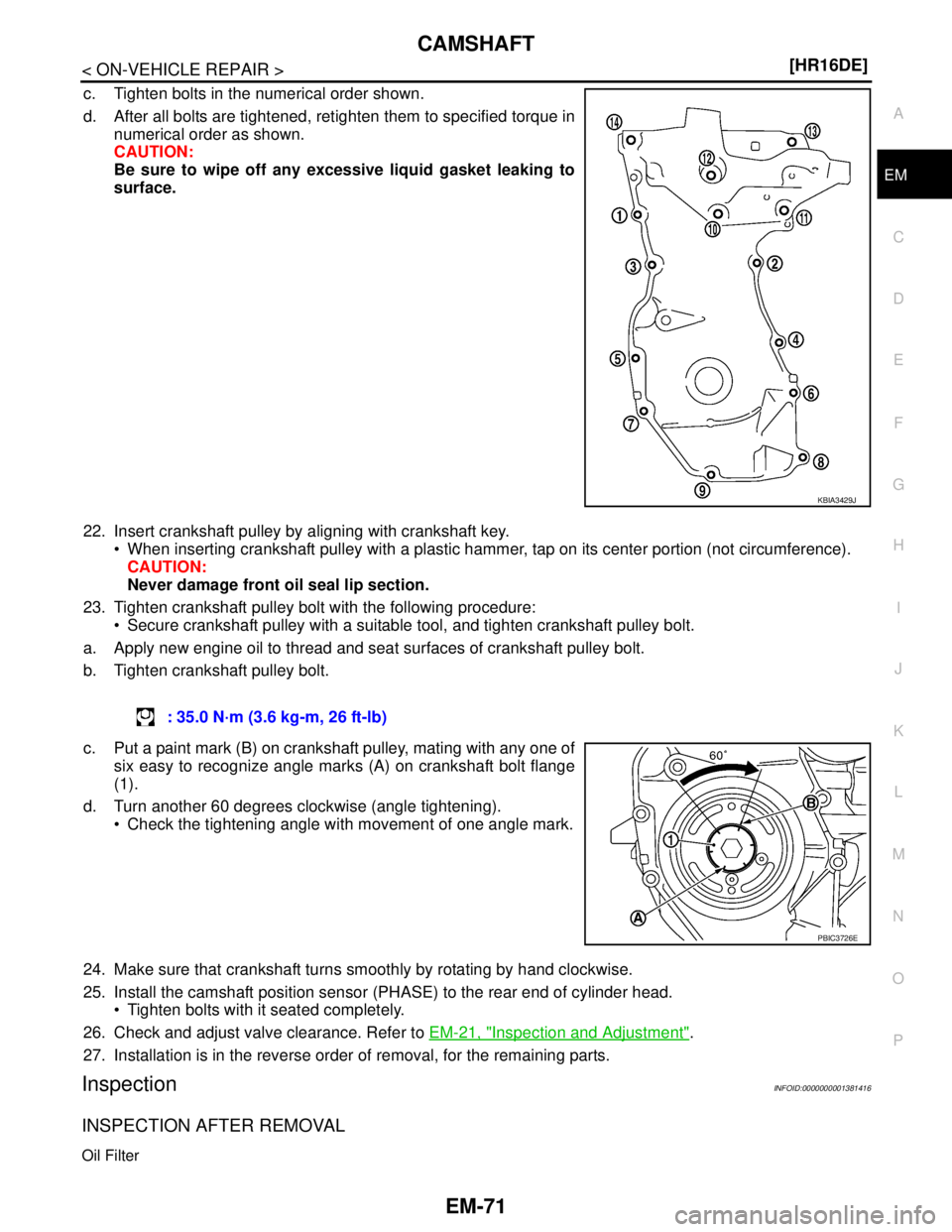
c. Tighten bolts in the numerical order shown.
d. After all bolts are tightened, retighten them to specified torque in
numerical order as shown.
CAUTION:
Be sure to wipe off any excessive liquid gasket leaking to
surface.
22. Insert crankshaft pulley by aligning with crankshaft key.
When inserting crankshaft pulley with a plastic hammer, tap on its center portion (not circumference).
CAUTION:
Never damage front oil seal lip section.
23. Tighten crankshaft pulley bolt with the following procedure:
Secure crankshaft pulley with a suitable tool, and tighten crankshaft pulley bolt.
a. Apply new engine oil to thread and seat surfaces of crankshaft pulley bolt.
b. Tighten crankshaft pulley bolt.
c. Put a paint mark (B) on crankshaft pulley, mating with any one of
six easy to recognize angle marks (A) on crankshaft bolt flange
(1).
d. Turn another 60 degrees clockwise (angle tightening).
Check the tightening angle with movement of one angle mark.
24. Make sure that crankshaft turns smoothly by rotating by hand clockwise.
25. Install the camshaft position sensor (PHASE) to the rear end of cylinder head.
Tighten bolts with it seated completely.
26. Check and adjust valve clearance. Refer to EM-21, "
Inspection and Adjustment".
27. Installation is in the reverse order of removal, for the remaining parts.
InspectionINFOID:0000000001381416
INSPECTION AFTER REMOVAL
Oil Filter
KBIA3429J
: 35.0 N·m (3.6 kg-m, 26 ft-lb)
PBIC3726E
Page 3004 of 5883
EXL-3
C
D
E
F
G
H
I
J
K
MA
B
EXL
N
O
P
TURN SIGNAL AND HAZARD WARNING
LAMPS ...............................................................
66
Wiring Diagram .......................................................66
PARKING, LICENSE PLATE AND TAIL
LAMPS ...............................................................
67
WITH DAYTIME LIGHT SYSTEM .............................67
WITH DAYTIME LIGHT SYSTEM : Wiring Dia-
gram ........................................................................
67
WITHOUT DAYTIME LIGHT SYSTEM ......................67
WITHOUT DAYTIME LIGHT SYSTEM : Wiring Di-
agram ......................................................................
68
STOP LAMP .......................................................69
Wiring Diagram .......................................................69
BACK-UP LAMP ................................................70
Wiring Diagram .......................................................70
ECU DIAGNOSIS .........................................71
BCM (BODY CONTROL MODULE) ...................71
Description ..............................................................71
IPDM E/R (INTELLIGENT POWER DISTRI-
BUTION MODULE ENGINE ROOM) .................
72
Description ..............................................................72
SYMPTOM DIAGNOSIS ..............................73
EXTERIOR LIGHTING SYSTEM SYMPTOMS ....73
Symptom Table .......................................................73
NORMAL OPERATING CONDITION .................75
Description ..............................................................75
BOTH SIDE HEADLAMPS DO NOT SWITCH
TO HIGH BEAM .................................................
76
Description ..............................................................76
Diagnosis Procedure ...............................................76
BOTH SIDE HEADLAMPS (LO) ARE NOT
TURNED ON .......................................................
77
Description ..............................................................77
Diagnosis Procedure ...............................................77
PARKING, LICENSE PLATE AND TAIL
LAMPS ARE NOT TURNED ON ........................
78
Description ..............................................................78
Diagnosis Procedure ...............................................78
BOTH SIDE FRONT FOG LAMPS ARE NOT
TURNED ON .......................................................
79
Description ..............................................................79
Diagnosis Procedure ...............................................79
PRECAUTION ..............................................80
PRECAUTIONS ..................................................80
Precaution for Supplemental Restraint System
(SRS) "AIR BAG" and "SEAT BELT PRE-TEN-
SIONER" .................................................................
80
ON-VEHICLE MAINTENANCE ....................81
HEADLAMP ......................................................81
Aiming Adjustment ...................................................81
FRONT FOG LAMP ..........................................83
Aiming Adjustment ...................................................83
ON-VEHICLE REPAIR .................................84
HEADLAMP ......................................................84
Bulb Replacement ...................................................84
Removal and Installation .........................................84
Disassembly and Assembly - Halogen ....................85
Disassembly and Assembly - Xenon .......................86
FRONT FOG LAMP ..........................................87
Bulb Replacement ...................................................87
Removal and Installation .........................................87
HEADLAMP AIMING CONTROL ......................88
Removal and Installation of Headlamp Aiming
Switch ......................................................................
88
Removal and Installation of Height Sensor .............89
AUTO LIGHT SYSTEM .....................................91
Removal and Installation of Light and Rain Sensor
....
91
SIDE TURN SIGNAL LAMP ..............................92
Bulb Replacement ...................................................92
Removal and Installation .........................................92
REAR COMBINATION LAMP ...........................93
Bulb Replacement ...................................................93
Removal and Installation .........................................93
Disassembly and Assembly .....................................93
HIGH-MOUNTED STOP LAMP ........................96
Bulb Replacement ...................................................96
Removal and Installation .........................................96
LICENSE PLATE LAMP ...................................98
Bulb Replacement ...................................................98
Removal and Installation .........................................98
REAR FOG LAMP ...........................................100
Bulb Replacement .................................................100
Removal and Installation .......................................100
LIGHTING & TURN SIGNAL SWITCH ...........101
Removal and Installation .......................................101
HAZARD SWITCH ..........................................102
Removal and Installation .......................................102
SERVICE DATA AND SPECIFICATIONS
(SDS) ..........................................................
103
Page 3111 of 5883
SQUEAK AND RATTLE TROUBLE DIAGNOSIS
EXT-7
< ON-VEHICLE MAINTENANCE >
C
D
E
F
G
H
I
J
L
MA
B
EXT
N
O
P
4. A loose license plate or bracket
Most of these incidents can be repaired by adjusting, securing or insulating the item(s) or component(s) caus-
ing the noise.
SUNROOF/HEADLINING
Noises in the sunroof/headlining area can often be traced to one of the following:
1. Sunroof lid, rail, linkage or seals making a rattle or light knocking noise
2. Sun visor shaft shaking in the holder
3. Front or rear windshield touching headliner and squeaking
Again, pressing on the components to stop the noise while duplicating the conditions can isolate most of these
incidents. Repairs usually consist of insulating with felt cloth tape.
OVERHEAD CONSOLE (FRONT AND REAR)
Overhead console noises are often caused by the console panel clips not being engaged correctly. Most of
these incidents are repaired by pushing up on the console at the clip locations until the clips engage.
In addition look for:
1. Loose harness or harness connectors.
2. Front console map/reading lamp lens loose.
3. Loose screws at console attachment points.
SEATS
When isolating seat noise it's important to note the position the seat is in and the load placed on the seat when
the noise is present. These conditions should be duplicated when verifying and isolating the cause of the
noise.
Cause of seat noise include:
1. Headrest rods and holder
2. A squeak between the seat pad cushion and frame
3. The rear seatback lock and bracket
These noises can be isolated by moving or pressing on the suspected components while duplicating the con-
ditions under which the noise occurs. Most of these incidents can be repaired by repositioning the component
or applying urethane tape to the contact area.
UNDERHOOD
Some interior noise may be caused by components under the hood or on the engine wall. The noise is then
transmitted into the passenger compartment.
Causes of transmitted underhood noise include:
1. Any component installed on the engine wall
2. Components that pass through the engine wall
3. Engine wall mounts and connectors
4. Loose radiator pins
5. Hood bumpers out of adjustment
6. Hood striker out of adjustment
These noises can be difficult to isolate since they cannot be reached from the interior of the vehicle. The best
method is to secure, move or insulate one component at a time and test drive the vehicle. Also, engine RPM
or load can be changed to isolate the noise. Repairs can usually be made by moving, adjusting, securing, or
insulating the component causing the noise.
Page 3264 of 5883
SQUEAK AND RATTLE TROUBLE DIAGNOSES
GW-5
< SYMPTOM DIAGNOSIS >
C
D
E
F
G
H
I
J
L
MA
B
GW
N
O
P
2. Trunk lid striker out of adjustment
3. The trunk lid torsion bars knocking together
4. A loose license plate or bracket
Most of these incidents can be repaired by adjusting, securing or insulating the item(s) or component(s) caus-
ing the noise.
SUNROOF/HEADLINING
Noises in the sunroof/headlining area can often be traced to one of the following:
1. Sunroof lid, rail, linkage or seals making a rattle or light knocking noise
2. Sun visor shaft shaking in the holder
3. Front or rear windshield touching headliner and squeaking
Again, pressing on the components to stop the noise while duplicating the conditions can isolate most of these
incidents. Repairs usually consist of insulating with felt cloth tape.
OVERHEAD CONSOLE (FRONT AND REAR)
Overhead console noises are often caused by the console panel clips not being engaged correctly. Most of
these incidents are repaired by pushing up on the console at the clip locations until the clips engage.
In addition look for:
1. Loose harness or harness connectors.
2. Front console map/reading lamp lense loose.
3. Loose screws at console attachment points.
SEATS
When isolating seat noise it's important to note the position the seat is in and the load placed on the seat when
the noise is present. These conditions should be duplicated when verifying and isolating the cause of the
noise.
Cause of seat noise include:
1. Headrest rods and holder
2. A squeak between the seat pad cushion and frame
3. The rear seatback lock and bracket
These noises can be isolated by moving or pressing on the suspected components while duplicating the con-
ditions under which the noise occurs. Most of these incidents can be repaired by repositioning the component
or applying urethane tape to the contact area.
UNDERHOOD
Some interior noise may be caused by components under the hood or on the engine wall. The noise is then
transmitted into the passenger compartment.
Causes of transmitted underhood noise include:
1. Any component mounted to the engine wall
2. Components that pass through the engine wall
3. Engine wall mounts and connectors
4. Loose radiator mounting pins
5. Hood bumpers out of adjustment
6. Hood striker out of adjustment
These noises can be difficult to isolate since they cannot be reached from the interior of the vehicle. The best
method is to secure, move or insulate one component at a time and test drive the vehicle. Also, engine RPM
or load can be changed to isolate the noise. Repairs can usually be made by moving, adjusting, securing, or
insulating the component causing the noise.
Page 3335 of 5883
HAC-2
PTC HEATER CONTROL SYSTEM ..................63
PTC HEATER (300 WATT) .......................................63
PTC HEATER (300 WATT) : Wiring Diagram -
PTC Heater (300 Watt) - .........................................
63
PTC HEATER (1500 WATT) .....................................67
PTC HEATER (1500 WATT) : Wiring Diagram -
PTC Heater (1500 Watt) - .......................................
68
SYMPTOM DIAGNOSIS .............................72
AIR CONDITIONER CONTROL ........................72
Symptom Matrix Chart ..........................................72
INSUFFICIENT COOLING .................................73
Component Function Check ...................................73
Performance Test Diagnoses .................................74
Performance Chart .................................................75
Test Reading ..........................................................76
Trouble Diagnoses for Unusual Pressure ...............77
INSUFFICIENT HEATING .................................81
Component Function Check ...................................81
NOISE ................................................................83
Component Function Check ...................................83
PRECAUTION .............................................84
PRECAUTIONS .................................................84
Precaution for Supplemental Restraint System
(SRS) "AIR BAG" and "SEAT BELT PRE-TEN-
SIONER" .................................................................
84
Precaution for Procedures Without Cowl Top Cov-
er ............................................................................
84
Working with HFC-134a (R-134a) ..........................84
Precaution for Service Equipment ..........................85
AUTO AIR CONDITIONER (W/O NAVI)
BASIC INSPECTION ...................................
86
DIAGNOSIS AND REPAIR WORKFLOW .........86
How to Perform Trouble Diagnosis For Quick And
Accurate Repair ......................................................
86
INSPECTION AND ADJUSTMENT ...................87
Operational Check ..................................................87
FUNCTION DIAGNOSIS .............................89
FUNCTION INFORMATION ..............................89
Component Part Location .......................................89
REFRIGERATION SYSTEM ..............................91
Refrigerant Cycle ....................................................91
Refrigerant System Protection ................................91
AUTOMATIC AIR CONDITIONER SYSTEM .....92
Control System Diagram ........................................92
Control System Description ....................................92
Discharge Air Flow .................................................94
Switches And Their Control Function ......................95
CAN COMMUNICATION SYSTEM ...................96
System Description .................................................96
DIAGNOSIS SYSTEM (BCM) ............................97
CONSULT-III Function (BCM) ................................97
SELF-DIAGNOSIS FUNCTION .........................98
Front Air Control Self-Diagnosis .............................98
A/C System Self-Diagnosis Code Chart ...............104
COMPONENT DIAGNOSIS ......................106
MODE DOOR MOTOR .....................................106
System Description ...............................................106
Mode Door Motor Component Function Check ....107
Mode Door Motor Diagnosis Procedure ................109
AIR MIX DOOR MOTOR ..................................110
System Description ...............................................110
Air Mix Door Motor Component Function Check ..111
Air Mix Door Motor Diagnosis Procedure ..............112
INTAKE DOOR MOTOR ...................................114
System Description ...............................................114
Intake Door Motor Component Function Check ....115
Intake Door Motor Diagnosis Procedure ...............116
BLOWER MOTOR CONTROL SYSTEM .........118
System Description ...............................................118
Front Blower Motor Component Function Check ..119
Front Blower Motor Diagnosis Procedure .............120
Front Blower Motor Component Inspection ..........123
MAGNET CLUTCH ...........................................124
System Description ...............................................124
Magnet Clutch Component Function Check .........124
Magnet Clutch Diagnosis Procedure ....................125
AMBIENT SENSOR ..........................................130
Component Description ........................................130
Ambient Sensor Diagnosis Procedure ..................130
Ambient Sensor Component Inspection ...............131
IN-VEHICLE SENSOR ......................................133
Component Description ........................................133
In-Vehicle Sensor Diagnosis Procedure ...............133
In-Vehicle Sensor Component Inspection .............135
SUNLOAD SENSOR ........................................136
System Description ...............................................136
Sunload Sensor Diagnosis Procedure ..................136
Sunload Component Inspection ............................137
INTAKE SENSOR .............................................139
Component Inspection ..........................................139
Intake Sensor Diagnosis Procedure .....................139
Intake Sensor Component Inspection ...................140
PTC HEATER CONTROL SYSTEM .................142