seat adjustment NISSAN TIIDA 2007 Service Owner's Guide
[x] Cancel search | Manufacturer: NISSAN, Model Year: 2007, Model line: TIIDA, Model: NISSAN TIIDA 2007Pages: 5883, PDF Size: 78.95 MB
Page 4604 of 5883

SE-8
< SYMPTOM DIAGNOSIS >
SQUEAK AND RATTLE TROUBLE DIAGNOSES
2. Trunk lid striker out of adjustment
3. The trunk lid torsion bars knocking together
4. A loose license plate or bracket
Most of these incidents can be repaired by adjusting, securing or insulating the item(s) or component(s) caus-
ing the noise.
SUNROOF/HEADLINING
Noises in the sunroof/headlining area can often be traced to one of the following:
1. Sunroof lid, rail, linkage or seals making a rattle or light knocking noise
2. Sun visor shaft shaking in the holder
3. Front or rear windshield touching headliner and squeaking
Again, pressing on the components to stop the noise while duplicating the conditions can isolate most of these
incidents. Repairs usually consist of insulating with felt cloth tape.
OVERHEAD CONSOLE (FRONT AND REAR)
Overhead console noises are often caused by the console panel clips not being engaged correctly. Most of
these incidents are repaired by pushing up on the console at the clip locations until the clips engage.
In addition look for:
1. Loose harness or harness connectors.
2. Front console map/reading lamp lense loose.
3. Loose screws at console attachment points.
SEATS
When isolating seat noise it's important to note the position the seat is in and the load placed on the seat when
the noise is present. These conditions should be duplicated when verifying and isolating the cause of the
noise.
Cause of seat noise include:
1. Headrest rods and holder
2. A squeak between the seat pad cushion and frame
3. The rear seatback lock and bracket
These noises can be isolated by moving or pressing on the suspected components while duplicating the con-
ditions under which the noise occurs. Most of these incidents can be repaired by repositioning the component
or applying urethane tape to the contact area.
UNDERHOOD
Some interior noise may be caused by components under the hood or on the engine wall. The noise is then
transmitted into the passenger compartment.
Causes of transmitted underhood noise include:
1. Any component mounted to the engine wall
2. Components that pass through the engine wall
3. Engine wall mounts and connectors
4. Loose radiator mounting pins
5. Hood bumpers out of adjustment
6. Hood striker out of adjustment
These noises can be difficult to isolate since they cannot be reached from the interior of the vehicle. The best
method is to secure, move or insulate one component at a time and test drive the vehicle. Also, engine RPM
or load can be changed to isolate the noise. Repairs can usually be made by moving, adjusting, securing, or
insulating the component causing the noise.
Page 4861 of 5883
ST-6
< ON-VEHICLE MAINTENANCE >
STEERING WHEEL
ON-VEHICLE MAINTENANCE
STEERING WHEEL
On-Vehicle Inspection and ServiceINFOID:0000000001282496
CHECKING CONDITION OF INSTALLATION
Check installation conditions of steering gear assembly, front suspension assembly, axle and steering col-
umn assembly.
Check if movement exists when steering wheel is moved up and down, to the left and right and to the axial
direction.
Check steering gear assembly mounting bolts and nuts for looseness. Refer to ST-12, "
Removal and Instal-
lation" .
CHECKING STEERING WHEEL PLAY
Turn steering wheel so that front wheels come to the straight-ahead position. Start engine and lightly turn
steering wheel to the left and right until front wheels start to move. Measure steering wheel movement on the
outer circumference.
When the measurement value is outside the standard value, check backlash for each joint of steering col-
umn assembly and installation condition of steering gear assembly.
CHECKING NEUTRAL POSITION STEERING WHEEL
Make sure that steering gear assembly, steering column assembly and steering wheel are installed in the
correct position.
Perform neutral position inspection after wheel alignment. Refer to SR-2, "
Precaution for Supplemental
Restraint System (SRS) "AIR BAG" and "SEAT BELT PRE-TENSIONER"" .
Set vehicle to the straight-ahead position and confirm steering wheel is in the neutral position.
Loosen outer socket lock nut and turn inner socket to left and right equally to make fine adjustments if steer-
ing wheel is not in the neutral position.
CHECKING STEERING WHEEL TURNING FORCE
1. Park vehicle on a level and dry surface, set parking brake.
2. Start engine.
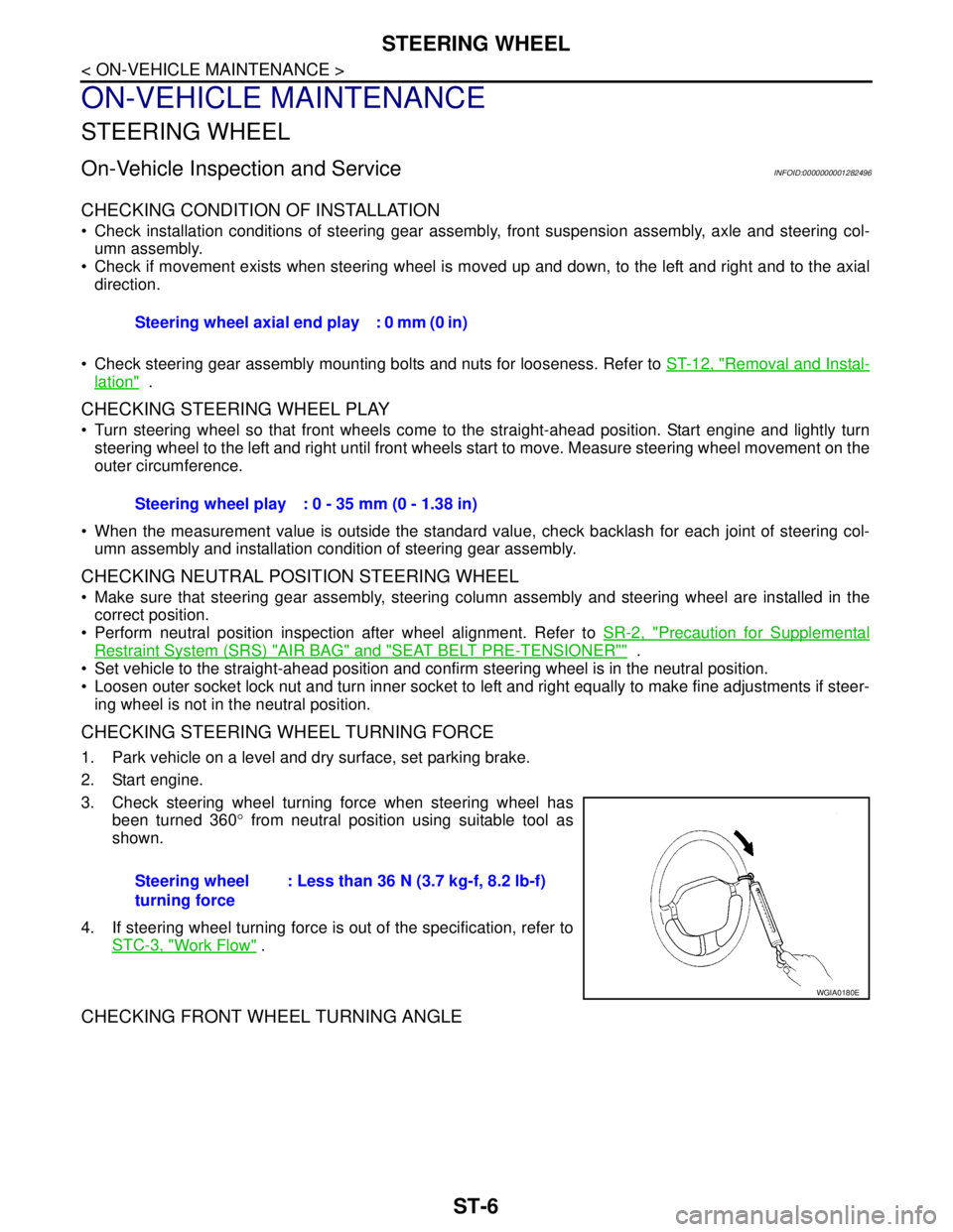
3. Check steering wheel turning force when steering wheel has
been turned 360° from neutral position using suitable tool as
shown.
4. If steering wheel turning force is out of the specification, refer to
STC-3, "
Work Flow" .
CHECKING FRONT WHEEL TURNING ANGLE
Steering wheel axial end play : 0 mm (0 in)
Steering wheel play : 0 - 35 mm (0 - 1.38 in)
Steering wheel
turning force: Less than 36 N (3.7 kg-f, 8.2 lb-f)
WGIA0180E
Page 4953 of 5883
TM-7
C
E
F
G
H
I
J
K
L
MA
B
TM
N
O
P Precaution for Supplemental Restraint System
(SRS) "AIR BAG" and "SEAT BELT PRE-TEN-
SIONER" ...............................................................
465
Precaution Necessary for Steering Wheel Rota-
tion After Battery Disconnect .................................
465
Precaution for On Board Diagnosis (OBD) System
of A/T and Engine (For Type1 Only) .....................
465
Precaution .............................................................466
Service Notice or Precaution .................................467
Wiring Diagram and Trouble Diagnosis ................467
PREPARATION .........................................468
PREPARATION ................................................468
Special Service Tool .............................................468
Commercial Service Tool ......................................471
ON-VEHICLE MAINTENANCE ..................473
A/T FLUID .........................................................473
Checking A/T Fluid ................................................473
Changing A/T Fluid ...............................................473
A/T Fluid Cooler Cleaning .....................................474
STALL TEST ....................................................477
Inspection and Judgment ......................................477
LINE PRESSURE TEST ...................................480
Inspection and Judgment ......................................480
ROAD TEST .....................................................482
Description ............................................................482
Check Before Engine Is Started ............................482
Check at Idle .........................................................483
Cruise Test - Part 1 ...............................................485
Cruise Test - Part 2 ...............................................487
Cruise Test - Part 3 ...............................................488
Vehicle Speed When Shifting Gears .....................490
Vehicle Speed When Performing and Releasing
Complete Lock-up .................................................
490
ON-VEHICLE REPAIR ...............................491
TRANSMISSION CONTROL MODULE ...........491
Exploded View ......................................................491
Removal and Installation .......................................491
SHIFT CONTROL SYSTEM .............................493
Control Device Removal and Installation ..............493
Control Device Disassembly and Assembly ..........496
Selector Lever Knob Removal and Installation .....496
Adjustment of A/T Position ....................................497
Checking of A/T Position .......................................497
KEY INTERLOCK CABLE ...............................499
Removal and Installation .......................................499
AIR BREATHER HOSE ....................................502
Removal and Installation .......................................502
REMOVAL AND INSTALLATION .............503
TRANSAXLE ASSEMBLY ..............................503
Exploded View .......................................................503
Removal and Installation .......................................503
DISASSEMBLY AND ASSEMBLY ............506
OVERHAUL .....................................................506
Component ............................................................506
Oil Channel ............................................................512
Location of Adjusting Shims, Needle Bearings and
Thrust Washers .....................................................
513
Location of Snap Rings .........................................514
DISASSEMBLY ...............................................515
Disassembly ..........................................................515
REPAIR FOR COMPONENT PARTS .............530
Manual Shaft .........................................................530
Oil Pump ................................................................533
Control Valve Assembly ........................................536
Control Valve Upper Body .....................................545
Control Valve Lower Body .....................................548
Reverse Clutch ......................................................551
High Clutch ............................................................555
Forward and Overrun Clutches .............................560
Low & Reverse Brake ............................................566
Rear Internal Gear and Forward Clutch Hub .........571
Output Shaft, Output Gear, Idler Gear, Reduction
Pinion Gear and Bearing Retainer .........................
574
Band Servo Piston Assembly ................................580
Final Drive .............................................................585
ASSEMBLY .....................................................590
Assembly (1) ..........................................................590
Adjustment (1) .......................................................591
Assembly (2) ..........................................................596
Adjustment (2) .......................................................600
Assembly (3) ..........................................................604
SERVICE DATA AND SPECIFICATIONS
(SDS) ..........................................................
612
SERVICE DATA AND SPECIFICATIONS
(SDS) ...............................................................
612
General Specification ............................................612
Vehicle Speed at Which Gear Shifting Occurs ......612
Vehicle Speed at When Lock-up Occurs/Releases
..
612
Stall Speed ............................................................612
Line Pressure ........................................................612
Adjusting shims, Needle Bearings, Thrust Wash-
ers and Snap Rings ...............................................
613
Control Valves .......................................................614
Accumulator ...........................................................614
Clutches and Brakes .............................................614
Final Drive .............................................................616
Planetary Carrier ...................................................616
Oil Pump ................................................................616
Input Shaft .............................................................616
Reduction Pinion Gear ..........................................616
Page 5804 of 5883
WW-2
Wiring Diagram .......................................................36
REAR WIPER AND WASHER SYSTEM ...........41
Wiring Diagram .......................................................41
HEADLAMP WASHER SYSTEM ......................47
Wiring Diagram .......................................................47
ECU DIAGNOSIS ........................................51
BCM (BODY CONTROL MODULE) ..................51
Reference Value .....................................................51
IPDM E/R (INTELLIGENT POWER DISTRI-
BUTION MODULE ENGINE ROOM) .................
52
Reference Value .....................................................52
Fail Safe .................................................................52
SYMPTOM DIAGNOSIS .............................54
WIPER AND WASHER SYSTEM SYMPTOMS
...
54
Symptom Table ......................................................54
NORMAL OPERATING CONDITION ................57
Description ..............................................................57
FRONT WIPER DOES NOT OPERATE ............58
Description ..............................................................58
Diagnosis Procedure ..............................................58
HEADLAMP WASHER DOES NOT OPER-
ATE ....................................................................
60
Description ..............................................................60
Diagnosis Procedure ..............................................60
PRECAUTION .............................................61
PRECAUTIONS .................................................61
Precaution for Supplemental Restraint System
(SRS) "AIR BAG" and "SEAT BELT PRE-TEN-
SIONER" .................................................................
61
Precaution for Procedure without Cowl Top Cover ...61
ON-VEHICLE REPAIR ................................62
HEADLAMP WASHER NOZZLE AND TUBE ...62
Exploded View ........................................................62
Removal and Installation .........................................62
Inspection ................................................................63
WASHER TANK ................................................64
Removal and Installation .........................................64
WASHER PUMP ................................................65
Removal and Installation .........................................65
HEADLAMP WASHER PUMP ..........................66
Removal and Installation .........................................66
FRONT WASHER NOZZLE AND TUBE ...........67
Washer Tube Layout ...............................................67
Removal and Installation .........................................67
Inspection ................................................................67
Adjustment ..............................................................68
FRONT WIPER ARM .........................................69
Exploded View ........................................................69
Removal and Installation .........................................70
Adjustment ..............................................................71
FRONT WIPER DRIVE ASSEMBLY .................72
Exploded View ........................................................72
Removal and Installation .........................................73
Adjustment ..............................................................73
RAIN SENSOR ..................................................75
Exploded View ........................................................75
Removal and Installation .........................................75
WIPER AND WASHER SWITCH ......................76
Exploded View ........................................................76
Removal and Installation .........................................76
REAR WIPER MOTOR ......................................77
Exploded View ........................................................77
Removal and Installation .........................................77
Adjustment ..............................................................78
REAR WASHER NOZZLE AND TUBE .............80
Washer Tube Layout ...............................................80
Removal and Installation .........................................80
Adjustment ..............................................................81