brake fluid NISSAN TIIDA 2007 Service Owner's Manual
[x] Cancel search | Manufacturer: NISSAN, Model Year: 2007, Model line: TIIDA, Model: NISSAN TIIDA 2007Pages: 5883, PDF Size: 78.95 MB
Page 229 of 5883
REAR DISC BRAKE
BR-37
< DISASSEMBLY AND ASSEMBLY >
C
D
E
G
H
I
J
K
L
MA
B
BR
N
O
P
REAR DISC BRAKE
Disassembly and AssemblyINFOID:0000000001724669
DISASSEMBLY
1. Remove the sliding pin bolt, and then remove the pad, shim, shim cover, and pad retainer from the torque
member and cylinder.
2. Remove sliding pin boot from torque member.
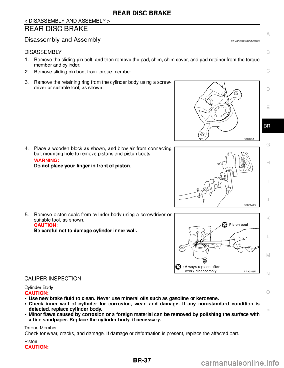
3. Remove the retaining ring from the cylinder body using a screw-
driver or suitable tool, as shown.
4. Place a wooden block as shown, and blow air from connecting
bolt mounting hole to remove pistons and piston boots.
WARNING:
Do not place your finger in front of piston.
5. Remove piston seals from cylinder body using a screwdriver or
suitable tool, as shown.
CAUTION:
Be careful not to damage cylinder inner wall.
CALIPER INSPECTION
Cylinder Body
CAUTION:
Use new brake fluid to clean. Never use mineral oils such as gasoline or kerosene.
Check inner wall of cylinder for corrosion, wear, and damage. If any non-standard condition is
detected, replace cylinder body.
Minor flaws caused by corrosion or a foreign material can be removed by polishing the surface with
a fine sandpaper. Replace the cylinder body, if necessary.
Torque Member
Check for wear, cracks, and damage. If damage or deformation is present, replace the affected part.
Piston
CAUTION:
SBR028A
BRD0041D
PFIA0269E
Page 230 of 5883
BR-38
< DISASSEMBLY AND ASSEMBLY >
REAR DISC BRAKE
Since the piston surface is plated, do not repair using sandpaper.
Check piston surface for corrosion, wear, and damage. If any non-standard condition is detected, replace
applicable part.
Sliding Pin Bolts and Sliding Pin Boots
Check that there is no wear, damage, or cracks in the sliding pin bolts and sliding pin boots, and if there are,
replace them.
ASSEMBLY
CAUTION:
Do not use Nissan Rubber Grease (KRE00 00010 or KRE00 00010 01) when assembling.
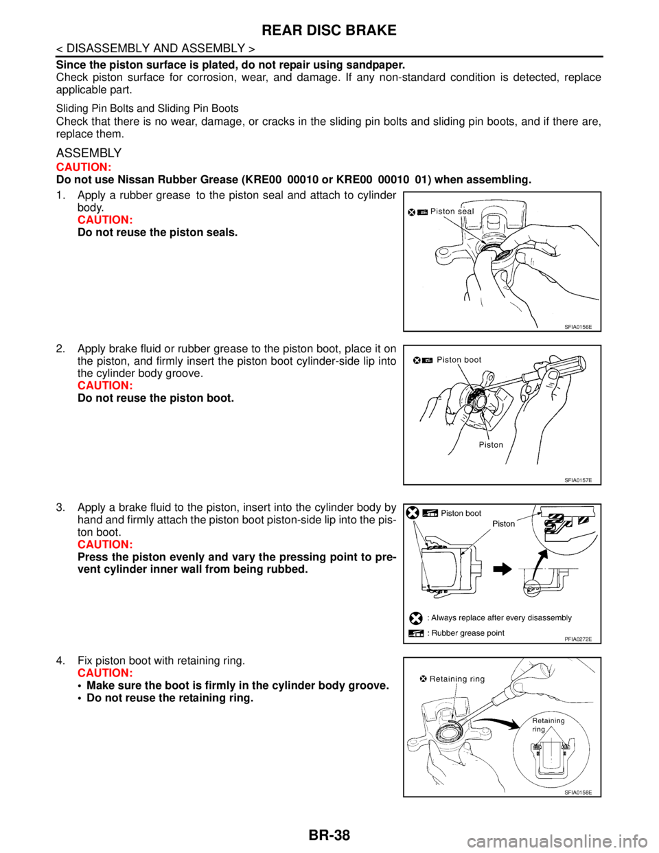
1. Apply a rubber grease to the piston seal and attach to cylinder
body.
CAUTION:
Do not reuse the piston seals.
2. Apply brake fluid or rubber grease to the piston boot, place it on
the piston, and firmly insert the piston boot cylinder-side lip into
the cylinder body groove.
CAUTION:
Do not reuse the piston boot.
3. Apply a brake fluid to the piston, insert into the cylinder body by
hand and firmly attach the piston boot piston-side lip into the pis-
ton boot.
CAUTION:
Press the piston evenly and vary the pressing point to pre-
vent cylinder inner wall from being rubbed.
4. Fix piston boot with retaining ring.
CAUTION:
Make sure the boot is firmly in the cylinder body groove.
Do not reuse the retaining ring.
SFIA0156E
SFIA0157E
PFIA0272E
SFIA0158E
Page 232 of 5883
BR-40
< SERVICE DATA AND SPECIFICATIONS (SDS)
SERVICE DATA AND SPECIFICATIONS (SDS)
SERVICE DATA AND SPECIFICATIONS (SDS)
SERVICE DATA AND SPECIFICATIONS (SDS)
General SpecificationINFOID:0000000001716911
Brake PedalINFOID:0000000001716912
Unit: mm (in)
Check ValveINFOID:0000000001716913
Brake BoosterINFOID:0000000001716914
Vacuum type
Front Disc BrakeINFOID:0000000001716915
Unit: mm (in)
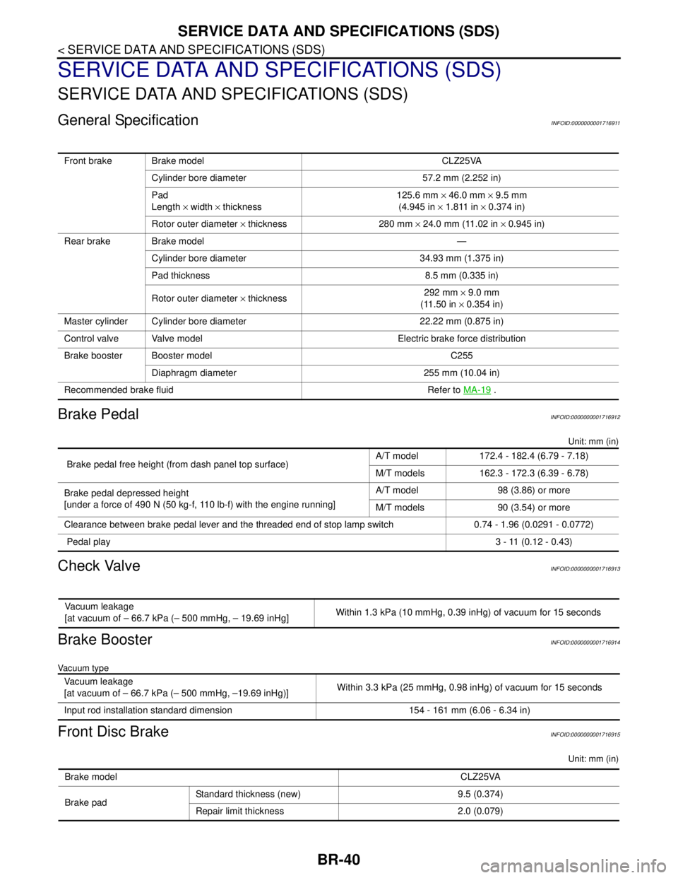
Front brake Brake model CLZ25VA
Cylinder bore diameter 57.2 mm (2.252 in)
Pad
Length × width × thickness125.6 mm × 46.0 mm × 9.5 mm
(4.945 in × 1.811 in × 0.374 in)
Rotor outer diameter × thickness 280 mm × 24.0 mm (11.02 in × 0.945 in)
Rear brake Brake model —
Cylinder bore diameter 34.93 mm (1.375 in)
Pad thickness 8.5 mm (0.335 in)
Rotor outer diameter × thickness292 mm × 9.0 mm
(11.50 in × 0.354 in)
Master cylinder Cylinder bore diameter 22.22 mm (0.875 in)
Control valve Valve model Electric brake force distribution
Brake booster Booster model C255
Diaphragm diameter 255 mm (10.04 in)
Recommended brake fluid Refer to MA-19
.
Brake pedal free height (from dash panel top surface)A/T model 172.4 - 182.4 (6.79 - 7.18)
M/T models 162.3 - 172.3 (6.39 - 6.78)
Brake pedal depressed height
[under a force of 490 N (50 kg-f, 110 lb-f) with the engine running]A/T model 98 (3.86) or more
M/T models 90 (3.54) or more
Clearance between brake pedal lever and the threaded end of stop lamp switch 0.74 - 1.96 (0.0291 - 0.0772)
Pedal play3 - 11 (0.12 - 0.43)
Vacuum leakage
[at vacuum of – 66.7 kPa (– 500 mmHg, – 19.69 inHg]Within 1.3 kPa (10 mmHg, 0.39 inHg) of vacuum for 15 seconds
Vacuum leakage
[at vacuum of – 66.7 kPa (– 500 mmHg, –19.69 inHg)]Within 3.3 kPa (25 mmHg, 0.98 inHg) of vacuum for 15 seconds
Input rod installation standard dimension 154 - 161 mm (6.06 - 6.34 in)
Brake modelCLZ25VA
Brake padStandard thickness (new) 9.5 (0.374)
Repair limit thickness 2.0 (0.079)
Page 235 of 5883

BRC-2
C1110, C1170 ABS ACTUATOR AND ELEC-
TRIC UNIT (CONTROL UNIT) ...........................
38
DTC Logic ...............................................................38
Diagnosis Procedure ..............................................38
Special Repair Requirement ...................................38
C1111 ABS MOTOR, MOTOR RELAY SYS-
TEM ....................................................................
39
Description ..............................................................39
DTC Logic ...............................................................39
Diagnosis Procedure ..............................................39
Component Inspection ............................................40
Special Repair Requirement ...................................40
C1115 WHEEL SENSOR ...................................41
Description ..............................................................41
DTC Logic ...............................................................41
Diagnosis Procedure ..............................................41
Component Inspection ............................................42
Special Repair Requirement ...................................43
C1116 STOP LAMP SWITCH ............................44
Description ..............................................................44
DTC Logic ...............................................................44
Diagnosis Procedure ..............................................44
Special Repair Requirement ...................................45
C1120, C1122, C1124, C1126 IN ABS SOL .....46
Description ..............................................................46
DTC Logic ...............................................................46
Diagnosis Procedure ..............................................46
Component Inspection ............................................47
Special Repair Requirement ...................................48
C1121, C1123, C1125, C1127 OUT ABS SOL ...49
Description ..............................................................49
DTC Logic ...............................................................49
Diagnosis Procedure ..............................................49
Component Inspection ............................................50
Special Repair Requirement ...................................51
C1130, C1131, C1132, C1133, C1136 EN-
GINE SIGNAL ....................................................
52
Description ..............................................................52
DTC Logic ...............................................................52
Diagnosis Procedure ..............................................52
Special Repair Requirement ...................................52
C1140 ACTUATOR RLY ...................................54
Description ..............................................................54
DTC Logic ...............................................................54
Diagnosis Procedure ..............................................54
Component Inspection ............................................55
Special Repair Requirement ...................................55
C1155 BRAKE FLUID LEVEL SWITCH ............56
Description ..............................................................56
DTC Logic ...............................................................56
Diagnosis Procedure ..............................................56
Component Inspection ............................................57
Special Repair Requirement ...................................57
U1000 CAN COMM CIRCUIT ............................59
Description ..............................................................59
DTC Logic ...............................................................59
Diagnosis Procedure ...............................................59
Special Repair Requirement ...................................59
ABS WARNING LAMP ......................................60
Description ..............................................................60
Component Function Check ...................................60
Diagnosis Procedure ...............................................60
BRAKE WARNING LAMP .................................61
Description ..............................................................61
Component Function Check ...................................61
Diagnosis Procedure ...............................................61
ECU DIAGNOSIS .......................................62
ABS ACTUATOR AND ELECTRIC UNIT
(CONTROL UNIT) ..............................................
62
Reference Value .....................................................62
Wiring Diagram - LHD .............................................67
Wiring Diagram - RHD ............................................69
Fail-Safe ..................................................................70
DTC No. Index ........................................................71
SYMPTOM DIAGNOSIS ............................73
ABS ....................................................................73
Symptom Table .......................................................73
EXCESSIVE ABS FUNCTION OPERATION
FREQUENCY .....................................................
74
Diagnosis Procedure ...............................................74
UNEXPECTED PEDAL REACTION ..................75
Diagnosis Procedure ...............................................75
THE BRAKING DISTANCE IS LONG ...............76
Diagnosis Procedure ...............................................76
ABS FUNCTION DOES NOT OPERATE ..........77
Diagnosis Procedure ...............................................77
PEDAL VIBRATION OR ABS OPERATION
SOUND OCCURS ..............................................
78
Diagnosis Procedure ...............................................78
NORMAL OPERATING CONDITION ................79
Description ..............................................................79
PRECAUTION ............................................80
PRECAUTIONS .................................................80
Precaution for Supplemental Restraint System
(SRS) "AIR BAG" and "SEAT BELT PRE-TEN-
SIONER" .................................................................
80
Precaution for Brake System ..................................80
Precaution for Brake Control ...................................80
Precaution for Harness Repair ................................81
Page 237 of 5883

BRC-4
C1115 WHEEL SENSOR .................................124
Description .............................................................124
DTC Logic ..............................................................124
Diagnosis Procedure .............................................124
Component Inspection ...........................................125
Special Repair Requirement ..................................126
C1116 STOP LAMP SWITCH ..........................127
Description .............................................................127
DTC Logic ..............................................................127
Diagnosis Procedure .............................................127
Special Repair Requirement ..................................128
C1120, C1122, C1124, C1126 IN ABS SOL ...129
Description .............................................................129
DTC Logic ..............................................................129
Diagnosis Procedure .............................................129
Component Inspection ...........................................130
Special Repair Requirement ..................................131
C1121, C1123, C1125, C1127 OUT ABS SOL .132
Description .............................................................132
DTC Logic ..............................................................132
Diagnosis Procedure .............................................132
Component Inspection ...........................................133
Special Repair Requirement ..................................134
C1130, C1131, C1132, C1133, C1136 EN-
GINE SIGNAL ..................................................
135
Description .............................................................135
DTC Logic ..............................................................135
Diagnosis Procedure .............................................135
Special Repair Requirement ..................................135
C1140 ACTUATOR RLY .................................137
Description .............................................................137
DTC Logic ..............................................................137
Diagnosis Procedure .............................................137
Component Inspection ...........................................138
Special Repair Requirement ..................................138
C1142 PRESS SENSOR .................................139
Description .............................................................139
DTC Logic ..............................................................139
Diagnosis Procedure .............................................139
Component Inspection ...........................................141
Special Repair Requirement ..................................141
C1143, C1144 STEERING ANGLE SENSOR .142
Description .............................................................142
DTC Logic ..............................................................142
Diagnosis Procedure .............................................142
Component Inspection ...........................................143
Special Repair Requirement ..................................143
C1155 BRAKE FLUID LEVEL SWITCH ..........145
Description .............................................................145
DTC Logic ..............................................................145
Diagnosis Procedure .............................................145
Component Inspection ...........................................146
Special Repair Requirement ..................................146
C1156 ST ANG SEN COM CIR ........................148
Description ............................................................148
DTC Logic .............................................................148
Diagnosis Procedure .............................................148
C1160 DECEL G SEN SET ..............................149
Description ............................................................149
DTC Logic .............................................................149
Diagnosis Procedure .............................................149
C1163 ST ANGLE SEN SAFE .........................150
Description ............................................................150
DTC Logic .............................................................150
Diagnosis Procedure .............................................150
C1179 ABS DELTA S SEN NG ........................151
Description ............................................................151
DTC Logic .............................................................151
Diagnosis Procedure .............................................151
Component Inspection ..........................................152
Special Repair Requirement .................................152
U1000 CAN COMM CIRCUIT ...........................153
Description ............................................................153
DTC Logic .............................................................153
Diagnosis Procedure .............................................153
Special Repair Requirement .................................153
VDC OFF SWITCH ...........................................154
Description ............................................................154
Component Function Check .................................154
Diagnosis Procedure .............................................154
Component Inspection ..........................................155
ABS WARNING LAMP .....................................156
Description ............................................................156
Component Function Check .................................156
Diagnosis Procedure .............................................156
BRAKE WARNING LAMP ................................157
Description ............................................................157
Component Function Check .................................157
Diagnosis Procedure .............................................157
VDC OFF INDICATOR LAMP ..........................158
Description ............................................................158
Component Function Check .................................158
Diagnosis Procedure .............................................158
SLIP INDICATOR LAMP ..................................159
Description ............................................................159
Component Function Check .................................159
Diagnosis Procedure .............................................159
ECU DIAGNOSIS ......................................160
ABS ACTUATOR AND ELECTRIC UNIT
(CONTROL UNIT) .............................................
160
Reference Value ...................................................160
Wiring Diagram - LHD ...........................................165
Wiring Diagram - RHD ..........................................167
Page 248 of 5883
![NISSAN TIIDA 2007 Service Owners Manual VDC
BRC-15
< FUNCTION DIAGNOSIS >[ABS]
C
D
E
G
H
I
J
K
L
MA
B
BRC
N
O
P
Component DescriptionINFOID:0000000001731211
1. Front wheel sensor
LH E18
RH E1172. ABS actuator and electric unit (con-
trol un](/img/5/57395/w960_57395-247.png "NISSAN TIIDA 2007 Service Owners Manual VDC
BRC-15
< FUNCTION DIAGNOSIS >[ABS]
C
D
E
G
H
I
J
K
L
MA
B
BRC
N
O
P
Component DescriptionINFOID:0000000001731211
1. Front wheel sensor
LH E18
RH E1172. ABS actuator and electric unit (con-
trol un")
VDC
BRC-15
< FUNCTION DIAGNOSIS >[ABS]
C
D
E
G
H
I
J
K
L
MA
B
BRC
N
O
P
Component DescriptionINFOID:0000000001731211
1. Front wheel sensor
LH E18
RH E1172. ABS actuator and electric unit (con-
trol unit) E1253. Combination meter M24
4. Rear wheel sensor
LH C11
RH C105. Yaw rate/side/decel G sensor M108 6. Steering angle sensor M17 (view
with steering wheel removed)
7. VDC OFF switch M257 8. Active booster E49 9. Delta stroke sensor E114
10. Brake fluid level switch E21 11. Front pressure sensor E31 12. Rear pressure sensor E32
Component parts Reference
ABS actuator and electric unit (control unit)Pump
BRC-39, "
Description"Motor
Actuator relayBRC-54, "
Description"
Solenoid valveBRC-46, "Description"
VDC switch-over valve
(CV1, CV2, SV1, SV2)XX-XX, "*****"
Wheel sensorBRC-30, "Description"
Yaw rate/side/decel G sensorXX-XX, "*****"
Steering angle sensorXX-XX, "*****"
VDC OFF switchXX-XX, "*****"
ABS warning lampBRC-60, "Description"
Brake warning lampBRC-61, "Description"
VDC OFF indicator lampXX-XX, "*****"
SLIP indicator lampXX-XX, "*****"
Front pressure sensor
XX-XX, "*****"
Rear pressure sensor
Active boosterXX-XX, "*****"
Delta stroke sensorXX-XX, "*****"
Page 249 of 5883
![NISSAN TIIDA 2007 Service Owners Manual BRC-16
< FUNCTION DIAGNOSIS >[ABS]
TCS
TCS
System DiagramINFOID:0000000001731212
System DescriptionINFOID:0000000001731213
Traction Control System is a function that electronically controls engine t](/img/5/57395/w960_57395-248.png "NISSAN TIIDA 2007 Service Owners Manual BRC-16
< FUNCTION DIAGNOSIS >[ABS]
TCS
TCS
System DiagramINFOID:0000000001731212
System DescriptionINFOID:0000000001731213
Traction Control System is a function that electronically controls engine t")
BRC-16
< FUNCTION DIAGNOSIS >[ABS]
TCS
TCS
System DiagramINFOID:0000000001731212
System DescriptionINFOID:0000000001731213
Traction Control System is a function that electronically controls engine torque, brake fluid pressure and A/T
gear position to ensure the optimum slippage ratio at drive wheels by computing wheel speed signals from 4
wheel sensors. When ABS actuator and electric unit (control unit) detects a spin at drive wheels (rear
wheels), it compares wheel speed signals from all 4 wheels. At this time, LH and RH rear brake fluid pres-
sure are controlled, while fuel being cut to engine and throttle valve being closed to reduce engine torque by
the control unit. Further more, throttle position is continuously controlled to ensure the optimum engine
torque at all times.
During TCS operation, it informs driver of system operation by flashing SLIP indicator lamp.
Electrical system diagnosis by CONSULT-III is available.
AWFIA0012GB
Page 251 of 5883
![NISSAN TIIDA 2007 Service Owners Manual BRC-18
< FUNCTION DIAGNOSIS >[ABS]
TCS
Component Description
INFOID:0000000001731215
1. Front wheel sensor
LH E18
RH E1172. ABS actuator and electric unit (con-
trol unit) E1253. Combination meter M24](/img/5/57395/w960_57395-250.png "NISSAN TIIDA 2007 Service Owners Manual BRC-18
< FUNCTION DIAGNOSIS >[ABS]
TCS
Component Description
INFOID:0000000001731215
1. Front wheel sensor
LH E18
RH E1172. ABS actuator and electric unit (con-
trol unit) E1253. Combination meter M24")
BRC-18
< FUNCTION DIAGNOSIS >[ABS]
TCS
Component Description
INFOID:0000000001731215
1. Front wheel sensor
LH E18
RH E1172. ABS actuator and electric unit (con-
trol unit) E1253. Combination meter M24
4. Rear wheel sensor
LH C11
RH C105. Yaw rate/side/decel G sensor M108 6. Steering angle sensor M17 (view
with steering wheel removed)
7. VDC OFF switch M257 8. Active booster E49 9. Delta stroke sensor E114
10. Brake fluid level switch E21 11. Front pressure sensor E31 12. Rear pressure sensor E32
Component parts Reference
ABS actuator and electric unit (control unit)Pump
BRC-39, "
Description"Motor
Actuator relayBRC-54, "
Description"
Solenoid valveBRC-46, "Description"
VDC switch-over valve
(CV1, CV2, SV1, SV2)XX-XX, "*****"
Wheel sensorBRC-30, "Description"
Yaw rate/side/decel G sensorXX-XX, "*****"
Steering angle sensorXX-XX, "*****"
VDC OFF switchXX-XX, "*****"
ABS warning lampBRC-60, "Description"
Brake warning lampBRC-61, "Description"
VDC OFF indicator lampXX-XX, "*****"
SLIP indicator lampXX-XX, "*****"
Front pressure sensor
XX-XX, "*****"
Rear pressure sensor
Active boosterXX-XX, "*****"
Delta stroke sensorXX-XX, "*****"
Page 254 of 5883
![NISSAN TIIDA 2007 Service Owners Manual ABS
BRC-21
< FUNCTION DIAGNOSIS >[ABS]
C
D
E
G
H
I
J
K
L
MA
B
BRC
N
O
P
Component DescriptionINFOID:0000000001731219
1. Front wheel sensor
LH E18
RH E1172. ABS actuator and electric unit (con-
trol un](/img/5/57395/w960_57395-253.png "NISSAN TIIDA 2007 Service Owners Manual ABS
BRC-21
< FUNCTION DIAGNOSIS >[ABS]
C
D
E
G
H
I
J
K
L
MA
B
BRC
N
O
P
Component DescriptionINFOID:0000000001731219
1. Front wheel sensor
LH E18
RH E1172. ABS actuator and electric unit (con-
trol un")
ABS
BRC-21
< FUNCTION DIAGNOSIS >[ABS]
C
D
E
G
H
I
J
K
L
MA
B
BRC
N
O
P
Component DescriptionINFOID:0000000001731219
1. Front wheel sensor
LH E18
RH E1172. ABS actuator and electric unit (con-
trol unit) E1253. Combination meter M24
4. Rear wheel sensor
LH C11
RH C105. Yaw rate/side/decel G sensor M108 6. Steering angle sensor M17 (view
with steering wheel removed)
7. VDC OFF switch M257 8. Active booster E49 9. Delta stroke sensor E114
10. Brake fluid level switch E21 11. Front pressure sensor E31 12. Rear pressure sensor E32
Component parts Reference
ABS actuator and electric unit (control unit)Pump
BRC-39, "
Description"Motor
Actuator relayBRC-54, "
Description"
Solenoid valveBRC-46, "Description"
Wheel sensorBRC-30, "Description"
ABS warning lampBRC-60, "Description"
Brake warning lampBRC-61, "Description"
Page 255 of 5883
![NISSAN TIIDA 2007 Service Owners Manual BRC-22
< FUNCTION DIAGNOSIS >[ABS]
EBD
EBD
System DiagramINFOID:0000000001731220
System DescriptionINFOID:0000000001731221
Electric Brake force Distribution is a following function. ABS actuator and](/img/5/57395/w960_57395-254.png "NISSAN TIIDA 2007 Service Owners Manual BRC-22
< FUNCTION DIAGNOSIS >[ABS]
EBD
EBD
System DiagramINFOID:0000000001731220
System DescriptionINFOID:0000000001731221
Electric Brake force Distribution is a following function. ABS actuator and")
BRC-22
< FUNCTION DIAGNOSIS >[ABS]
EBD
EBD
System DiagramINFOID:0000000001731220
System DescriptionINFOID:0000000001731221
Electric Brake force Distribution is a following function. ABS actuator and electric unit (control unit) detects
subtle slippages between the front and rear wheels during braking. Then it electronically controls the rear
braking force (brake fluid pressure) to reduce rear wheel slippage. Accordingly, it improves vehicle stability.
Electrical system diagnosis by CONSULT-III is available.
AWFIA0014GB