ad blue NISSAN TIIDA 2007 Service Service Manual
[x] Cancel search | Manufacturer: NISSAN, Model Year: 2007, Model line: TIIDA, Model: NISSAN TIIDA 2007Pages: 5883, PDF Size: 78.95 MB
Page 2884 of 5883
![NISSAN TIIDA 2007 Service Service Manual HOW TO SELECT PISTON AND BEARING
EM-237
< DISASSEMBLY AND ASSEMBLY >[MR18DE]
C
D
E
F
G
H
I
J
K
L
MA
EM
N
P O Use Undersize Bearing Usage Guide
When the specified main bearing oil clearance is not ob](/img/5/57395/w960_57395-2883.png "NISSAN TIIDA 2007 Service Service Manual HOW TO SELECT PISTON AND BEARING
EM-237
< DISASSEMBLY AND ASSEMBLY >[MR18DE]
C
D
E
F
G
H
I
J
K
L
MA
EM
N
P O Use Undersize Bearing Usage Guide
When the specified main bearing oil clearance is not ob")
HOW TO SELECT PISTON AND BEARING
EM-237
< DISASSEMBLY AND ASSEMBLY >[MR18DE]
C
D
E
F
G
H
I
J
K
L
MA
EM
N
P O Use Undersize Bearing Usage Guide
When the specified main bearing oil clearance is not obtained with standard size main bearings, use under-
size (US) bearing.
When using undersize (US) bearing, measure the main bearing inner diameter with bearing installed, and
grind main journal so that the main bearing oil clearance satisfies the standard.
CAUTION:
In grinding crankshaft main journal to use undersize bearings,
keep the fillet R [1.5 - 1.7 mm (0.059 - 0.067 in)] (A).
Bearing undersize table
Unit: mm (in)
01UPR 1.996 - 1.999 (0.0786 - 0.0787) Black
Grade and color are different
between upper and lower bear-
ings. LWR 1.999 - 2.002 (0.0787 - 0.0788) Brown
12UPR 1.999 - 2.002 (0.0787 - 0.0788) Brown
LWR 2.002 - 2.005 (0.0788 - 0.0789) Green
23UPR 2.002 - 2.005 (0.0788- 0.0789) Green
LWR 2.005 - 2.008 (0.0789 - 0.0791) Yellow
34UPR 2.005 - 2.008 (0.0789 - 0.0791) Yellow
LWR 2.008 - 2.011 (0.0791 - 0.0792) Blue
45UPR 2.008 - 2.011 (0.0791 - 0.0792) Blue
LWR 2.011 - 2.014 (0.0792 - 0.0793) Pink
56UPR 2.011 - 2.014 (0.0792 - 0.0793) Pink
LWR 2.014 - 2.017 (0.0793 - 0.0794) Purple
67UPR 2.014 - 2.017 (0.0793 - 0.0794) Purple
LWR 2.017 - 2.020 (0.0794 - 0.0795) White Grade number Thickness Identification color Remarks
PBIC3263J
Size Thickness
US 0.25 (0.0098) 2.126 - 2.134 (0.0837 - 0.0840)
Page 2893 of 5883
![NISSAN TIIDA 2007 Service Service Manual EM-246
< SERVICE DATA AND SPECIFICATIONS (SDS) [MR18DE]
SERVICE DATA AND SPECIFICATIONS (SDS)
*: Total indicator reading
MAIN BEARING
Unit: mm (in)
Pin journal diameter grade. “Dp”Grade No. A
Grad](/img/5/57395/w960_57395-2892.png "NISSAN TIIDA 2007 Service Service Manual EM-246
< SERVICE DATA AND SPECIFICATIONS (SDS) [MR18DE]
SERVICE DATA AND SPECIFICATIONS (SDS)
*: Total indicator reading
MAIN BEARING
Unit: mm (in)
Pin journal diameter grade. “Dp”Grade No. A
Grad")
EM-246
< SERVICE DATA AND SPECIFICATIONS (SDS) [MR18DE]
SERVICE DATA AND SPECIFICATIONS (SDS)
*: Total indicator reading
MAIN BEARING
Unit: mm (in)
Pin journal diameter grade. “Dp”Grade No. A
Grade No. B
Grade No. C
Grade No. D
Grade No. E
Grade No. F
Grade No. G
Grade No. H
Grade No. J
Grade No. K
Grade No. L
Grade No. M
Grade No. N
Grade No. P
Grade No. R
Grade No. S
Grade No. T
Grade No. U43.970 - 43.971 (1.7311 - 1.7311)
43.969 - 43.970 (1.7311 - 1.7311)
43.968 - 43.969 (1.7310 - 1.7311)
43.967 - 43.968 (1.7310 - 1.7310)
43.966 - 43.967 (1.7309 - 1.7310)
43.965 - 43.966 (1.7309 - 1.7309)
43.964 - 43.965 (1.7309 - 1.7309)
43.963 - 43.964 (1.7308 - 1.7309)
43.962 - 43.963 (1.7308 - 1.7308)
43.961 - 43.962 (1.7307 - 1.7308)
43.960 - 43.961 (1.7307 - 1.7307)
43.959 - 43.960 (1.7307 - 1.7307)
43.958 - 43.959 (1.7306 - 1.7307)
43.957 - 43.958 (1.7306 - 1.7306)
43.956 - 43.957 (1.7305 - 1.7306)
43.955 - 43.956 (1.7305 - 1.7305)
43.954 - 43.955 (1.7305 - 1.7305)
43.953 - 43.954 (1.7304 - 1.7305)
Main journal diameter grade. “Dm”Grade No. A
Grade No. B
Grade No. C
Grade No. D
Grade No. E
Grade No. F
Grade No. G
Grade No. H
Grade No. J
Grade No. K
Grade No. L
Grade No. M
Grade No. N
Grade No. P
Grade No. R
Grade No. S
Grade No. T
Grade No. U
Grade No. V
Grade No. W51.978 - 51.979 (2.0464 - 2.0464)
51.977 - 51.978 (2.0463 - 2.0464)
51.976 - 51.977 (2.0463 - 2.0463)
51.975 - 51.976 (2.0463 - 2.0463)
51.974 - 51.975 (2.0462 - 2.0463)
51.973 - 51.974 (2.0462 - 2.0462)
51.972 - 51.973 (2.0461 - 2.0462)
51.971 - 51.972 (2.0461 - 2.0461)
51.970 - 51.971 (2.0461 - 2.0461)
51.969 - 51.970 (2.0460 - 2.0461)
51.968 - 51.969 (2.0460 - 2.0460)
51.967 - 51.968 (2.0459 - 2.0460)
51.966 - 51.967 (2.0459 - 2.0459)
51.965 - 51.966 (2.0459 - 2.0459)
51.964 - 51.965 (2.0458 - 2.0459)
51.963 - 51.964 (2.0458 - 2.0458)
51.962 - 51.963 (2.0457 - 2.0458)
51.961 - 51.962 (2.0457 - 2.0457)
51.960 - 51.961 (2.0457 - 2.0457)
51.959 - 51.960 (2.0456 - 2.0457)
Grade number Thickness Identification color Remarks
0 1.996 - 1.999 (0.0786 - 0.0787) Black
Grade and color are the same
for upper and lower bearings. 1 1.999 - 2.002 (0.0787 - 0.0788) Brown
2 2.002 - 2.005 (0.0788 - 0.0789) Green
3 2.005 - 2.008 (0.0789 - 0.0791) Yellow
4 2.008 - 2.011 (0.0791 - 0.0792) Blue
5 2.011 - 2.014 (0.0792 - 0.0793) Pink
6 2.014 - 2.017 (0.0793 - 0.0794) Purple
7 2.017 - 2.020 (0.0794 - 0.0795) White
Page 2894 of 5883
![NISSAN TIIDA 2007 Service Service Manual SERVICE DATA AND SPECIFICATIONS (SDS)
EM-247
< SERVICE DATA AND SPECIFICATIONS (SDS) [MR18DE]
C
D
E
F
G
H
I
J
K
L
MA
EM
N
P O Undersize
Unit: mm (in)
Bearing Oil Clearance
Unit: mm (in)
CONNECTING ROD](/img/5/57395/w960_57395-2893.png "NISSAN TIIDA 2007 Service Service Manual SERVICE DATA AND SPECIFICATIONS (SDS)
EM-247
< SERVICE DATA AND SPECIFICATIONS (SDS) [MR18DE]
C
D
E
F
G
H
I
J
K
L
MA
EM
N
P O Undersize
Unit: mm (in)
Bearing Oil Clearance
Unit: mm (in)
CONNECTING ROD")
SERVICE DATA AND SPECIFICATIONS (SDS)
EM-247
< SERVICE DATA AND SPECIFICATIONS (SDS) [MR18DE]
C
D
E
F
G
H
I
J
K
L
MA
EM
N
P O Undersize
Unit: mm (in)
Bearing Oil Clearance
Unit: mm (in)
CONNECTING ROD BEARING
Undersize
Unit: mm (in)
Bearing Oil Clearance
Unit: mm (in)
01UPR 1.996 - 1.999 (0.0786 - 0.0787) Black
Grade and color are different
between upper and lower bear-
ings. LWR 1.999 - 2.002 (0.0787 - 0.0788) Brown
12UPR 1.999 - 2.002 (0.0787 - 0.0788) Brown
LWR 2.002 - 2.005 (0.0788 - 0.0789) Green
23UPR 2.002 - 2.005 (0.0788 - 0.0789) Green
LWR 2.005 - 2.008 (0.0789 - 0.0791) Yellow
34UPR 2.005 - 2.008 (0.0789 - 0.0791) Yellow
LWR 2.008 - 2.011 (0.0791 - 0.0792) Blue
45UPR 2.008 - 2.011 (0.0791 - 0.0792) Blue
LWR 2.011 - 2.014 (0.0792 - 0.0793) Pink
56UPR 2.011 - 2.014 (0.0792 - 0.0793) Pink
LWR 2.014 - 2.017 (0.0793 - 0.0794) Purple
67UPR 2.014 - 2.017 (0.0793 - 0.0794) Purple
LWR 2.017 - 2.020 (0.0794 - 0.0795) White
Item Thickness Main journal diameter
US 0.25 (0.0098) 2.126 - 2.134 (0.0837 - 0.0840) Grind so that bearing clearance is the specified value.
Main bearing oil clearanceStandardNo. 1, 4 and 5 0.024 - 0.034 (0.0009 - 0.0013)
No. 2 and 3 0.012 - 0.022 (0.0005 - 0.0009)
Limit 0.065 (0.0026)
Grade number Thickness mm (in) Identification color Remarks
0 1.494 - 1.497 (0.0588 - 0.0589) Black
Grade and color are the same
for upper and lower bearings. 1 1.497 - 1.500 (0.0589 - 0.0591) Brown
2 1.500 - 1.503 (0.0591 - 0.0592) Green
3 1.503 - 1.506 (0.0592 - 0.0593) Yellow
4 1.506 - 1.509 (0.0593 - 0.0594) Blue
01UPR 1.494 - 1.497 (0.0588 - 0.0589) Black
Grade and color are different
between upper and lower bear-
ings. LWR 1.497 - 1.500 (0.0589 - 0.0591) Brown
12UPR 1.497 - 1.500 (0.0589 - 0.0591) Brown
LWR 1.500 - 1.503 (0.0591 - 0.0592) Green
23UPR 1.500 - 1.503 (0.0591 - 0.0592) Green
LWR 1.503 - 1.506 (0.0592 - 0.0593) Yellow
34UPR 1.503 - 1.506 (0.0592 - 0.0593) Yellow
LWR 1.506 - 1.509 (0.0593 - 0.0594) Blue
Item Thickness Crank pin journal diameter
US 0.25 (0.0098) 1.623 - 1.631 (0.0639 - 0.0642) Grind so that bearing clearance is the specified value.
Page 2967 of 5883
![NISSAN TIIDA 2007 Service Service Manual EM-320
< DISASSEMBLY AND ASSEMBLY >[K9K]
CYLINDER BLOCK
a. Identify the category of crankshaft main journal diameter (A) with
checking the marking of crankshaft as shown.
NOTE:
The marking has 5 digit](/img/5/57395/w960_57395-2966.png "NISSAN TIIDA 2007 Service Service Manual EM-320
< DISASSEMBLY AND ASSEMBLY >[K9K]
CYLINDER BLOCK
a. Identify the category of crankshaft main journal diameter (A) with
checking the marking of crankshaft as shown.
NOTE:
The marking has 5 digit")
EM-320
< DISASSEMBLY AND ASSEMBLY >[K9K]
CYLINDER BLOCK
a. Identify the category of crankshaft main journal diameter (A) with
checking the marking of crankshaft as shown.
NOTE:
The marking has 5 digits. Left end is the diameter category of
No. 1 bearing (flywheel side) and right end is the diameter cate-
gory of No. 5 bearing (Sprocket side).
b. Identify the category of main bearing journal inner diameter on
the cylinder block (A) with measuring the length between cylin-
der block top surface and drilled hole (B).
c. Select main bearing category by referring to the table.
Journal diameter category markJournal diameter category
[Diameter mm (in)]
A, G, K, R, WD1
[47.990 - 47.997 (1.8894 - 1.8896)]
B, H, L, S, YD2
[47.997 - 48.003 (1.8896 - 1.8899)]
C, J, O, T, ZD3
[48.003 - 48.010 (1.8899 - 1.8902)]
Position of (B)Category marking
[Inner diameter (A) mm (in)]
33 mm (1.30 in)1 or Blue
[51.936 - 51.942 (2.0447 - 2.0450)]
43 mm (1.69 in)2 or Red
[51.942 - 51.949 (2.0450 - 2.0452)]
MBIB0344E
MBIB0346E
MBIB0345E
Category of main
bearing journal in-
ner diameter on
the cylinder blockCategory of crank-
shaft main journal
diameterMain bearing category
[Thickness mm (in)]
1 or BlueD1C1 (Yellow)
[1.949 - 1.955 (0.0767 - 0.0770)]
D2C2 (Blue)
[1.946 - 1.952 (0.0766 - 0.0769)]
D3C3 (Black)
[1.943 - 1.949 (0.0765 - 0.0767)]
Page 2968 of 5883
![NISSAN TIIDA 2007 Service Service Manual CYLINDER BLOCK
EM-321
< DISASSEMBLY AND ASSEMBLY >[K9K]
C
D
E
F
G
H
I
J
K
L
MA
EM
N
P O
8. Install main bearing with the following procedure.
a. Position the grooved main bearing on the cylinder block](/img/5/57395/w960_57395-2967.png "NISSAN TIIDA 2007 Service Service Manual CYLINDER BLOCK
EM-321
< DISASSEMBLY AND ASSEMBLY >[K9K]
C
D
E
F
G
H
I
J
K
L
MA
EM
N
P O
8. Install main bearing with the following procedure.
a. Position the grooved main bearing on the cylinder block")
CYLINDER BLOCK
EM-321
< DISASSEMBLY AND ASSEMBLY >[K9K]
C
D
E
F
G
H
I
J
K
L
MA
EM
N
P O
8. Install main bearing with the following procedure.
a. Position the grooved main bearing on the cylinder block.
b. Install the smooth bearing cap on the bearings.
c. Position bearing insert [SST: KV113B0160 (Mot. 1493-01)] on
the cylinder block.
d. Install the bearing cap in bearing insert [SST: KV113B0160 (Mot.
1493-01)], then press at (A) until the bearing cap is touching at
(B) with bearing insert.
2 or RedD1C4 (Red)
[1.953 - 1.959 (0.0769 - 0.0771)]
D2C1 (Yellow)
[1.949 - 1.955 (0.0767 - 0.0770)]
D3C2 (Blue)
[1.946 - 1.952 (0.0766 - 0.0769)] Category of main
bearing journal in-
ner diameter on
the cylinder blockCategory of crank-
shaft main journal
diameterMain bearing category
[Thickness mm (in)]
MBIB0348E
MBIB0349E
MBIB0472E
MBIB0473E
Page 3207 of 5883

HOW TO USE THIS MANUAL
GI-13
< HOW TO USE THIS MANUAL >
C
D
E
F
G
H
I
J
K
L
MB
GI
N
O
P
Harness Indication
14 Wire color This shows a code for the color of the wire.
B = Black
W = White
R = Red
G = Green
L = Blue
Y = Yellow
LG = Light GreenBR = Brown
OR or O = Orange
P = Pink
PU or V (Violet) = Purple
GY or GR = Gray
SB = Sky Blue
CH = Dark Brown
DG = Dark Green
When the wire color is striped, the base color is given first, followed by the stripe color as shown
below:
Example: L/W = Blue with White Stripe
15 Option description This shows a description of the option abbreviation used on the page.
16 Switch This shows that continuity exists between terminals 1 and 2 when the switch is in the A posi-
tion. Continuity exists between terminals 1 and 3 when the switch is in the B position.
17 Assembly parts Connector terminal in component shows that it is a harness incorporated assembly.
18 Cell code This identifies each page of the wiring diagram by section, system and wiring diagram page
number.
19 Current flow arrow Arrow indicates electric current flow, especially where the direction of standard flow (vertically
downward or horizontally from left to right) is difficult to follow.
A double arrow “ ” shows that current can flow in either direction depending on circuit
operation.
20 System branch This shows that the system branches to another system identified by cell code (section and
system).
21 Page crossing This arrow shows that the circuit continues to another page identified by cell code.
The C will match with the C on another page within the system other than the next or preceding
pages.
22 Shielded line The line enclosed by broken line circle shows shield wire.
23Component box in
wave line This shows that another part of the component is also shown on another page (indicated by
wave line) within the system.
24 Component name This shows the name of a component.
25 Connector number This shows the connector number.
The letter shows which harness the connector is located in.
Example: M: main harness. For detail and to locate the connector, refer to PG section "Main
Harness", “Harness Layout”. A coordinate grid is included for complex harnesses to aid in lo-
cating connectors.
26 Ground (GND) The line spliced and grounded under wire color shows that ground line is spliced at the ground-
ed connector.
27 Ground (GND) This shows the ground connection. For detailed ground distribution information, refer to
"Ground Distribution" in PG section.
28 Connector views This area shows the connector faces of the components in the wiring diagram on the page.
29 Common component Connectors enclosed in broken line show that these connectors belong to the same compo-
nent.
30 Connector color This shows a code for the color of the connector. For code meaning, refer to wire color codes,
Number 14 of this chart.
31Fusible link and fuse
box This shows the arrangement of fusible link(s) and fuse(s), used for connector views of "POW-
ER SUPPLY ROUTING" in PG section.
The open square shows current flow in, and the shaded square shows current flow out.
32 Reference area This shows that more information on the Super Multiple Junction (SMJ) and Joint Connectors
(J/C) exists on the PG section. Refer to "Reference Area" for details. Num-
berItem Description
Page 3217 of 5883

HOW TO READ WIRING DIAGRAMS
GI-23
< HOW TO USE THIS MANUAL >
C
D
E
F
G
H
I
J
K
L
MB
GI
N
O
P
DescriptionINFOID:0000000001691462
SWITCH POSITIONS
Switches are shown in wiring diagrams as if the vehicle is in the “normal” condition.
A vehicle is in the “normal” condition when:
Number Item Description
1 Power supply This means the power supply of fusible link or fuse.
2 Fusible link “X” means the fusible link.
3Number of fusible link/
fuse This means the number of fusible link or fuse location.
4 Fuse “/” means the fuse.
5Current rating of fus-
ible link/fuse This means the current rating of the fusible link or fuse.
6 Optional splice The open circle shows that the splice is optional depending on vehicle application.
7 Connector number The letter shows which harness the connector is located in.
Example “M”: main harness. For detail and to locate the connector, refer to ELECTRICAL
UNIT LOCATION in PG, HARNESS LAYOUT in PG.
8Splice
The shaded circle “ ” means the splice.
9 Page crossing This circuit continues to an adjacent page.
10 Option abbreviation
This means the vehicle specifications which layouts the circuit between “ ”.
11 Relay This shows an internal representation of the relay.
12 Option description This shows a description of the option abbreviation used on the page.
13 Switch This shows that continuity exists between terminals 1 and 2 when the switch is in the A
position. Continuity exists between terminals 1 and 3 when the switch is in the B position.
14 Circuit (Wiring) This means the wiring.
15 System branch This shows that the circuit is branched to other systems.
16 Shielded line The line enclosed by broken line circle shows shield wire.
17 Component name This shows the name of a component.
18 Ground (GND) This shows the ground connection.
19 Connector This means the connector information.
This unit-side is described by the connector symbols.
20 Connectors This means that a transmission line bypasses two connectors or more.
21 Wire color This shows a code for the color of the wire.
B = Black
W = White
R = Red
G = Green
L = Blue
Y = Yellow
LG = Light GreenBR = Brown
OR or O = Orange
P = Pink
PU or V (Violet) = Purple
GY or GR = Gray
SB = Sky Blue
CH = Dark Brown
DG = Dark Green
When the wire color is striped, the base color is given first, followed by the stripe color as
shown below:
Example: L/W = Blue with White Stripe
22 Terminal number This means the terminal number of a connector.
Page 3221 of 5883

RECOMMENDED CHEMICAL PRODUCTS AND SEALANTS
GI-27
< HOW TO USE THIS MANUAL >
C
D
E
F
G
H
I
J
K
L
MB
GI
N
O
PRECOMMENDED CHEMICAL PRODUCTS AND SEALANTS
Recommended Chemical Products and SealantsINFOID:0000000001691465
Refer to the following chart for help in selecting the appropriate chemical product or sealant.
Product Description PurposeNissan North America
Part No. (USA)Nissan Canada Part
No. (Canada)Aftermarket Cross-
reference Part Nos.
1Rear View Mirror Adhe-
siveUsed to permanently re-
mount rear view mirrors to
windows.999MP-AM000P 99998-50505 Permatex 81844
2Anaerobic Liquid Gas-
ketFor metal-to-metal flange
sealing.
Can fill a 0.38 mm (0.015
inch) gap and provide in-
stant sealing for most pow-
ertrain applications.999MP-AM001P 99998-50503Permatex 51813 and
51817
3High Performance
Thread SealantProvides instant sealing on
any threaded straight or
parallel threaded fitting.
(Thread sealant only, no
locking ability.)
Do not use on plastic.999MP-AM002P 999MP-AM002P Permatex 56521
4 Silicone RTVGasket Maker999MP-AM003P
(Ultra Grey)99998-50506
(Ultra Grey)Permatex Ultra Grey
82194;
Three Bond
1207,1215, 1216,
1217F, 1217G and
1217H
Nissan RTV Part No.
999MP-A7007
Gasket Maker for Maxima/
Quest 5-speed automatic
transmission
(RE5F22A)––Three Bond 1281B
or exact equivalent in
its quality
5High Temperature,
High Strength Thread
Locking Sealant (Red)Threadlocker 999MP-AM004P 999MP-AM004PPermatex 27200;
Three Bond 1360,
1360N, 1305 N&P,
1307N, 1335,
1335B, 1363B,
1377C, 1386B, D&E
and 1388
Loctite 648
6Medium Strength
Thread Locking Seal-
ant (Blue)Threadlocker (service tool
removable)999MP-AM005P 999MP-AM005PPermatex 24200,
24206, 24240,
24283 and 09178;
Three Bond 1322,
1322N, 1324 D&N,
1333D, 1361C,
1364D, 1370C and
1374
Page 3293 of 5883

PRECAUTIONS
HA-11
< PRECAUTION >
C
D
E
F
G
H
J
K
L
MA
B
HA
N
O
P
Do not spray the fluorescent dye cleaning agent on hot surfaces (engine exhaust manifold, etc.).
Do not use more than one refrigerant dye bottle (1/4 ounce /7.4 cc) per A/C system.
Leak detection dyes for HFC-134a (R-134a) and CFC-12 (R-12) A/C systems are different. Do not use HFC-
134a (R-134a) leak detection dye in CFC-12 (R-12) A/C system or CFC-12 (R-12) leak detector dye in HFC-
134a (R-134a) A/C system or A/C system damage may result.
The fluorescent properties of the dye will remain for over three (3) years unless a compressor malfunction
occurs.
IDENTIFICATION LABEL FOR VEHICLE
Vehicles with factory installed fluorescent dye have this identification label on the front side of hood.
NOTE:
Vehicles with factory installed fluorescent dye have a green label.
Vehicles without factory installed fluorescent dye have a blue label.
Page 3294 of 5883
HA-12
< PREPARATION >
PREPARATION
PREPARATION
PREPARATION
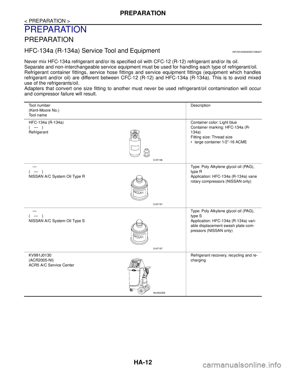
HFC-134a (R-134a) Service Tool and EquipmentINFOID:0000000001396437
Never mix HFC-134a refrigerant and/or its specified oil with CFC-12 (R-12) refrigerant and/or its oil.
Separate and non-interchangeable service equipment must be used for handling each type of refrigerant/oil.
Refrigerant container fittings, service hose fittings and service equipment fittings (equipment which handles
refrigerant and/or oil) are different between CFC-12 (R-12) and HFC-134a (R-134a). This is to avoid mixed
use of the refrigerants/oil.
Adapters that convert one size fitting to another must never be used refrigerant/oil contamination will occur
and compressor failure will result.
Tool number
(Kent-Moore No.)
Tool nameDescription
HFC-134a (R-134a)
(—)
RefrigerantContainer color: Light blue
Container marking: HFC-134a (R-
134a)
Fitting size: Thread size
large container 1/2”-16 ACME
—
(—)
NISSAN A/C System Oil Type RType: Poly Alkylene glycol oil (PAG),
type R
Application: HFC-134a (R-134a) vane
rotary compressors (NISSAN only)
—
(—)
NISSAN A/C System Oil Type SType: Poly Alkylene glycol oil (PAG),
type S
Application: HFC-134a (R-134a) vari-
able displacement swash plate com-
pressors (NISSAN only)
KV991J0130
(ACR2005-NI)
ACR5 A/C Service CenterRefrigerant recovery, recycling and re-
charging
S-NT196
S-NT197
S-NT197
WJIA0293E