relay NISSAN TIIDA 2007 Service Workshop Manual
[x] Cancel search | Manufacturer: NISSAN, Model Year: 2007, Model line: TIIDA, Model: NISSAN TIIDA 2007Pages: 5883, PDF Size: 78.95 MB
Page 564 of 5883
REAR WINDOW DEFOGGER RELAY
DEF-13
< COMPONENT DIAGNOSIS >
C
D
E
F
G
H
I
J
K
MA
B
DEF
N
O
P
Battery power supply circuit.
Fuse block (J/B).
NO >> Repair or replace the malfunctioning parts.
Component InspectionINFOID:0000000001697554
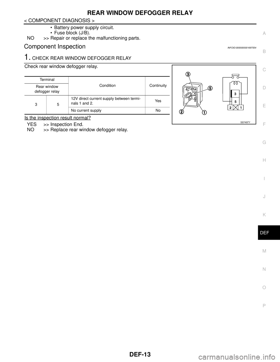
1. CHECK REAR WINDOW DEFOGGER RELAY
Check rear window defogger relay.
Is the inspection result normal?
YES >> Inspection End.
NO >> Replace rear window defogger relay.
Te r m i n a l
Condition Continuity
Rear window
defogger relay
3512V direct current supply between termi-
nals 1 and 2.Ye s
No current supply No
SEF497Y
Page 565 of 5883
DEF-14
< COMPONENT DIAGNOSIS >
REAR WINDOW DEFOGGER POWER SUPPLY AND GROUND CIRCUIT
REAR WINDOW DEFOGGER POWER SUPPLY AND GROUND CIRCUIT
DescriptionINFOID:0000000001697555
Heats the heating wire with the power supply from the rear window defogger relay to prevent the rear window
from fogging up.
Component Function CheckINFOID:0000000001697556
1. CHECK REAR WINDOW DEFOGGER
Check that the heating wire of rear window defogger is heated when turning the rear window defogger switch
ON.
Is the inspection result normal?
YES >> Rear window defogger is OK.
NO >> Refer to DEF-14, "
Diagnosis Procedure".
Diagnosis ProcedureINFOID:0000000001697557
1. CHECK POWER SUPPLY CIRCUIT
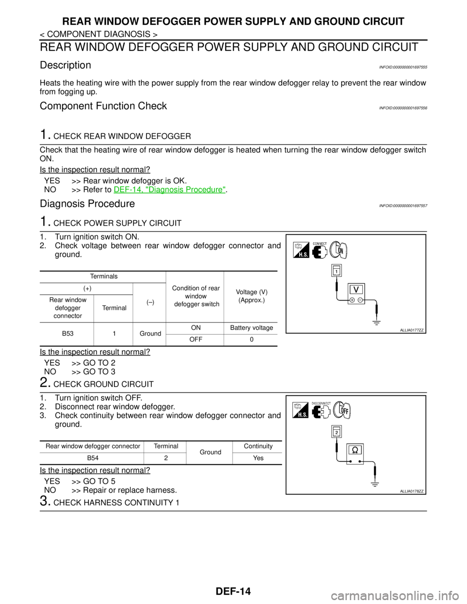
1. Turn ignition switch ON.
2. Check voltage between rear window defogger connector and
ground.
Is the inspection result normal?
YES >> GO TO 2
NO >> GO TO 3
2. CHECK GROUND CIRCUIT
1. Turn ignition switch OFF.
2. Disconnect rear window defogger.
3. Check continuity between rear window defogger connector and
ground.
Is the inspection result normal?
YES >> GO TO 5
NO >> Repair or replace harness.
3. CHECK HARNESS CONTINUITY 1
Te r m i n a l s
Condition of rear
window
defogger switchVoltage (V)
(Approx.) (+)
(–) Rear window
defogger
connectorTe r m i n a l
B53 1 GroundON Battery voltage
OFF 0
ALLIA0177ZZ
Rear window defogger connector Terminal
GroundContinuity
B54 2 Yes
ALLIA0178ZZ
Page 567 of 5883
DEF-16
< COMPONENT DIAGNOSIS >
DRIVER SIDE DOOR MIRROR DEFOGGER
DRIVER SIDE DOOR MIRROR DEFOGGER
DescriptionINFOID:0000000001697559
Heats the heating wire with the power supply from the rear window defogger relay to prevent the door mirror
from fogging up.
Component Function CheckINFOID:0000000001697560
1. CHECK DOOR MIRROR DEFOGGER LH
Check that heating wire of door mirror defogger LH is heated when turning the rear window defogger switch
ON.
Is the inspection result normal?
YES >> Door mirror defogger is OK.
NO >> Refer to DEF-16, "
Diagnosis Procedure".
Diagnosis ProcedureINFOID:0000000001697561
1. CHECK POWER SUPPLY CIRCUIT
1. Turn ignition switch OFF.
2. Disconnect door mirror LH.
3. Turn ignition switch ON.
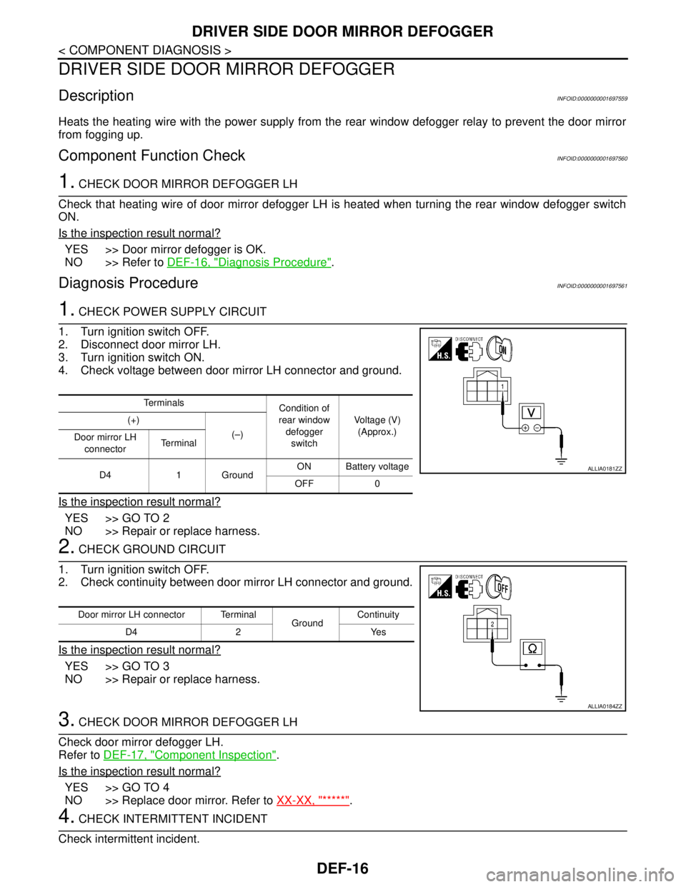
4. Check voltage between door mirror LH connector and ground.
Is the inspection result normal?
YES >> GO TO 2
NO >> Repair or replace harness.
2. CHECK GROUND CIRCUIT
1. Turn ignition switch OFF.
2. Check continuity between door mirror LH connector and ground.
Is the inspection result normal?
YES >> GO TO 3
NO >> Repair or replace harness.
3. CHECK DOOR MIRROR DEFOGGER LH
Check door mirror defogger LH.
Refer to DEF-17, "
Component Inspection".
Is the inspection result normal?
YES >> GO TO 4
NO >> Replace door mirror. Refer to XX-XX, "*****"
.
4. CHECK INTERMITTENT INCIDENT
Check intermittent incident.
Te r m i n a l s
Condition of
rear window
defogger
switchVoltage (V)
(Approx.) (+)
(–)
Door mirror LH
connectorTe r m i n a l
D4 1 GroundON Battery voltage
OFF 0
ALLIA0181ZZ
Door mirror LH connector Terminal
GroundContinuity
D4 2 Yes
ALLIA0184ZZ
Page 569 of 5883
DEF-18
< COMPONENT DIAGNOSIS >
PASSENGER SIDE DOOR MIRROR DEFOGGER
PASSENGER SIDE DOOR MIRROR DEFOGGER
DescriptionINFOID:0000000001697563
Heats the heating wire with the power supply from the rear window defogger relay to prevent the door mirror
from fogging up.
Component Function CheckINFOID:0000000001697564
1.CHECK DOOR MIRROR DEFOGGER RH
Check that the heating wire of door mirror defogger RH is heated when turning the rear window defogger
switch ON.
Is the inspection result normal?
YES >> Door mirror defogger RH is OK.
NO >> Refer to DEF-18, "
Diagnosis Procedure".
Diagnosis ProcedureINFOID:0000000001697565
1. CHECK POWER SUPPLY CIRCUIT
1. Turn ignition switch OFF.
2. Disconnect door mirror RH.
3. Turn ignition switch ON.
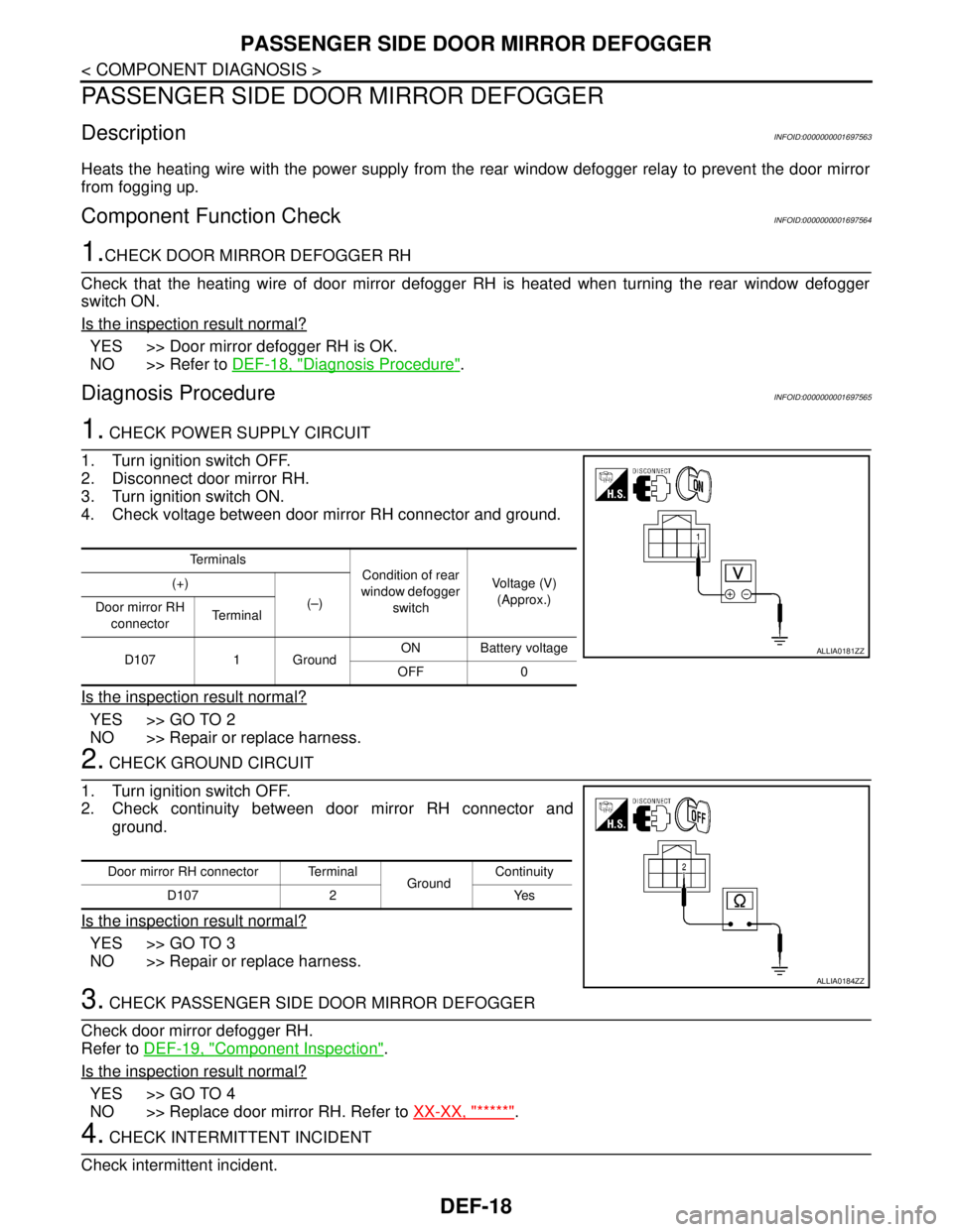
4. Check voltage between door mirror RH connector and ground.
Is the inspection result normal?
YES >> GO TO 2
NO >> Repair or replace harness.
2. CHECK GROUND CIRCUIT
1. Turn ignition switch OFF.
2. Check continuity between door mirror RH connector and
ground.
Is the inspection result normal?
YES >> GO TO 3
NO >> Repair or replace harness.
3. CHECK PASSENGER SIDE DOOR MIRROR DEFOGGER
Check door mirror defogger RH.
Refer to DEF-19, "
Component Inspection".
Is the inspection result normal?
YES >> GO TO 4
NO >> Replace door mirror RH. Refer to XX-XX, "*****"
.
4. CHECK INTERMITTENT INCIDENT
Check intermittent incident.
Te r m i n a l s
Condition of rear
window defogger
switchVoltage (V)
(Approx.) (+)
(–)
Door mirror RH
connectorTe r m i n a l
D107 1 GroundON Battery voltage
OFF 0
ALLIA0181ZZ
Door mirror RH connector Terminal
GroundContinuity
D107 2 Yes
ALLIA0184ZZ
Page 580 of 5883
REAR WINDOW DEFOGGER AND DOOR MIRROR DEFOGGER DO NOT OPER-
ATE.
DEF-29
< SYMPTOM DIAGNOSIS >
C
D
E
F
G
H
I
J
K
MA
B
DEF
N
O
P
SYMPTOM DIAGNOSIS
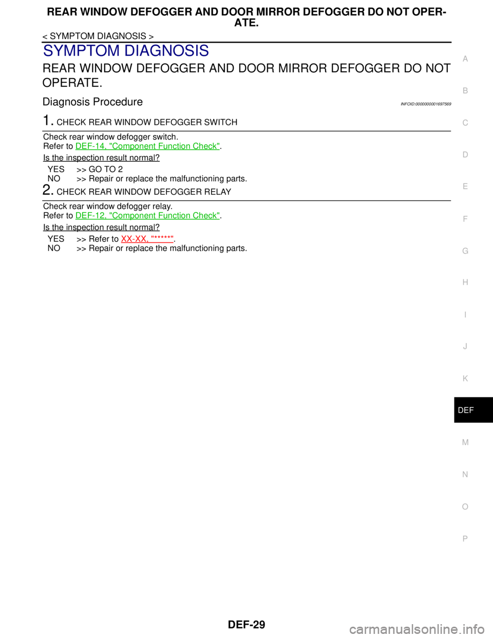
REAR WINDOW DEFOGGER AND DOOR MIRROR DEFOGGER DO NOT
OPERATE.
Diagnosis ProcedureINFOID:0000000001697569
1. CHECK REAR WINDOW DEFOGGER SWITCH
Check rear window defogger switch.
Refer to DEF-14, "
Component Function Check".
Is the inspection result normal?
YES >> GO TO 2
NO >> Repair or replace the malfunctioning parts.
2. CHECK REAR WINDOW DEFOGGER RELAY
Check rear window defogger relay.
Refer to DEF-12, "
Component Function Check".
Is the inspection result normal?
YES >> Refer to XX-XX, "*****".
NO >> Repair or replace the malfunctioning parts.
Page 1352 of 5883
EC-3
C
D
E
F
G
H
I
J
K
L
M
ECA
N
O
P
P0171 FUEL INJECTION SYSTEM FUNC-
TION .................................................................
179
DTC Logic .............................................................179
Diagnosis Procedure .............................................180
P0172 FUEL INJECTION SYSTEM FUNC-
TION .................................................................
183
DTC Logic .............................................................183
Diagnosis Procedure .............................................184
P0222, P0223 TP SENSOR .............................187
Description ............................................................187
DTC Logic .............................................................187
Diagnosis Procedure .............................................187
Component Inspection ..........................................189
Special Repair Requirement .................................189
P0300, P0301, P0302, P0303, P0304 MIS-
FIRE ..................................................................
190
DTC Logic .............................................................190
Diagnosis Procedure .............................................191
P0327, P0328 KS .............................................195
Description ............................................................195
DTC Logic .............................................................195
Diagnosis Procedure .............................................195
Component Inspection ..........................................196
P0335 CKP SENSOR (POS) ............................197
Description ............................................................197
DTC Logic .............................................................197
Diagnosis Procedure .............................................198
Component Inspection ..........................................200
P0340 CMP SENSOR (PHASE) .......................201
Description ............................................................201
DTC Logic .............................................................201
Diagnosis Procedure .............................................202
Component Inspection ..........................................203
P0420 THREE WAY CATALYST FUNCTION ..205
DTC Logic .............................................................205
Component Function Check ..................................206
Diagnosis Procedure .............................................207
P0444 EVAP CANISTER PURGE VOLUME
CONTROL SOLENOID VALVE .......................
210
Description ............................................................210
DTC Logic .............................................................210
Diagnosis Procedure .............................................210
Component Inspection ..........................................211
P0500 VSS .......................................................213
Description ............................................................213
DTC Logic .............................................................213
Component Function Check ..................................214
Diagnosis Procedure .............................................214
P0605 ECM .......................................................215
Description ............................................................215
DTC Logic .............................................................215
Diagnosis Procedure .............................................216
P1065 ECM .....................................................217
Description .............................................................217
DTC Logic ..............................................................217
Diagnosis Procedure .............................................217
P1111 IVT CONTROL SOLENOID VALVE ....219
Description .............................................................219
DTC Logic ..............................................................219
Diagnosis Procedure .............................................219
Component Inspection ...........................................220
P1121 ELECTRIC THROTTLE CONTROL
ACTUATOR .....................................................
222
Description .............................................................222
DTC Logic ..............................................................222
Diagnosis Procedure .............................................222
Special Repair Requirement ..................................223
P1122 ELECTRIC THROTTLE CONTROL
FUNCTION ......................................................
224
Description .............................................................224
DTC Logic ..............................................................224
Diagnosis Procedure .............................................224
Component Inspection ...........................................227
Special Repair Requirement ..................................227
P1124, P1126 THROTTLE CONTROL MO-
TOR RELAY ....................................................
228
Description .............................................................228
DTC Logic ..............................................................228
Diagnosis Procedure .............................................228
P1128 THROTTLE CONTROL MOTOR .........231
Description .............................................................231
DTC Logic ..............................................................231
Diagnosis Procedure .............................................231
Component Inspection ...........................................232
Special Repair Requirement ..................................232
P1143 HO2S1 ..................................................233
Description .............................................................233
DTC Logic ..............................................................233
Diagnosis Procedure .............................................234
Component Inspection ...........................................235
P1144 HO2S1 ..................................................238
Description .............................................................238
DTC Logic ..............................................................238
Diagnosis Procedure .............................................239
Component Inspection ...........................................240
P1146 HO2S2 ..................................................243
Description .............................................................243
DTC Logic ..............................................................243
Component Function Check ..................................245
Diagnosis Procedure .............................................246
Component Inspection ...........................................247
P1147 HO2S2 ..................................................250
Page 1356 of 5883
EC-7
C
D
E
F
G
H
I
J
K
L
M
ECA
N
O
P Diagnosis Procedure .............................................
503
Component Inspection ..........................................504
P0138 HO2S2 ...................................................507
Description ............................................................507
DTC Logic .............................................................507
Diagnosis Procedure .............................................508
Component Inspection ..........................................509
P0222, P0223 TP SENSOR .............................511
Description ............................................................511
DTC Logic .............................................................511
Diagnosis Procedure .............................................511
Component Inspection ..........................................513
Special Repair Requirement .................................513
P0327, P0328 KS .............................................514
Description ............................................................514
DTC Logic .............................................................514
Diagnosis Procedure .............................................514
Component Inspection ..........................................515
P0335 CKP SENSOR (POS) ............................516
Description ............................................................516
DTC Logic .............................................................516
Diagnosis Procedure .............................................517
Component Inspection ..........................................519
P0340 CMP SENSOR (PHASE) .......................520
Description ............................................................520
DTC Logic .............................................................520
Diagnosis Procedure .............................................521
Component Inspection ..........................................522
P0605 ECM .......................................................524
Description ............................................................524
DTC Logic .............................................................524
Diagnosis Procedure .............................................525
P1065 ECM .......................................................526
Description ............................................................526
DTC Logic .............................................................526
Diagnosis Procedure .............................................526
P1111 IVT CONTROL SOLENOID VALVE .....528
Description ............................................................528
DTC Logic .............................................................528
Diagnosis Procedure .............................................528
Component Inspection ..........................................529
P1121 ELECTRIC THROTTLE CONTROL
ACTUATOR ......................................................
531
Description ............................................................531
DTC Logic .............................................................531
Diagnosis Procedure .............................................531
Special Repair Requirement .................................532
P1122 ELECTRIC THROTTLE CONTROL
FUNCTION .......................................................
533
Description ............................................................533
DTC Logic .............................................................533
Diagnosis Procedure .............................................533
Component Inspection ...........................................536
Special Repair Requirement ..................................536
P1124, P1126 THROTTLE CONTROL MO-
TOR RELAY ....................................................
537
Description .............................................................537
DTC Logic ..............................................................537
Diagnosis Procedure .............................................537
P1128 THROTTLE CONTROL MOTOR .........540
Description .............................................................540
DTC Logic ..............................................................540
Diagnosis Procedure .............................................540
Component Inspection ...........................................541
Special Repair Requirement ..................................541
P1212 TCS COMMUNICATION LINE .............542
Description .............................................................542
DTC Logic ..............................................................542
Diagnosis Procedure .............................................542
P1217 ENGINE OVER TEMPERATURE ........543
DTC Logic ..............................................................543
Component Function Check ..................................543
Diagnosis Procedure .............................................544
P1225 TP SENSOR .........................................547
Description .............................................................547
DTC Logic ..............................................................547
Diagnosis Procedure .............................................547
Special Repair Requirement ..................................548
P1226 TP SENSOR .........................................549
Description .............................................................549
DTC Logic ..............................................................549
Diagnosis Procedure .............................................549
Special Repair Requirement ..................................550
P1229 SENSOR POWER SUPPLY ................551
DTC Logic ..............................................................551
Diagnosis Procedure .............................................551
P1564 ASCD STEERING SWITCH .................553
Description .............................................................553
DTC Logic ..............................................................553
Diagnosis Procedure .............................................553
Component Inspection ...........................................555
P1572 ASCD BRAKE SWITCH ......................556
Description .............................................................556
DTC Logic ..............................................................556
Component Function Check ..................................557
Diagnosis Procedure .............................................558
Component Inspection (ASCD Brake Switch) .......562
Component Inspection (ASCD Clutch Switch) ......563
Component Inspection (Stop Lamp Switch) ..........563
P1574 ASCD VEHICLE SPEED SENSOR .....564
Description .............................................................564
DTC Logic ..............................................................564
Page 1360 of 5883
EC-11
C
D
E
F
G
H
I
J
K
L
M
ECA
N
O
P
P0134 HO2S1 ...................................................823
Description ............................................................823
DTC Logic .............................................................823
Diagnosis Procedure .............................................824
Component Inspection ..........................................825
P0135 HO2S1 HEATER ...................................828
Description ............................................................828
DTC Logic .............................................................828
Diagnosis Procedure .............................................828
Component Inspection ..........................................829
P0138 HO2S2 ...................................................831
Description ............................................................831
DTC Logic .............................................................831
Diagnosis Procedure .............................................832
Component Inspection ..........................................833
P0139 HO2S2 ...................................................835
Description ............................................................835
DTC Logic .............................................................835
Component Function Check ..................................837
Diagnosis Procedure .............................................838
Component Inspection ..........................................839
P0141 HO2S2 HEATER ...................................841
Description ............................................................841
DTC Logic .............................................................841
Diagnosis Procedure .............................................841
Component Inspection ..........................................843
P0171 FUEL INJECTION SYSTEM FUNC-
TION .................................................................
844
DTC Logic .............................................................844
Diagnosis Procedure .............................................845
P0172 FUEL INJECTION SYSTEM FUNC-
TION .................................................................
848
DTC Logic .............................................................848
Diagnosis Procedure .............................................849
P0222, P0223 TP SENSOR .............................852
Description ............................................................852
DTC Logic .............................................................852
Diagnosis Procedure .............................................852
Component Inspection ..........................................854
Special Repair Requirement .................................854
P0300, P0301, P0302, P0303, P0304 MIS-
FIRE ..................................................................
855
DTC Logic .............................................................855
Diagnosis Procedure .............................................856
P0327, P0328 KS .............................................860
Description ............................................................860
DTC Logic .............................................................860
Diagnosis Procedure .............................................860
Component Inspection ..........................................861
P0335 CKP SENSOR (POS) ............................862
Description ............................................................862
DTC Logic ..............................................................862
Diagnosis Procedure .............................................863
Component Inspection ...........................................865
P0340 CMP SENSOR (PHASE) .....................866
Description .............................................................866
DTC Logic ..............................................................866
Diagnosis Procedure .............................................867
Component Inspection ...........................................868
P0420 THREE WAY CATALYST FUNCTION .870
DTC Logic ..............................................................870
Component Function Check ..................................871
Diagnosis Procedure .............................................872
P0444 EVAP CANISTER PURGE VOLUME
CONTROL SOLENOID VALVE ......................
875
Description .............................................................875
DTC Logic ..............................................................875
Diagnosis Procedure .............................................875
Component Inspection ...........................................876
P0500 VSS ......................................................878
Description .............................................................878
DTC Logic ..............................................................878
Component Function Check ..................................879
Diagnosis Procedure .............................................879
P0605 ECM .....................................................880
Description .............................................................880
DTC Logic ..............................................................880
Diagnosis Procedure .............................................881
P1111 IVT CONTROL SOLENOID VALVE ....882
Description .............................................................882
DTC Logic ..............................................................882
Diagnosis Procedure .............................................882
Component Inspection ...........................................883
P1121 ELECTRIC THROTTLE CONTROL
ACTUATOR .....................................................
885
Description .............................................................885
DTC Logic ..............................................................885
Diagnosis Procedure .............................................885
Special Repair Requirement ..................................886
P1122 ELECTRIC THROTTLE CONTROL
FUNCTION ......................................................
887
Description .............................................................887
DTC Logic ..............................................................887
Diagnosis Procedure .............................................887
Component Inspection ...........................................890
Special Repair Requirement ..................................890
P1124, P1126 THROTTLE CONTROL MO-
TOR RELAY ....................................................
891
Description .............................................................891
DTC Logic ..............................................................891
Diagnosis Procedure .............................................891
P1128 THROTTLE CONTROL MOTOR .........894
Page 1364 of 5883
EC-15
C
D
E
F
G
H
I
J
K
L
M
ECA
N
O
P Diagnosis Procedure ...........................................
1124
Component Inspection ........................................1125
P0101 MAF SENSOR .....................................1127
Description ..........................................................1127
DTC Logic ...........................................................1127
Diagnosis Procedure ...........................................1127
Component Inspection ........................................1129
P0110 IAT SENSOR .......................................1130
Description ..........................................................1130
DTC Logic ...........................................................1130
Diagnosis Procedure ...........................................1130
Component Inspection ........................................1131
P0115 ECT SENSOR .....................................1132
Description ..........................................................1132
DTC Logic ...........................................................1132
Diagnosis Procedure ...........................................1132
Component Inspection ........................................1133
P0120 ELECTRIC THROTTLE CONTROL
ACTUATOR ....................................................
1134
Description ..........................................................1134
DTC Logic ...........................................................1134
Diagnosis Procedure ...........................................1134
P0180 FPT SENSOR ......................................1136
Description ..........................................................1136
DTC Logic ...........................................................1136
Diagnosis Procedure ...........................................1136
Component Inspection ........................................1137
P0190 FRP SENSOR .....................................1138
Description ..........................................................1138
DTC Logic ...........................................................1138
Diagnosis Procedure ...........................................1138
Component Inspection ........................................1139
P0200 FUEL INJECTOR ................................1140
DTC Logic ...........................................................1140
Diagnosis Procedure ...........................................1140
Component Inspection ........................................1141
P0201, P0202, P0203, P0204 FUEL INJEC-
TOR ................................................................
1142
DTC Logic ...........................................................1142
Diagnosis Procedure ...........................................1142
Component Inspection ........................................1143
P0225 APP SENSOR .....................................1144
Description ..........................................................1144
DTC Logic ...........................................................1144
Diagnosis Procedure ...........................................1144
Component Inspection ........................................1146
P0235 TC BOOST SENSOR ..........................1147
Description ..........................................................1147
DTC Logic ...........................................................1147
Diagnosis Procedure ...........................................1147
Component Inspection ........................................1148
P0335 CKP SENSOR .....................................1149
DTC Logic ............................................................1149
Diagnosis Procedure ...........................................1149
Component Inspection .........................................1150
P0340 CMP SENSOR ....................................1151
DTC Logic ............................................................1151
Diagnosis Procedure ...........................................1151
Component Inspection .........................................1152
P0380 GLOW RELAY ....................................1154
DTC Logic ............................................................1154
Diagnosis Procedure ...........................................1154
P0381 GLOW CONTROL SYSTEM ...............1156
DTC Logic ............................................................1156
Diagnosis Procedure ...........................................1156
Component Inspection .........................................1157
P0409 EGR VOLUME CONTROL VALVE
CONTROL POSITION SENSOR ....................
1158
DTC Logic ............................................................1158
Diagnosis Procedure ...........................................1158
P0487 EGR VOLUME CONTROL VALVE ....1160
DTC Logic ............................................................1160
Diagnosis Procedure ...........................................1160
Component Inspection .........................................1161
P0488 EGR SYSTEM .....................................1162
DTC Logic ............................................................1162
Diagnosis Procedure ...........................................1162
Component Inspection .........................................1164
P0500 VSS .....................................................1165
Description ...........................................................1165
DTC Logic ............................................................1165
Diagnosis Procedure ...........................................1165
P0530 REFRIGERANT PRESSURE SENSOR
1166
Description ...........................................................1166
DTC Logic ............................................................1166
Diagnosis Procedure ...........................................1166
P0560 BATTERY VOLTAGE .........................1168
DTC Logic ............................................................1168
Diagnosis Procedure ...........................................1168
P0571 ASCD BRAKE SWITCH .....................1171
DTC Logic ............................................................1171
Diagnosis Procedure ...........................................1171
Component Inspection .........................................1172
P0575 ASCD STEERING SWITCH ................1174
Description ...........................................................1174
DTC Logic ............................................................1174
Diagnosis Procedure ...........................................1174
Component Inspection (ASCD Switch) ................1176
Component Inspection (ASCD Steering Switch) .1176
Page 1365 of 5883

EC-16
P0606 ECM .....................................................1178
Description ...........................................................1178
DTC Logic ............................................................1178
Diagnosis Procedure ...........................................1178
P0641 SENSOR POWER SUPPLY ................1180
DTC Logic ............................................................1180
Diagnosis Procedure ...........................................1180
P0651 SENSOR POWER SUPPLY ................1182
DTC Logic ............................................................1182
Diagnosis Procedure ...........................................1182
P0685 ECM RELAY ........................................1184
DTC Logic ............................................................1184
Diagnosis Procedure ...........................................1184
P1089 FUEL PUMP ........................................1186
DTC Logic ............................................................1186
Diagnosis Procedure ...........................................1186
P2101 ELECTRIC THROTTLE CONTROL
FUNCTION ......................................................
1188
Description ...........................................................1188
DTC Logic ............................................................1188
Diagnosis Procedure ...........................................1188
Component Inspection .........................................1189
P2120 APP SENSOR .....................................1191
Description ...........................................................1191
DTC Logic ............................................................1191
Diagnosis Procedure ...........................................1191
Component Inspection .........................................1193
P2226 BARO SENSOR ..................................1194
Description ...........................................................1194
DTC Logic ............................................................1194
Diagnosis Procedure ...........................................1194
P2263 TC SYSTEM ........................................1195
DTC Logic ............................................................1195
Diagnosis Procedure ...........................................1195
P2299 ACCELERATOR/BRAKE PEDAL PO-
SITION INCONSISTENCY ..............................
1198
DTC Logic ............................................................1198
Diagnosis Procedure ...........................................1198
P2413 EGR SYSTEM .....................................1202
DTC Logic ............................................................1202
Diagnosis Procedure ...........................................1202
Component Inspection .........................................1204
P2502 BATTERY VOLTAGE ..........................1205
DTC Logic ............................................................1205
Diagnosis Procedure ...........................................1205
P2610 ENGINE SAFETY STOP .....................1206
DTC Logic ............................................................1206
Diagnosis Procedure ...........................................1206
ASCD CLUTCH SWITCH ...............................1208
Description ...........................................................1208
Component Function Check ................................1208
Diagnosis Procedure ............................................1208
Component Inspection .........................................1209
ASCD INDICATOR .........................................1210
Description ...........................................................1210
Component Function Check ................................1210
Diagnosis Procedure ............................................1210
COOLING FAN ...............................................1211
Description ...........................................................1211
Component Function Check ................................1211
Diagnosis Procedure ............................................1211
Component Inspection .........................................1212
STOP LAMP SWITCH ....................................1214
Description ...........................................................1214
Component Function Check ................................1214
Diagnosis Procedure ............................................1214
Component Inspection .........................................1215
ECU DIAGNOSIS .....................................1216
ECM ................................................................1216
Reference Value ..................................................1216
Conformity Check ................................................1223
Wiring Diagram - ENGINE CONTROL SYSTEM - 1236
DTC Index ............................................................1252
SYMPTOM DIAGNOSIS ..........................1255
ENGINE CONTROL SYSTEM SYMPTOMS ..1255
Symptom Table ....................................................1255
NOT COMMUNICATION WITH THE ECM .....1256
Description ...........................................................1256
Diagnosis Procedure ............................................1256
ENGINE DOES NOT START OR STARTS
WITH DIFFICULTY .........................................
1257
Description ...........................................................1257
Diagnosis Procedure ............................................1257
STARTING DIFFICULT WITH COLD ENGINE 1259
Description ...........................................................1259
Diagnosis Procedure ............................................1259
IMPOSSIBLE TO SHUT OFF ENGINE ..........1261
Description ...........................................................1261
Diagnosis Procedure ............................................1261
ENGINE IDLE SPEED TOO HIGH .................1262
Description ...........................................................1262
Diagnosis Procedure ............................................1262
ENGINE IDLE SPEED TOO LOW OR UNSTA-
BLE .................................................................
1263
Description ...........................................................1263
Diagnosis Procedure ............................................1263
ENGINE STALLING .......................................1265