height NISSAN TIIDA 2007 Service Manual Online
[x] Cancel search | Manufacturer: NISSAN, Model Year: 2007, Model line: TIIDA, Model: NISSAN TIIDA 2007Pages: 5883, PDF Size: 78.95 MB
Page 2719 of 5883
EM-72
< ON-VEHICLE REPAIR >[HR16DE]
CAMSHAFT
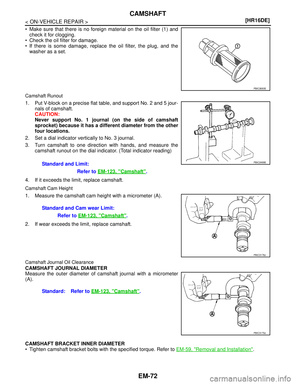
Make sure that there is no foreign material on the oil filter (1) and
check it for clogging.
Check the oil filter for damage.
If there is some damage, replace the oil filter, the plug, and the
washer as a set.
Camshaft Runout
1. Put V-block on a precise flat table, and support No. 2 and 5 jour-
nals of camshaft.
CAUTION:
Never support No. 1 journal (on the side of camshaft
sprocket) because it has a different diameter from the other
four locations.
2. Set a dial indicator vertically to No. 3 journal.
3. Turn camshaft to one direction with hands, and measure the
camshaft runout on the dial indicator. (Total indicator reading)
4. If it exceeds the limit, replace camshaft.
Camshaft Cam Height
1. Measure the camshaft cam height with a micrometer (A).
2. If wear exceeds the limit, replace camshaft.
Camshaft Journal Oil Clearance
CAMSHAFT JOURNAL DIAMETER
Measure the outer diameter of camshaft journal with a micrometer
(A).
CAMSHAFT BRACKET INNER DIAMETER
Tighten camshaft bracket bolts with the specified torque. Refer to EM-59, "
Removal and Installation".
PBIC3693E
Standard and Limit:
Refer to EM-123, "
Camshaft".
PBIC2499E
Standard and Cam wear Limit:
Refer to EM-123, "
Camshaft".
PBIC3178J
Standard: Refer to EM-123, "Camshaft".
PBIC3179J
Page 2724 of 5883
OIL SEAL
EM-77
< ON-VEHICLE REPAIR >[HR16DE]
C
D
E
F
G
H
I
J
K
L
MA
EM
N
P O
OIL SEAL
VALVE OIL SEAL
VALVE OIL SEAL : Removal and InstallationINFOID:0000000001381417
REMOVAL
1. Remove camshafts. Refer to EM-59, "Exploded View".
2. Remove valve lifters. Refer to EM-59, "
Exploded View".
3. Rotate crankshaft, and set piston whose valve oil seal is to be removed to TDC. This will prevent valve
from dropping into cylinder.
CAUTION:
When rotating crankshaft, be careful to avoid scarring front cover with timing chain.
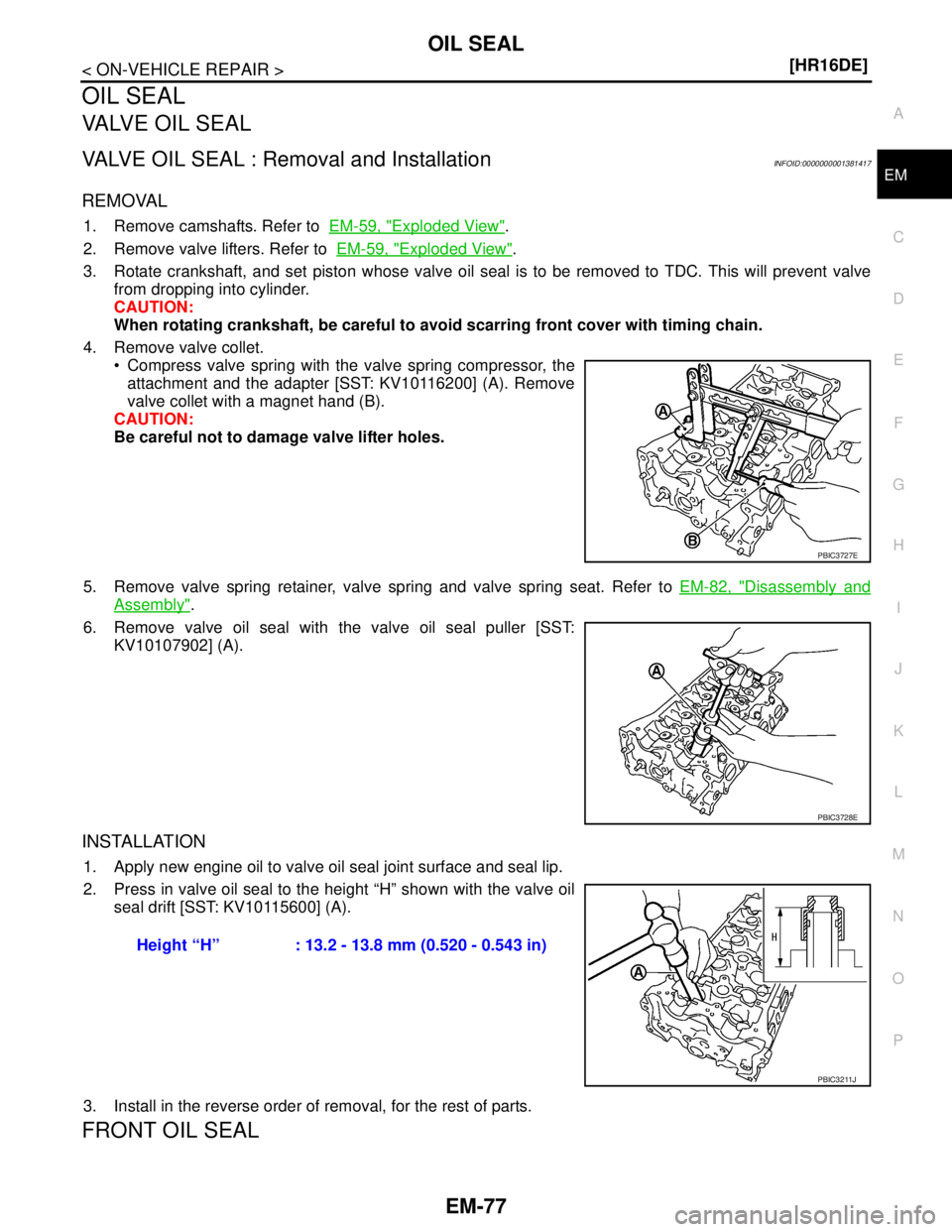
4. Remove valve collet.
Compress valve spring with the valve spring compressor, the
attachment and the adapter [SST: KV10116200] (A). Remove
valve collet with a magnet hand (B).
CAUTION:
Be careful not to damage valve lifter holes.
5. Remove valve spring retainer, valve spring and valve spring seat. Refer to EM-82, "
Disassembly and
Assembly".
6. Remove valve oil seal with the valve oil seal puller [SST:
KV10107902] (A).
INSTALLATION
1. Apply new engine oil to valve oil seal joint surface and seal lip.
2. Press in valve oil seal to the height “H” shown with the valve oil
seal drift [SST: KV10115600] (A).
3. Install in the reverse order of removal, for the rest of parts.
FRONT OIL SEAL
PBIC3727E
PBIC3728E
Height “H” : 13.2 - 13.8 mm (0.520 - 0.543 in)
PBIC3211J
Page 2725 of 5883
EM-78
< ON-VEHICLE REPAIR >[HR16DE]
OIL SEAL
FRONT OIL SEAL : Removal and Installation
INFOID:0000000001381418
REMOVAL
1. Remove the following parts:
Front fender protector (RH): Refer to EXT-22, "
Removal and Installation".
Drive belt: Refer to EM-16, "
Removal and Installation".
Crankshaft pulley: Refer to EM-50, "
Exploded View".
2. Remove front oil seal using a suitable tool.
CAUTION:
Be careful not to damage front timing chain case and crankshaft.
INSTALLATION
1. Apply new engine oil to both oil seal lip and dust seal lip of new front oil seal.
2. Install front oil seal.
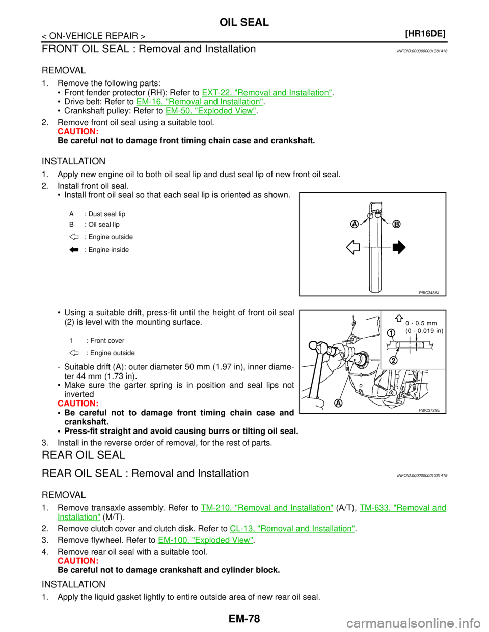
Install front oil seal so that each seal lip is oriented as shown.
Using a suitable drift, press-fit until the height of front oil seal
(2) is level with the mounting surface.
- Suitable drift (A): outer diameter 50 mm (1.97 in), inner diame-
ter 44 mm (1.73 in).
Make sure the garter spring is in position and seal lips not
inverted
CAUTION:
Be careful not to damage front timing chain case and
crankshaft.
Press-fit straight and avoid causing burrs or tilting oil seal.
3. Install in the reverse order of removal, for the rest of parts.
REAR OIL SEAL
REAR OIL SEAL : Removal and InstallationINFOID:0000000001381419
REMOVAL
1. Remove transaxle assembly. Refer to TM-210, "Removal and Installation" (A/T), TM-633, "Removal and
Installation" (M/T).
2. Remove clutch cover and clutch disk. Refer to CL-13, "
Removal and Installation".
3. Remove flywheel. Refer to EM-100, "
Exploded View".
4. Remove rear oil seal with a suitable tool.
CAUTION:
Be careful not to damage crankshaft and cylinder block.
INSTALLATION
1. Apply the liquid gasket lightly to entire outside area of new rear oil seal.
A : Dust seal lip
B: Oil seal lip
: Engine outside
: Engine inside
PBIC3485J
1 : Front cover
: Engine outside
PBIC3729E
Page 2732 of 5883
CYLINDER HEAD
EM-85
< ON-VEHICLE REPAIR >[HR16DE]
C
D
E
F
G
H
I
J
K
L
MA
EM
N
P O
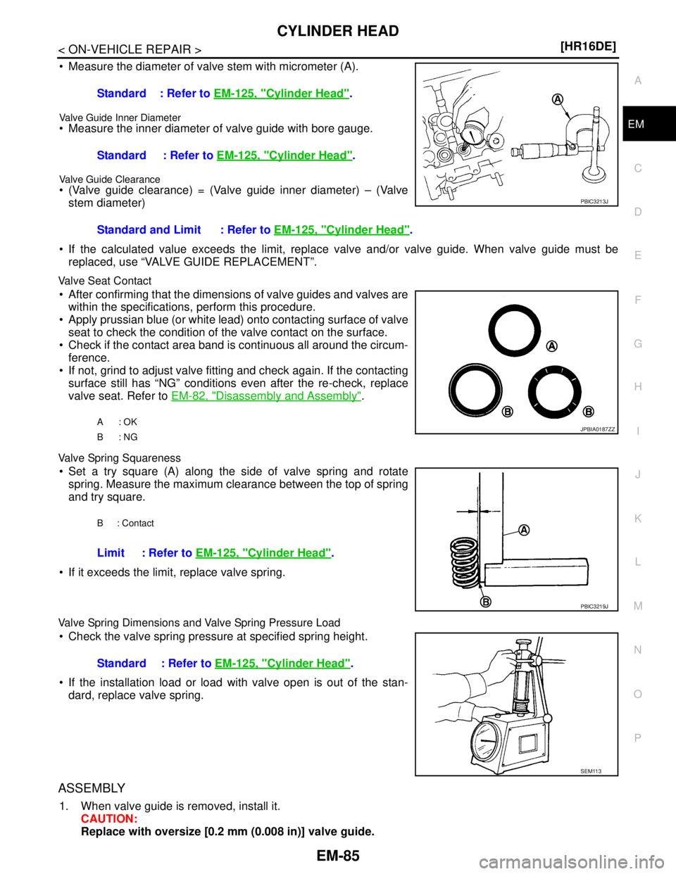
Measure the diameter of valve stem with micrometer (A).
Valve Guide Inner Diameter Measure the inner diameter of valve guide with bore gauge.
Valve Guide Clearance (Valve guide clearance) = (Valve guide inner diameter) – (Valve
stem diameter)
If the calculated value exceeds the limit, replace valve and/or valve guide. When valve guide must be
replaced, use “VALVE GUIDE REPLACEMENT”.
Valve Seat Contact
After confirming that the dimensions of valve guides and valves are
within the specifications, perform this procedure.
Apply prussian blue (or white lead) onto contacting surface of valve
seat to check the condition of the valve contact on the surface.
Check if the contact area band is continuous all around the circum-
ference.
If not, grind to adjust valve fitting and check again. If the contacting
surface still has “NG” conditions even after the re-check, replace
valve seat. Refer to EM-82, "
Disassembly and Assembly".
Valve Spring Squareness
Set a try square (A) along the side of valve spring and rotate
spring. Measure the maximum clearance between the top of spring
and try square.
If it exceeds the limit, replace valve spring.
Valve Spring Dimensions and Valve Spring Pressure Load
Check the valve spring pressure at specified spring height.
If the installation load or load with valve open is out of the stan-
dard, replace valve spring.
ASSEMBLY
1. When valve guide is removed, install it.
CAUTION:
Replace with oversize [0.2 mm (0.008 in)] valve guide.Standard : Refer to EM-125, "
Cylinder Head".
Standard : Refer to EM-125, "
Cylinder Head".
Standard and Limit : Refer to EM-125, "
Cylinder Head".
PBIC3213J
A: OK
B: NGJPBIA0187ZZ
B: Contact
Limit : Refer to EM-125, "Cylinder Head".
PBIC3219J
Standard : Refer to EM-125, "Cylinder Head".
SEM113
Page 2734 of 5883
CYLINDER HEAD
EM-87
< ON-VEHICLE REPAIR >[HR16DE]
C
D
E
F
G
H
I
J
K
L
MA
EM
N
P O
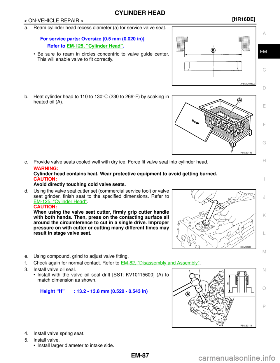
a. Ream cylinder head recess diameter (a) for service valve seat.
Be sure to ream in circles concentric to valve guide center.
This will enable valve to fit correctly.
b. Heat cylinder head to 110 to 130°C (230 to 266°F) by soaking in
heated oil (A).
c. Provide valve seats cooled well with dry ice. Force fit valve seat into cylinder head.
WARNING:
Cylinder head contains heat. Wear protective equipment to avoid getting burned.
CAUTION:
Avoid directly touching cold valve seats.
d. Using the valve seat cutter set (commercial service tool) or valve
seat grinder, finish seat to the specified dimensions. Refer to
EM-125, "
Cylinder Head".
CAUTION:
When using the valve seat cutter, firmly grip cutter handle
with both hands. Then, press on the contacting surface all
around the circumference to cut in a single drive. Improper
pressure on with cutter or cutting many different times may
result in stage valve seat.
e. Using compound, grind to adjust valve fitting.
f. Check again for normal contact. Refer to EM-82, "
Disassembly and Assembly".
3. Install valve oil seal.
Install with the valve oil seal drift [SST: KV10115600] (A) to
match dimension as shown.
4. Install valve spring seat.
5. Install valve.
Install larger diameter to intake side.For service parts: Oversize [0.5 mm (0.020 in)]
Refer to EM-125, "
Cylinder Head".
JPBIA0188ZZ
PBIC3214J
SEM934C
Height “H” : 13.2 - 13.8 mm (0.520 - 0.543 in)
PBIC3211J
Page 2761 of 5883
EM-114
< DISASSEMBLY AND ASSEMBLY >[HR16DE]
CYLINDER BLOCK
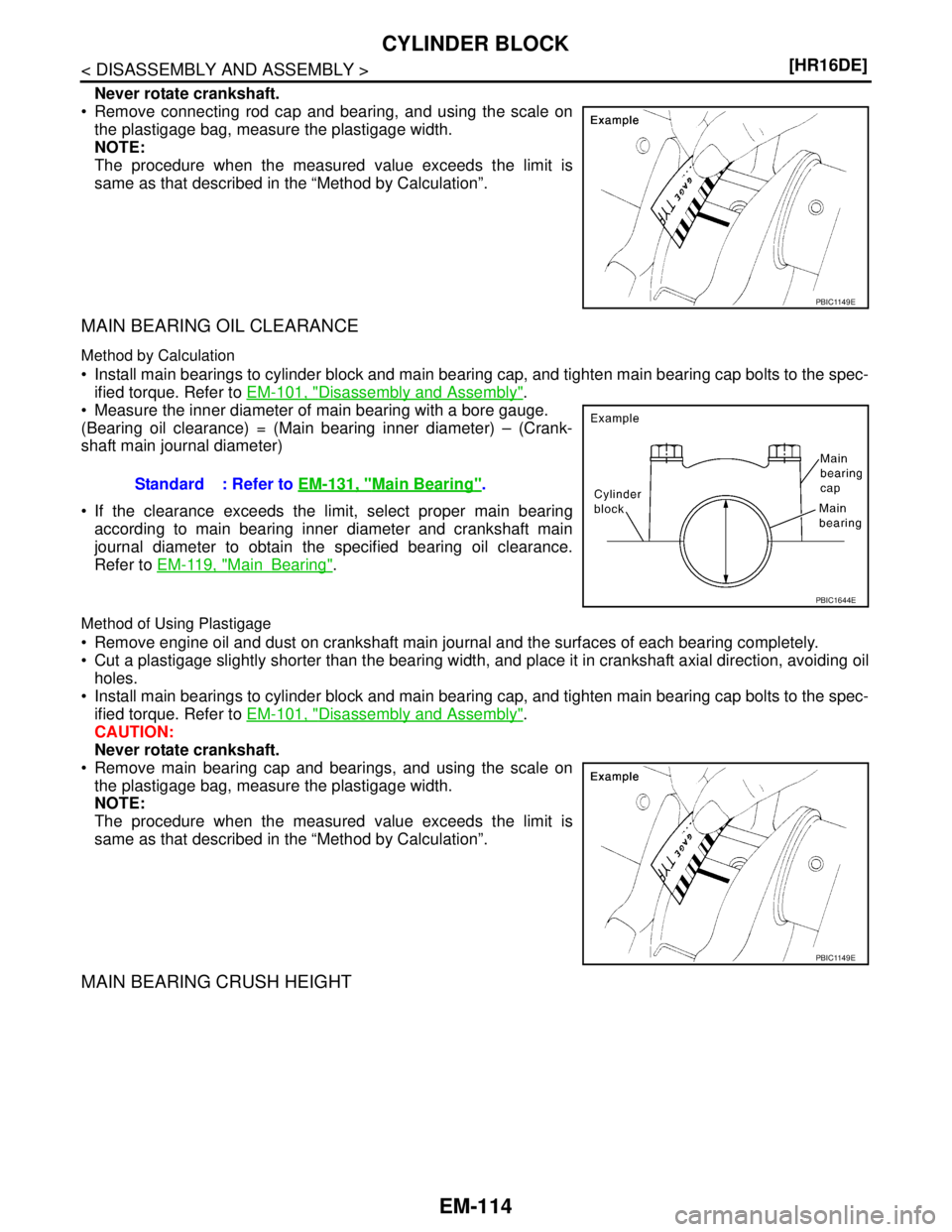
Never rotate crankshaft.
Remove connecting rod cap and bearing, and using the scale on
the plastigage bag, measure the plastigage width.
NOTE:
The procedure when the measured value exceeds the limit is
same as that described in the “Method by Calculation”.
MAIN BEARING OIL CLEARANCE
Method by Calculation
Install main bearings to cylinder block and main bearing cap, and tighten main bearing cap bolts to the spec-
ified torque. Refer to EM-101, "
Disassembly and Assembly".
Measure the inner diameter of main bearing with a bore gauge.
(Bearing oil clearance) = (Main bearing inner diameter) – (Crank-
shaft main journal diameter)
If the clearance exceeds the limit, select proper main bearing
according to main bearing inner diameter and crankshaft main
journal diameter to obtain the specified bearing oil clearance.
Refer to EM-119, "
MainBearing".
Method of Using Plastigage
Remove engine oil and dust on crankshaft main journal and the surfaces of each bearing completely.
Cut a plastigage slightly shorter than the bearing width, and place it in crankshaft axial direction, avoiding oil
holes.
Install main bearings to cylinder block and main bearing cap, and tighten main bearing cap bolts to the spec-
ified torque. Refer to EM-101, "
Disassembly and Assembly".
CAUTION:
Never rotate crankshaft.
Remove main bearing cap and bearings, and using the scale on
the plastigage bag, measure the plastigage width.
NOTE:
The procedure when the measured value exceeds the limit is
same as that described in the “Method by Calculation”.
MAIN BEARING CRUSH HEIGHT
PBIC1149E
Standard : Refer to EM-131, "Main Bearing".
PBIC1644E
PBIC1149E
Page 2762 of 5883
CYLINDER BLOCK
EM-115
< DISASSEMBLY AND ASSEMBLY >[HR16DE]
C
D
E
F
G
H
I
J
K
L
MA
EM
N
P O
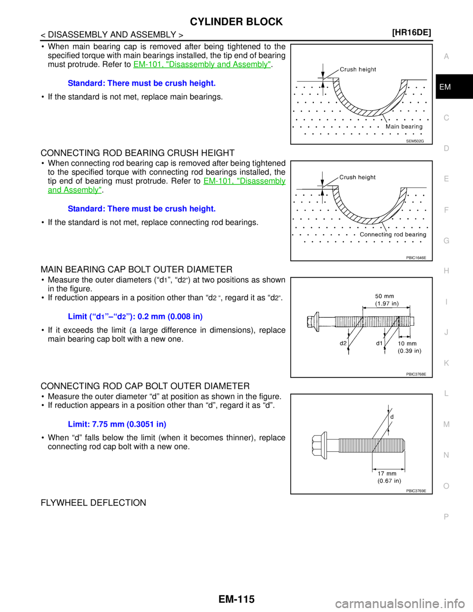
When main bearing cap is removed after being tightened to the
specified torque with main bearings installed, the tip end of bearing
must protrude. Refer to EM-101, "
Disassembly and Assembly".
If the standard is not met, replace main bearings.
CONNECTING ROD BEARING CRUSH HEIGHT
When connecting rod bearing cap is removed after being tightened
to the specified torque with connecting rod bearings installed, the
tip end of bearing must protrude. Refer to EM-101, "
Disassembly
and Assembly".
If the standard is not met, replace connecting rod bearings.
MAIN BEARING CAP BOLT OUTER DIAMETER
Measure the outer diameters (“d1”, “d2”) at two positions as shown
in the figure.
If reduction appears in a position other than “d
2 ”, regard it as “d2”.
If it exceeds the limit (a large difference in dimensions), replace
main bearing cap bolt with a new one.
CONNECTING ROD CAP BOLT OUTER DIAMETER
Measure the outer diameter “d” at position as shown in the figure.
If reduction appears in a position other than “d”, regard it as “d”.
When “d” falls below the limit (when it becomes thinner), replace
connecting rod cap bolt with a new one.
FLYWHEEL DEFLECTION
Standard: There must be crush height.
SEM502G
Standard: There must be crush height.
PBIC1646E
Limit (“d1”–“d2”): 0.2 mm (0.008 in)
PBIC3768E
Limit: 7.75 mm (0.3051 in)
PBIC3769E
Page 2770 of 5883
SERVICE DATA AND SPECIFICATIONS (SDS)
EM-123
< SERVICE DATA AND SPECIFICATIONS (SDS) [HR16DE]
C
D
E
F
G
H
I
J
K
L
MA
EM
N
P O
*: When engine is cold.
Spark PlugINFOID:0000000001381441
SPARK PLUG (PLATINUM-TIPPED TYPE)
Unit: mm (in)
Exhaust ManifoldINFOID:0000000001381442
EXHAUST MANIFOLD
Unit: mm (in)
CamshaftINFOID:0000000001381443
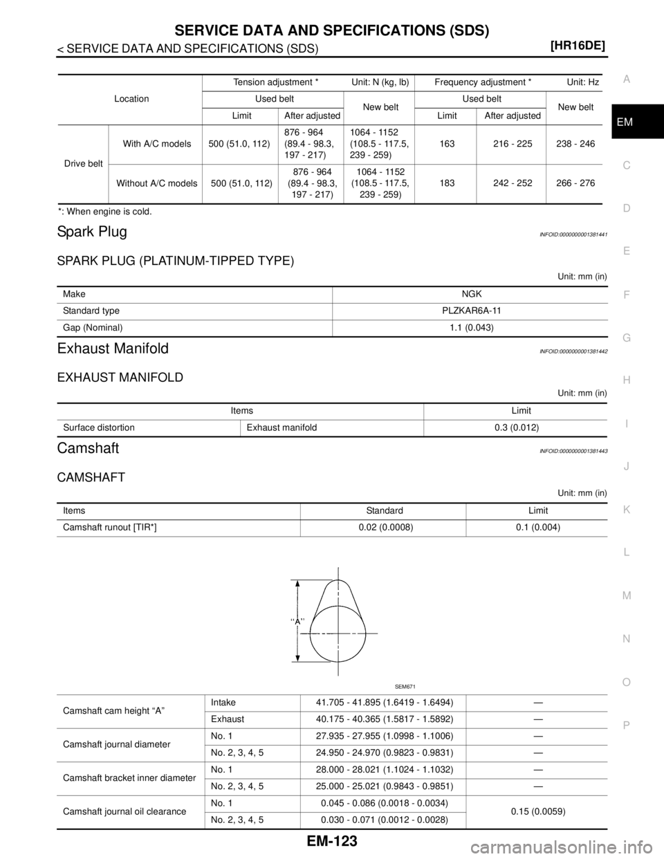
CAMSHAFT
Unit: mm (in)
Location Tension adjustment * Unit: N (kg, lb) Frequency adjustment * Unit: Hz
Used belt
New beltUsed belt
New belt
Limit After adjusted Limit After adjusted
Drive beltWith A/C models 500 (51.0, 112)876 - 964
(89.4 - 98.3,
197 - 217)1064 - 1152
(108.5 - 117.5,
239 - 259)163 216 - 225 238 - 246
Without A/C models 500 (51.0, 112)876 - 964
(89.4 - 98.3,
197 - 217)1064 - 1152
(108.5 - 117.5,
239 - 259)183 242 - 252 266 - 276
MakeNGK
Standard typePLZKAR6A-11
Gap (Nominal)1.1 (0.043)
Items Limit
Surface distortion Exhaust manifold 0.3 (0.012)
Items Standard Limit
Camshaft runout [TIR*] 0.02 (0.0008) 0.1 (0.004)
Camshaft cam height “A”Intake 41.705 - 41.895 (1.6419 - 1.6494) —
Exhaust 40.175 - 40.365 (1.5817 - 1.5892) —
Camshaft journal diameterNo. 1 27.935 - 27.955 (1.0998 - 1.1006) —
No. 2, 3, 4, 5 24.950 - 24.970 (0.9823 - 0.9831) —
Camshaft bracket inner diameterNo. 1 28.000 - 28.021 (1.1024 - 1.1032) —
No. 2, 3, 4, 5 25.000 - 25.021 (0.9843 - 0.9851) —
Camshaft journal oil clearanceNo. 1 0.045 - 0.086 (0.0018 - 0.0034)
0.15 (0.0059)
No. 2, 3, 4, 5 0.030 - 0.071 (0.0012 - 0.0028)
SEM671
Page 2772 of 5883
SERVICE DATA AND SPECIFICATIONS (SDS)
EM-125
< SERVICE DATA AND SPECIFICATIONS (SDS) [HR16DE]
C
D
E
F
G
H
I
J
K
L
MA
EM
N
P O
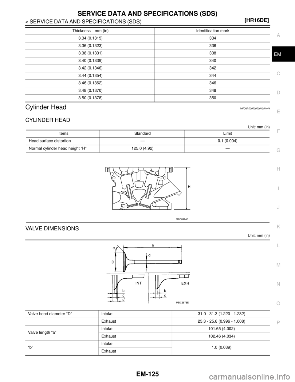
Cylinder HeadINFOID:0000000001381444
CYLINDER HEAD
Unit: mm (in)
VALVE DIMENSIONS
Unit: mm (in)
3.34 (0.1315) 334
3.36 (0.1323) 336
3.38 (0.1331) 338
3.40 (0.1339) 340
3.42 (0.1346) 342
3.44 (0.1354) 344
3.46 (0.1362) 346
3.48 (0.1370) 348
3.50 (0.1378) 350 Thickness mm (in) Identification mark
Items Standard Limit
Head surface distortion — 0.1 (0.004)
Normal cylinder head height “H” 125.0 (4.92) —
PBIC0924E
Valve head diameter “D” Intake 31.0 - 31.3 (1.220 - 1.232)
Exhaust 25.3 - 25.6 (0.996 - 1.008)
Valve length “a”Intake 101.65 (4.002)
Exhaust 102.46 (4.034)
“b”Intake
1.0 (0.039)
Exhaust
PBIC3878E
Page 2774 of 5883
SERVICE DATA AND SPECIFICATIONS (SDS)
EM-127
< SERVICE DATA AND SPECIFICATIONS (SDS) [HR16DE]
C
D
E
F
G
H
I
J
K
L
MA
EM
N
P O
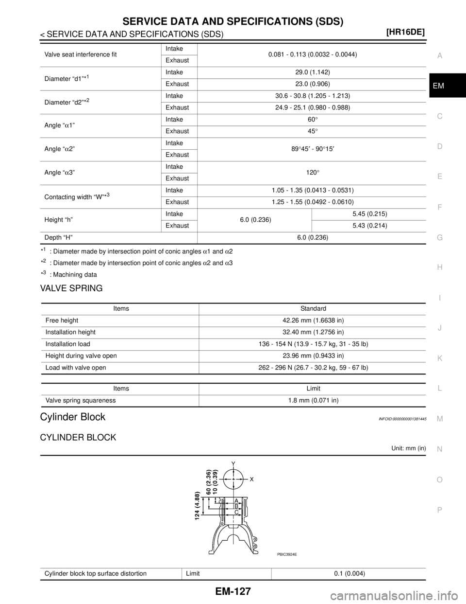
*1 : Diameter made by intersection point of conic angles α1 and α2
*
2 : Diameter made by intersection point of conic angles α2 and α3
*
3 : Machining data
VALVE SPRING
Cylinder BlockINFOID:0000000001381445
CYLINDER BLOCK
Unit: mm (in)
Valve seat interference fitIntake
0.081 - 0.113 (0.0032 - 0.0044)
Exhaust
Diameter “d1”*
1Intake 29.0 (1.142)
Exhaust 23.0 (0.906)
Diameter “d2”*
2Intake 30.6 - 30.8 (1.205 - 1.213)
Exhaust 24.9 - 25.1 (0.980 - 0.988)
Angle “α1”Intake 60°
Exhaust 45°
Angle “α2”Intake
89°45′ - 90°15′
Exhaust
Angle “α3”Intake
120°
Exhaust
Contacting width “W”*
3Intake 1.05 - 1.35 (0.0413 - 0.0531)
Exhaust 1.25 - 1.55 (0.0492 - 0.0610)
Height “h”Intake
6.0 (0.236)5.45 (0.215)
Exhaust 5.43 (0.214)
Depth “H”6.0 (0.236)
Items Standard
Free height 42.26 mm (1.6638 in)
Installation height 32.40 mm (1.2756 in)
Installation load 136 - 154 N (13.9 - 15.7 kg, 31 - 35 lb)
Height during valve open 23.96 mm (0.9433 in)
Load with valve open 262 - 296 N (26.7 - 30.2 kg, 59 - 67 lb)
Items Limit
Valve spring squareness 1.8 mm (0.071 in)
Cylinder block top surface distortion Limit 0.1 (0.004)
PBIC3924E