EXL-10 NISSAN TIIDA 2007 Service Repair Manual
[x] Cancel search | Manufacturer: NISSAN, Model Year: 2007, Model line: TIIDA, Model: NISSAN TIIDA 2007Pages: 5883, PDF Size: 78.95 MB
Page 167 of 5883
BCS-32
< COMPONENT DIAGNOSIS >
COMBINATION SWITCH INPUT CIRCUIT
YES >> GO TO 4
NO >> Replace BCM. Refer to BCS-57, "
Removal and Installation of BCM".
4. CHECK COMBINATION SWITCH
Check combination switch. Refer to BCS-34, "
Description".
Is the check result normal?
YES >> Replace BCM. Refer to BCS-57, "Removal and Installation of BCM".
NO >> Replace the combination switch (applicable parts). Refer to EXL-101, "
Removal and Installation".
Special Repair RequirementINFOID:0000000001451490
1. ADDITIONAL SERVICE WHEN REPLACING BCM
>> Refer to BCS-3, "
ADDITIONAL SERVICE WHEN REPLACING CONTROL UNIT : Special Repair
Requirement".
Page 168 of 5883
BCS
COMBINATION SWITCH OUTPUT CIRCUIT
BCS-33
< COMPONENT DIAGNOSIS >
C
D
E
F
G
H
I
J
K
L B A
O
P N
COMBINATION SWITCH OUTPUT CIRCUIT
Diagnosis ProcedureINFOID:0000000001451491
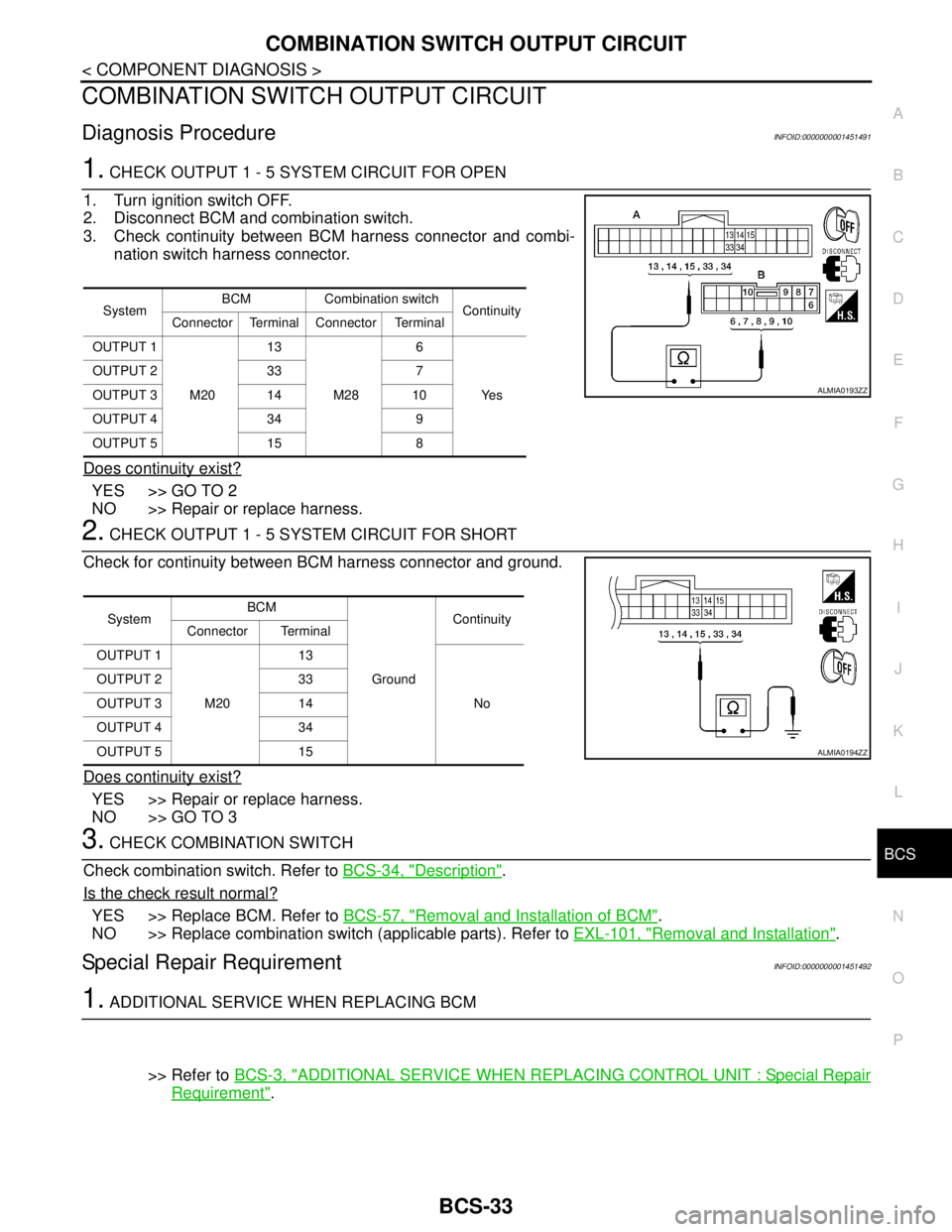
1. CHECK OUTPUT 1 - 5 SYSTEM CIRCUIT FOR OPEN
1. Turn ignition switch OFF.
2. Disconnect BCM and combination switch.
3. Check continuity between BCM harness connector and combi-
nation switch harness connector.
Does continuity exist?
YES >> GO TO 2
NO >> Repair or replace harness.
2. CHECK OUTPUT 1 - 5 SYSTEM CIRCUIT FOR SHORT
Check for continuity between BCM harness connector and ground.
Does continuity exist?
YES >> Repair or replace harness.
NO >> GO TO 3
3. CHECK COMBINATION SWITCH
Check combination switch. Refer to BCS-34, "
Description".
Is the check result normal?
YES >> Replace BCM. Refer to BCS-57, "Removal and Installation of BCM".
NO >> Replace combination switch (applicable parts). Refer to EXL-101, "
Removal and Installation".
Special Repair RequirementINFOID:0000000001451492
1. ADDITIONAL SERVICE WHEN REPLACING BCM
>> Refer to BCS-3, "
ADDITIONAL SERVICE WHEN REPLACING CONTROL UNIT : Special Repair
Requirement".
SystemBCM Combination switch
Continuity
Connector Terminal Connector Terminal
OUTPUT 1
M2013
M286
Ye s OUTPUT 2 33 7
OUTPUT 3 14 10
OUTPUT 4 34 9
OUTPUT 5 15 8
ALMIA0193ZZ
SystemBCM
GroundContinuity
Connector Terminal
OUTPUT 1
M2013
No OUTPUT 2 33
OUTPUT 3 14
OUTPUT 4 34
OUTPUT 5 15
ALMIA0194ZZ
Page 169 of 5883
BCS-34
< COMPONENT DIAGNOSIS >
COMBINATION SWITCH
COMBINATION SWITCH
DescriptionINFOID:0000000001451493
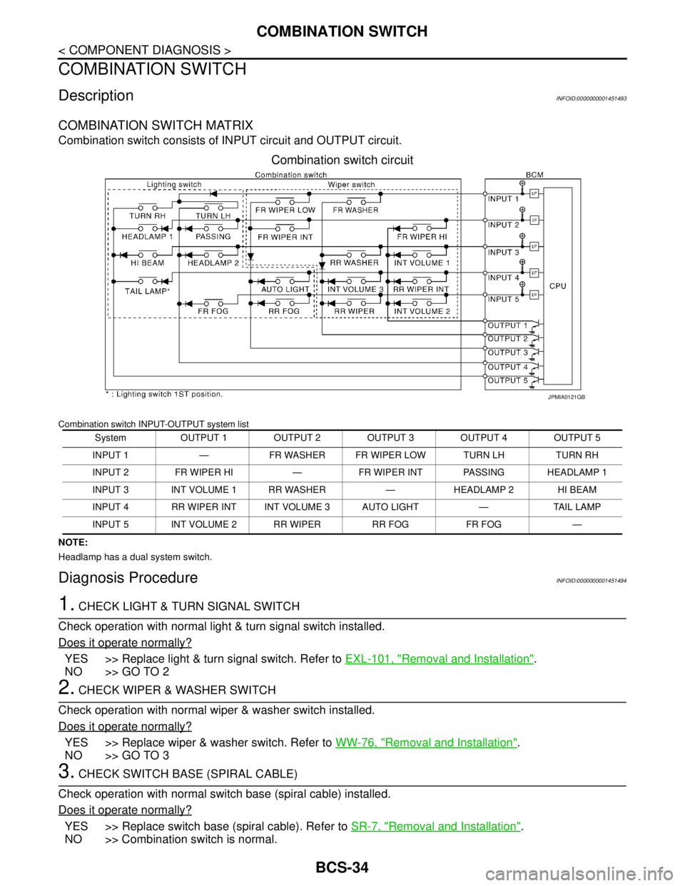
COMBINATION SWITCH MATRIX
Combination switch consists of INPUT circuit and OUTPUT circuit.
Combination switch circuit
Combination switch INPUT-OUTPUT system list
NOTE:
Headlamp has a dual system switch.
Diagnosis ProcedureINFOID:0000000001451494
1. CHECK LIGHT & TURN SIGNAL SWITCH
Check operation with normal light & turn signal switch installed.
Does it operate normally?
YES >> Replace light & turn signal switch. Refer to EXL-101, "Removal and Installation".
NO >> GO TO 2
2. CHECK WIPER & WASHER SWITCH
Check operation with normal wiper & washer switch installed.
Does it operate normally?
YES >> Replace wiper & washer switch. Refer to WW-76, "Removal and Installation".
NO >> GO TO 3
3. CHECK SWITCH BASE (SPIRAL CABLE)
Check operation with normal switch base (spiral cable) installed.
Does it operate normally?
YES >> Replace switch base (spiral cable). Refer to SR-7, "Removal and Installation".
NO >> Combination switch is normal.
System OUTPUT 1 OUTPUT 2 OUTPUT 3 OUTPUT 4 OUTPUT 5
INPUT 1 — FR WASHER FR WIPER LOW TURN LH TURN RH
INPUT 2 FR WIPER HI — FR WIPER INT PASSING HEADLAMP 1
INPUT 3 INT VOLUME 1 RR WASHER — HEADLAMP 2 HI BEAM
INPUT 4 RR WIPER INT INT VOLUME 3 AUTO LIGHT — TAIL LAMP
INPUT 5 INT VOLUME 2 RR WIPER RR FOG FR FOG —
JPMIA0121GB
Page 1661 of 5883
![NISSAN TIIDA 2007 Service Repair Manual EC-312
< COMPONENT DIAGNOSIS >[HR16DE (WITH EURO-OBD)]
ELECTRICAL LOAD SIGNAL
>> INSPECTION END
3.CHECK HEADLAMP SYSTEM
Refer to EXL-10, "
System Diagram" (XENON TYPE) or EXL-8, "System Diagram" (HALO](/img/5/57395/w960_57395-1660.png "NISSAN TIIDA 2007 Service Repair Manual EC-312
< COMPONENT DIAGNOSIS >[HR16DE (WITH EURO-OBD)]
ELECTRICAL LOAD SIGNAL
>> INSPECTION END
3.CHECK HEADLAMP SYSTEM
Refer to EXL-10, \"
System Diagram\" (XENON TYPE) or EXL-8, \"System Diagram\" (HALO")
EC-312
< COMPONENT DIAGNOSIS >[HR16DE (WITH EURO-OBD)]
ELECTRICAL LOAD SIGNAL
>> INSPECTION END
3.CHECK HEADLAMP SYSTEM
Refer to EXL-10, "
System Diagram" (XENON TYPE) or EXL-8, "System Diagram" (HALOGEN TYPE).
>> INSPECTION END
4.CHECK HEATER FAN CONTROL SYSTEM
Refer to HAC-118, "
System Description" (without NAVI system) or HAC-232, "System Description" (with NAVI
system).
>> INSPECTION END
Page 1947 of 5883
![NISSAN TIIDA 2007 Service Repair Manual EC-598
< COMPONENT DIAGNOSIS >[HR16DE (WITHOUT EURO-OBD)]
ELECTRICAL LOAD SIGNAL
>> INSPECTION END
3.CHECK HEADLAMP SYSTEM
Refer to EXL-10, "
System Diagram" (XENON TYPE) or EXL-8, "System Diagram" (H](/img/5/57395/w960_57395-1946.png "NISSAN TIIDA 2007 Service Repair Manual EC-598
< COMPONENT DIAGNOSIS >[HR16DE (WITHOUT EURO-OBD)]
ELECTRICAL LOAD SIGNAL
>> INSPECTION END
3.CHECK HEADLAMP SYSTEM
Refer to EXL-10, \"
System Diagram\" (XENON TYPE) or EXL-8, \"System Diagram\" (H")
EC-598
< COMPONENT DIAGNOSIS >[HR16DE (WITHOUT EURO-OBD)]
ELECTRICAL LOAD SIGNAL
>> INSPECTION END
3.CHECK HEADLAMP SYSTEM
Refer to EXL-10, "
System Diagram" (XENON TYPE) or EXL-8, "System Diagram" (HALOGEN TYPE).
>> INSPECTION END
4.CHECK HEATER FAN CONTROL SYSTEM
Refer to HAC-118, "
System Description" (without NAVI system) or HAC-232, "System Description" (with NAVI
system).
>> INSPECTION END
Page 2323 of 5883
![NISSAN TIIDA 2007 Service Repair Manual EC-974
< COMPONENT DIAGNOSIS >[MR18DE]
ELECTRICAL LOAD SIGNAL
>> INSPECTION END
3.CHECK HEADLAMP SYSTEM
Refer to EXL-10, "
System Diagram" (XENON TYPE) or EXL-8, "System Diagram" (HALOGEN TYPE).
>> IN](/img/5/57395/w960_57395-2322.png "NISSAN TIIDA 2007 Service Repair Manual EC-974
< COMPONENT DIAGNOSIS >[MR18DE]
ELECTRICAL LOAD SIGNAL
>> INSPECTION END
3.CHECK HEADLAMP SYSTEM
Refer to EXL-10, \"
System Diagram\" (XENON TYPE) or EXL-8, \"System Diagram\" (HALOGEN TYPE).
>> IN")
EC-974
< COMPONENT DIAGNOSIS >[MR18DE]
ELECTRICAL LOAD SIGNAL
>> INSPECTION END
3.CHECK HEADLAMP SYSTEM
Refer to EXL-10, "
System Diagram" (XENON TYPE) or EXL-8, "System Diagram" (HALOGEN TYPE).
>> INSPECTION END
4.CHECK HEATER FAN CONTROL SYSTEM
Refer to GI-55, "
Intermittent Incident".
>> INSPECTION END
Page 3011 of 5883
EXL-10
< FUNCTION DIAGNOSIS >
HEADLAMP (XENON)
HEADLAMP (XENON)
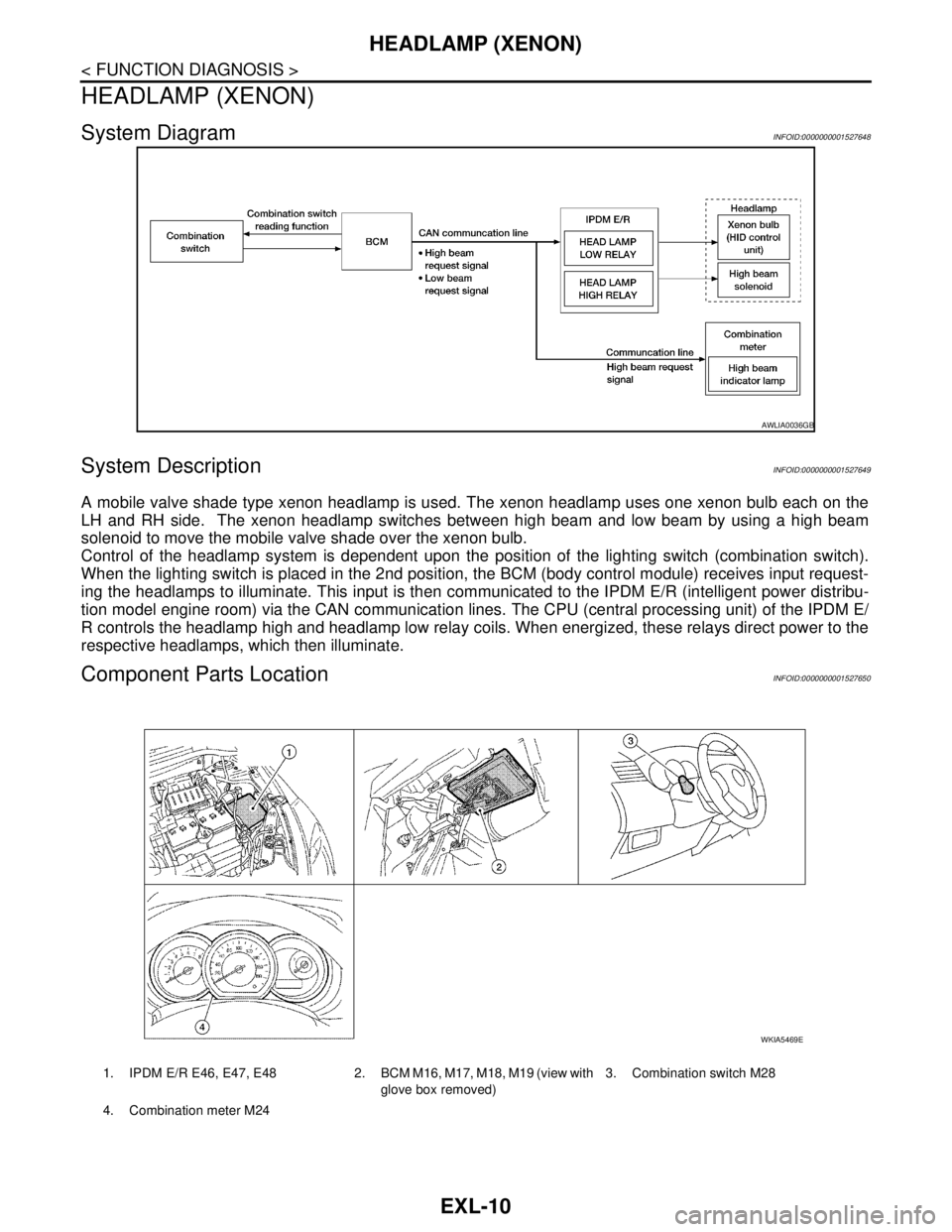
System DiagramINFOID:0000000001527648
System DescriptionINFOID:0000000001527649
A mobile valve shade type xenon headlamp is used. The xenon headlamp uses one xenon bulb each on the
LH and RH side. The xenon headlamp switches between high beam and low beam by using a high beam
solenoid to move the mobile valve shade over the xenon bulb.
Control of the headlamp system is dependent upon the position of the lighting switch (combination switch).
When the lighting switch is placed in the 2nd position, the BCM (body control module) receives input request-
ing the headlamps to illuminate. This input is then communicated to the IPDM E/R (intelligent power distribu-
tion model engine room) via the CAN communication lines. The CPU (central processing unit) of the IPDM E/
R controls the headlamp high and headlamp low relay coils. When energized, these relays direct power to the
respective headlamps, which then illuminate.
Component Parts LocationINFOID:0000000001527650
AWLIA0036GB
1. IPDM E/R E46, E47, E48 2. BCM M16, M17, M18, M19 (view with
glove box removed)3. Combination switch M28
4. Combination meter M24
WKIA5469E
Page 3101 of 5883
EXL-100
< ON-VEHICLE REPAIR >
REAR FOG LAMP
REAR FOG LAMP
Bulb ReplacementINFOID:0000000001530536
1. Remove the clips for the rear bumper fascia lower side. Refer to EXT-17, "Removal and Installation -
Sedan".
2. Disconnect the rear fog lamp connector.
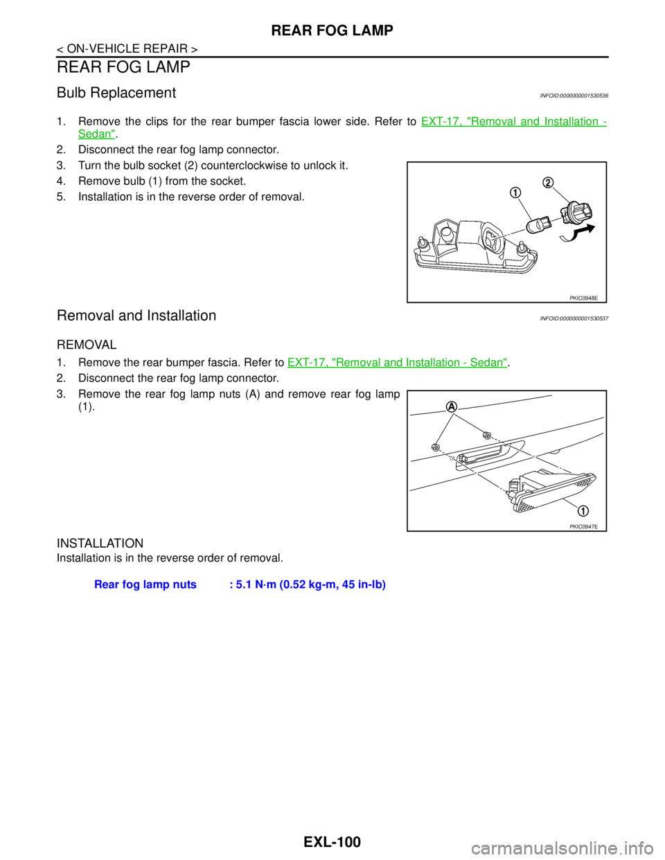
3. Turn the bulb socket (2) counterclockwise to unlock it.
4. Remove bulb (1) from the socket.
5. Installation is in the reverse order of removal.
Removal and InstallationINFOID:0000000001530537
REMOVAL
1. Remove the rear bumper fascia. Refer to EXT-17, "Removal and Installation - Sedan".
2. Disconnect the rear fog lamp connector.
3. Remove the rear fog lamp nuts (A) and remove rear fog lamp
(1).
INSTALLATION
Installation is in the reverse order of removal.
PKIC0948E
PKIC0947E
Rear fog lamp nuts : 5.1 N·m (0.52 kg-m, 45 in-lb)
Page 3102 of 5883
LIGHTING & TURN SIGNAL SWITCH
EXL-101
< ON-VEHICLE REPAIR >
C
D
E
F
G
H
I
J
K
MA
B
EXL
N
O
P
LIGHTING & TURN SIGNAL SWITCH
Removal and InstallationINFOID:0000000001529304
NOTE:
The lighting and turn signal switch is located on the LH side of the steering column for both the LHD and RHD
models.
REMOVAL
1. Remove the upper and lower steering column covers. Refer to IP-11, "Removal and Installation".
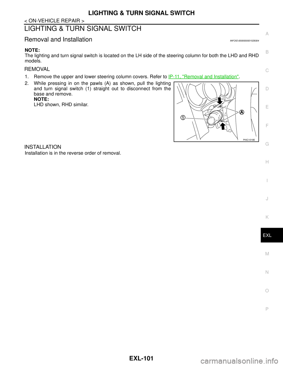
2. While pressing in on the pawls (A) as shown, pull the lighting
and turn signal switch (1) straight out to disconnect from the
base and remove.
NOTE:
LHD shown, RHD similar.
INSTALLATION
Installation is in the reverse order of removal.
PKIC1018E
Page 3103 of 5883
EXL-102
< ON-VEHICLE REPAIR >
HAZARD SWITCH
HAZARD SWITCH
Removal and InstallationINFOID:0000000001529305
REMOVAL
1. Remove the cluster lid C. Refer to IP-11, "Removal and Installation".
2. Disconnect the hazard switch connector.
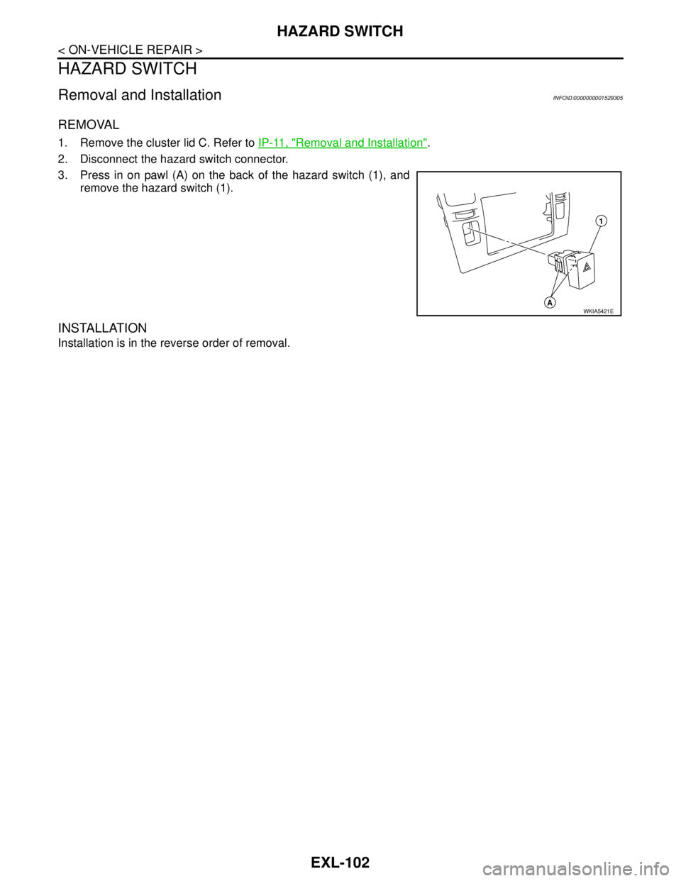
3. Press in on pawl (A) on the back of the hazard switch (1), and
remove the hazard switch (1).
INSTALLATION
Installation is in the reverse order of removal.
WKIA5421E