Gear oil NISSAN TIIDA 2007 Service Repair Manual
[x] Cancel search | Manufacturer: NISSAN, Model Year: 2007, Model line: TIIDA, Model: NISSAN TIIDA 2007Pages: 5883, PDF Size: 78.95 MB
Page 1396 of 5883
ELECTRIC IGNITION SYSTEM
EC-47
< FUNCTION DIAGNOSIS >[HR16DE (WITH EURO-OBD)]
C
D
E
F
G
H
I
J
K
L
MA
EC
N
P O
ELECTRIC IGNITION SYSTEM
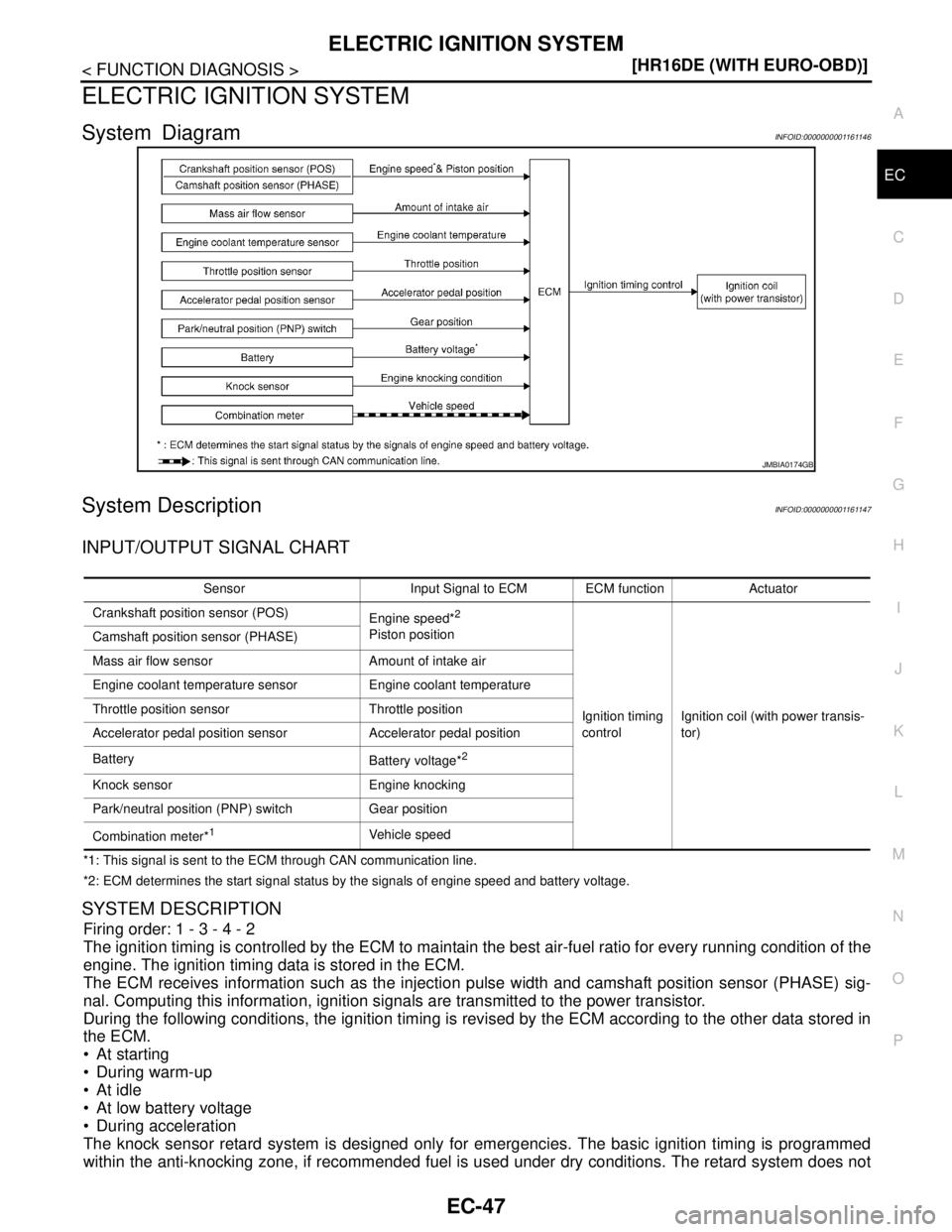
System DiagramINFOID:0000000001161146
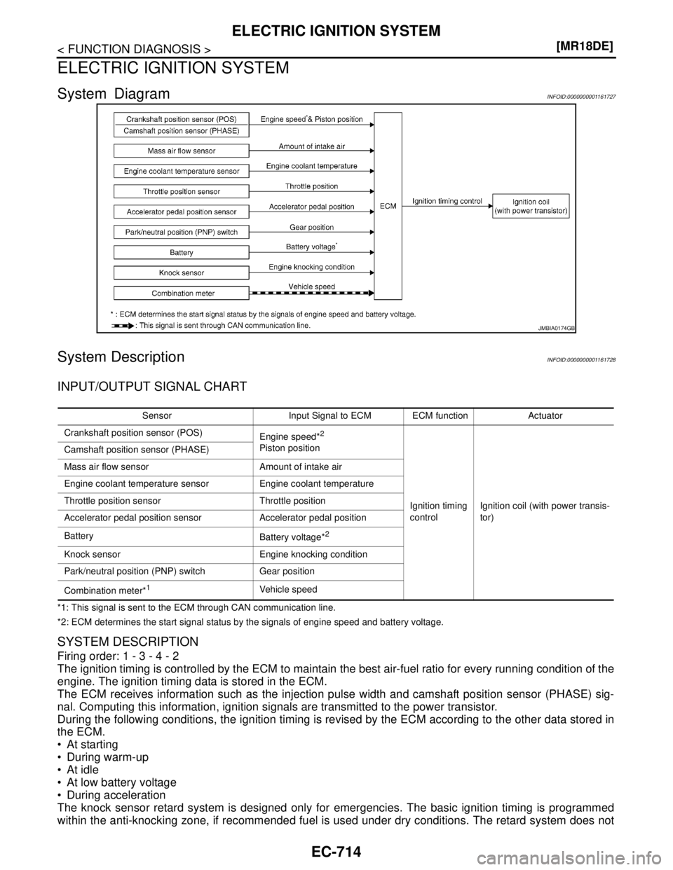
System DescriptionINFOID:0000000001161147
INPUT/OUTPUT SIGNAL CHART
*1: This signal is sent to the ECM through CAN communication line.
*2: ECM determines the start signal status by the signals of engine speed and battery voltage.
SYSTEM DESCRIPTION
Firing order: 1 - 3 - 4 - 2
The ignition timing is controlled by the ECM to maintain the best air-fuel ratio for every running condition of the
engine. The ignition timing data is stored in the ECM.
The ECM receives information such as the injection pulse width and camshaft position sensor (PHASE) sig-
nal. Computing this information, ignition signals are transmitted to the power transistor.
During the following conditions, the ignition timing is revised by the ECM according to the other data stored in
the ECM.
At starting
During warm-up
At idle
At low battery voltage
During acceleration
The knock sensor retard system is designed only for emergencies. The basic ignition timing is programmed
within the anti-knocking zone, if recommended fuel is used under dry conditions. The retard system does not
JMBIA0174GB
Sensor Input Signal to ECM ECM function Actuator
Crankshaft position sensor (POS)
Engine speed*
2
Piston position
Ignition timing
controlIgnition coil (with power transis-
tor) Camshaft position sensor (PHASE)
Mass air flow sensor Amount of intake air
Engine coolant temperature sensor Engine coolant temperature
Throttle position sensor Throttle position
Accelerator pedal position sensor Accelerator pedal position
Battery
Battery voltage*
2
Knock sensor Engine knocking
Park/neutral position (PNP) switch Gear position
Combination meter*
1Vehicle speed
Page 1546 of 5883
P0335 CKP SENSOR (POS)
EC-197
< COMPONENT DIAGNOSIS >[HR16DE (WITH EURO-OBD)]
C
D
E
F
G
H
I
J
K
L
MA
EC
N
P O
P0335 CKP SENSOR (POS)
DescriptionINFOID:0000000001670960
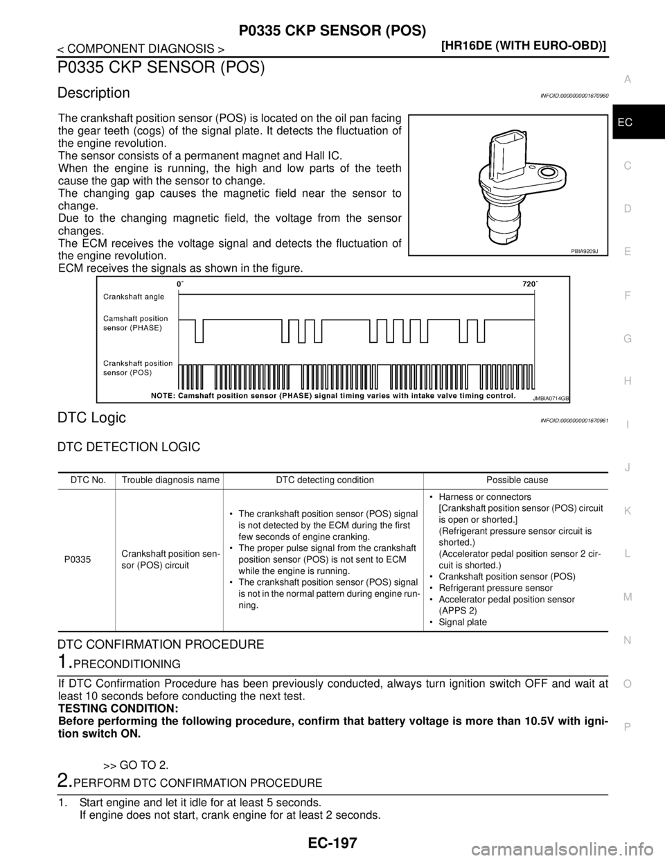
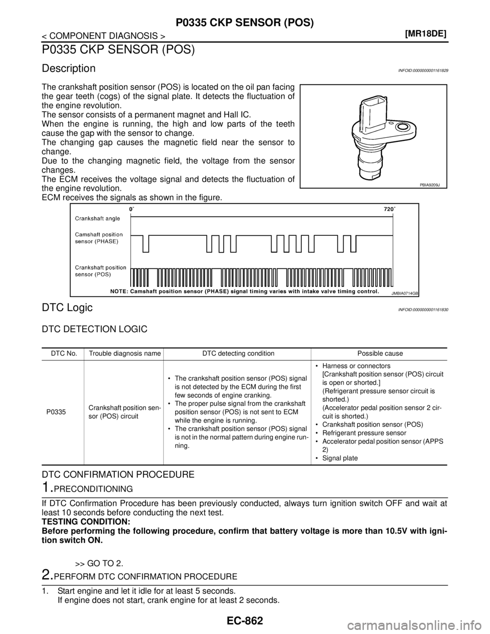
The crankshaft position sensor (POS) is located on the oil pan facing
the gear teeth (cogs) of the signal plate. It detects the fluctuation of
the engine revolution.
The sensor consists of a permanent magnet and Hall IC.
When the engine is running, the high and low parts of the teeth
cause the gap with the sensor to change.
The changing gap causes the magnetic field near the sensor to
change.
Due to the changing magnetic field, the voltage from the sensor
changes.
The ECM receives the voltage signal and detects the fluctuation of
the engine revolution.
ECM receives the signals as shown in the figure.
DTC LogicINFOID:0000000001670961
DTC DETECTION LOGIC
DTC CONFIRMATION PROCEDURE
1.PRECONDITIONING
If DTC Confirmation Procedure has been previously conducted, always turn ignition switch OFF and wait at
least 10 seconds before conducting the next test.
TESTING CONDITION:
Before performing the following procedure, confirm that battery voltage is more than 10.5V with igni-
tion switch ON.
>> GO TO 2.
2.PERFORM DTC CONFIRMATION PROCEDURE
1. Start engine and let it idle for at least 5 seconds.
If engine does not start, crank engine for at least 2 seconds.
PBIA9209J
JMBIA0714GB
DTC No. Trouble diagnosis name DTC detecting condition Possible cause
P0335Crankshaft position sen-
sor (POS) circuit The crankshaft position sensor (POS) signal
is not detected by the ECM during the first
few seconds of engine cranking.
The proper pulse signal from the crankshaft
position sensor (POS) is not sent to ECM
while the engine is running.
The crankshaft position sensor (POS) signal
is not in the normal pattern during engine run-
ning. Harness or connectors
[Crankshaft position sensor (POS) circuit
is open or shorted.]
(Refrigerant pressure sensor circuit is
shorted.)
(Accelerator pedal position sensor 2 cir-
cuit is shorted.)
Crankshaft position sensor (POS)
Refrigerant pressure sensor
Accelerator pedal position sensor
(APPS 2)
Signal plate
Page 1759 of 5883
EC-410
< FUNCTION DIAGNOSIS >[HR16DE (WITHOUT EURO-OBD)]
ELECTRIC IGNITION SYSTEM
ELECTRIC IGNITION SYSTEM
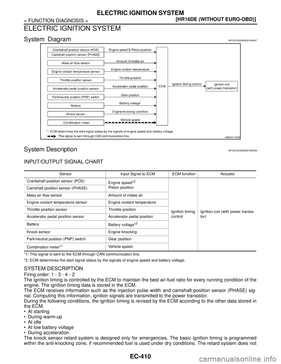
System DiagramINFOID:0000000001693467
System DescriptionINFOID:0000000001693468
INPUT/OUTPUT SIGNAL CHART
*1: This signal is sent to the ECM through CAN communication line.
*2: ECM determines the start signal status by the signals of engine speed and battery voltage.
SYSTEM DESCRIPTION
Firing order: 1 - 3 - 4 - 2
The ignition timing is controlled by the ECM to maintain the best air-fuel ratio for every running condition of the
engine. The ignition timing data is stored in the ECM.
The ECM receives information such as the injection pulse width and camshaft position sensor (PHASE) sig-
nal. Computing this information, ignition signals are transmitted to the power transistor.
During the following conditions, the ignition timing is revised by the ECM according to the other data stored in
the ECM.
At starting
During warm-up
At idle
At low battery voltage
During acceleration
The knock sensor retard system is designed only for emergencies. The basic ignition timing is programmed
within the anti-knocking zone, if recommended fuel is used under dry conditions. The retard system does not
JMBIA0174GB
Sensor Input Signal to ECM ECM function Actuator
Crankshaft position sensor (POS)
Engine speed*
2
Piston position
Ignition timing
controlIgnition coil (with power transis-
tor) Camshaft position sensor (PHASE)
Mass air flow sensor Amount of intake air
Engine coolant temperature sensor Engine coolant temperature
Throttle position sensor Throttle position
Accelerator pedal position sensor Accelerator pedal position
Battery
Battery voltage*
2
Knock sensor Engine knocking
Park/neutral position (PNP) switch Gear position
Combination meter*
1Vehicle speed
Page 1865 of 5883
EC-516
< COMPONENT DIAGNOSIS >[HR16DE (WITHOUT EURO-OBD)]
P0335 CKP SENSOR (POS)
P0335 CKP SENSOR (POS)
DescriptionINFOID:0000000001693295
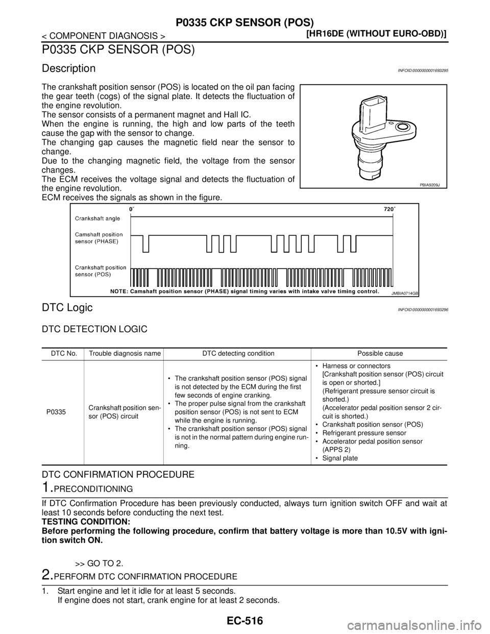
The crankshaft position sensor (POS) is located on the oil pan facing
the gear teeth (cogs) of the signal plate. It detects the fluctuation of
the engine revolution.
The sensor consists of a permanent magnet and Hall IC.
When the engine is running, the high and low parts of the teeth
cause the gap with the sensor to change.
The changing gap causes the magnetic field near the sensor to
change.
Due to the changing magnetic field, the voltage from the sensor
changes.
The ECM receives the voltage signal and detects the fluctuation of
the engine revolution.
ECM receives the signals as shown in the figure.
DTC LogicINFOID:0000000001693296
DTC DETECTION LOGIC
DTC CONFIRMATION PROCEDURE
1.PRECONDITIONING
If DTC Confirmation Procedure has been previously conducted, always turn ignition switch OFF and wait at
least 10 seconds before conducting the next test.
TESTING CONDITION:
Before performing the following procedure, confirm that battery voltage is more than 10.5V with igni-
tion switch ON.
>> GO TO 2.
2.PERFORM DTC CONFIRMATION PROCEDURE
1. Start engine and let it idle for at least 5 seconds.
If engine does not start, crank engine for at least 2 seconds.
PBIA9209J
JMBIA0714GB
DTC No. Trouble diagnosis name DTC detecting condition Possible cause
P0335Crankshaft position sen-
sor (POS) circuit The crankshaft position sensor (POS) signal
is not detected by the ECM during the first
few seconds of engine cranking.
The proper pulse signal from the crankshaft
position sensor (POS) is not sent to ECM
while the engine is running.
The crankshaft position sensor (POS) signal
is not in the normal pattern during engine run-
ning. Harness or connectors
[Crankshaft position sensor (POS) circuit
is open or shorted.]
(Refrigerant pressure sensor circuit is
shorted.)
(Accelerator pedal position sensor 2 cir-
cuit is shorted.)
Crankshaft position sensor (POS)
Refrigerant pressure sensor
Accelerator pedal position sensor
(APPS 2)
Signal plate
Page 2063 of 5883
EC-714
< FUNCTION DIAGNOSIS >[MR18DE]
ELECTRIC IGNITION SYSTEM
ELECTRIC IGNITION SYSTEM
System DiagramINFOID:0000000001161727
System DescriptionINFOID:0000000001161728
INPUT/OUTPUT SIGNAL CHART
*1: This signal is sent to the ECM through CAN communication line.
*2: ECM determines the start signal status by the signals of engine speed and battery voltage.
SYSTEM DESCRIPTION
Firing order: 1 - 3 - 4 - 2
The ignition timing is controlled by the ECM to maintain the best air-fuel ratio for every running condition of the
engine. The ignition timing data is stored in the ECM.
The ECM receives information such as the injection pulse width and camshaft position sensor (PHASE) sig-
nal. Computing this information, ignition signals are transmitted to the power transistor.
During the following conditions, the ignition timing is revised by the ECM according to the other data stored in
the ECM.
At starting
During warm-up
At idle
At low battery voltage
During acceleration
The knock sensor retard system is designed only for emergencies. The basic ignition timing is programmed
within the anti-knocking zone, if recommended fuel is used under dry conditions. The retard system does not
JMBIA0174GB
Sensor Input Signal to ECM ECM function Actuator
Crankshaft position sensor (POS)
Engine speed*
2
Piston position
Ignition timing
controlIgnition coil (with power transis-
tor) Camshaft position sensor (PHASE)
Mass air flow sensor Amount of intake air
Engine coolant temperature sensor Engine coolant temperature
Throttle position sensor Throttle position
Accelerator pedal position sensor Accelerator pedal position
Battery
Battery voltage*
2
Knock sensor Engine knocking condition
Park/neutral position (PNP) switch Gear position
Combination meter*
1Vehicle speed
Page 2211 of 5883
EC-862
< COMPONENT DIAGNOSIS >[MR18DE]
P0335 CKP SENSOR (POS)
P0335 CKP SENSOR (POS)
DescriptionINFOID:0000000001161829
The crankshaft position sensor (POS) is located on the oil pan facing
the gear teeth (cogs) of the signal plate. It detects the fluctuation of
the engine revolution.
The sensor consists of a permanent magnet and Hall IC.
When the engine is running, the high and low parts of the teeth
cause the gap with the sensor to change.
The changing gap causes the magnetic field near the sensor to
change.
Due to the changing magnetic field, the voltage from the sensor
changes.
The ECM receives the voltage signal and detects the fluctuation of
the engine revolution.
ECM receives the signals as shown in the figure.
DTC LogicINFOID:0000000001161830
DTC DETECTION LOGIC
DTC CONFIRMATION PROCEDURE
1.PRECONDITIONING
If DTC Confirmation Procedure has been previously conducted, always turn ignition switch OFF and wait at
least 10 seconds before conducting the next test.
TESTING CONDITION:
Before performing the following procedure, confirm that battery voltage is more than 10.5V with igni-
tion switch ON.
>> GO TO 2.
2.PERFORM DTC CONFIRMATION PROCEDURE
1. Start engine and let it idle for at least 5 seconds.
If engine does not start, crank engine for at least 2 seconds.
PBIA9209J
JMBIA0714GB
DTC No. Trouble diagnosis name DTC detecting condition Possible cause
P0335Crankshaft position sen-
sor (POS) circuit The crankshaft position sensor (POS) signal
is not detected by the ECM during the first
few seconds of engine cranking.
The proper pulse signal from the crankshaft
position sensor (POS) is not sent to ECM
while the engine is running.
The crankshaft position sensor (POS) signal
is not in the normal pattern during engine run-
ning. Harness or connectors
[Crankshaft position sensor (POS) circuit
is open or shorted.]
(Refrigerant pressure sensor circuit is
shorted.)
(Accelerator pedal position sensor 2 cir-
cuit is shorted.)
Crankshaft position sensor (POS)
Refrigerant pressure sensor
Accelerator pedal position sensor (APPS
2)
Signal plate
Page 2701 of 5883
EM-54
< ON-VEHICLE REPAIR >[HR16DE]
TIMING CHAIN
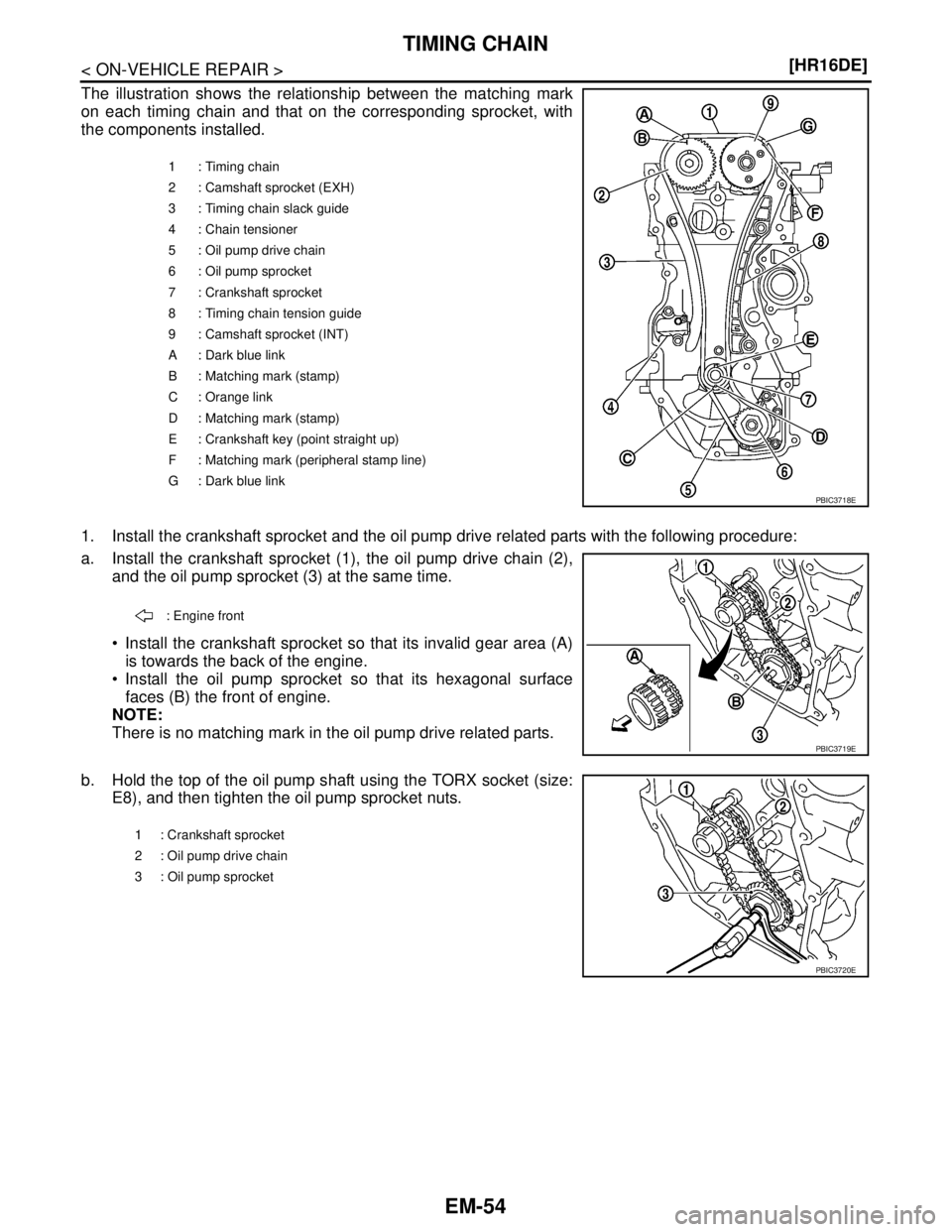
The illustration shows the relationship between the matching mark
on each timing chain and that on the corresponding sprocket, with
the components installed.
1. Install the crankshaft sprocket and the oil pump drive related parts with the following procedure:
a. Install the crankshaft sprocket (1), the oil pump drive chain (2),
and the oil pump sprocket (3) at the same time.
Install the crankshaft sprocket so that its invalid gear area (A)
is towards the back of the engine.
Install the oil pump sprocket so that its hexagonal surface
faces (B) the front of engine.
NOTE:
There is no matching mark in the oil pump drive related parts.
b. Hold the top of the oil pump shaft using the TORX socket (size:
E8), and then tighten the oil pump sprocket nuts.
1 : Timing chain
2 : Camshaft sprocket (EXH)
3 : Timing chain slack guide
4 : Chain tensioner
5 : Oil pump drive chain
6 : Oil pump sprocket
7 : Crankshaft sprocket
8 : Timing chain tension guide
9 : Camshaft sprocket (INT)
A : Dark blue link
B : Matching mark (stamp)
C : Orange link
D : Matching mark (stamp)
E : Crankshaft key (point straight up)
F : Matching mark (peripheral stamp line)
G : Dark blue link
PBIC3718E
: Engine front
PBIC3719E
1 : Crankshaft sprocket
2 : Oil pump drive chain
3 : Oil pump sprocket
PBIC3720E
Page 2905 of 5883
EM-258
< PREPARATION >[K9K]
PREPARATION
PREPARATION
PREPARATION
Special Service ToolsINFOID:0000000001381459
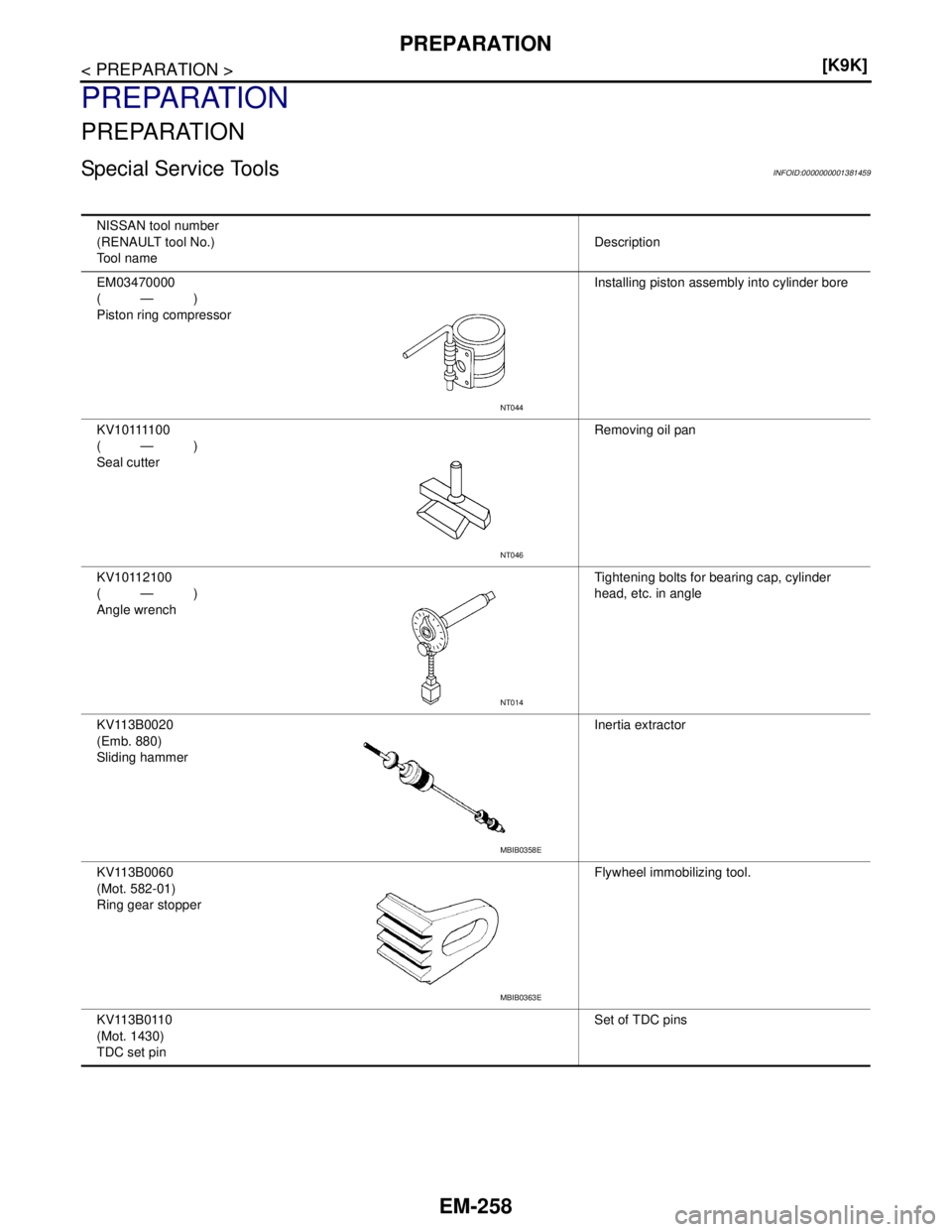
NISSAN tool number
(RENAULT tool No.)
Tool nameDescription
EM03470000
(—)
Piston ring compressorInstalling piston assembly into cylinder bore
K V 1 0 1111 0 0
(—)
Seal cutterRemoving oil pan
KV10112100
(—)
Angle wrenchTightening bolts for bearing cap, cylinder
head, etc. in angle
KV113B0020
(Emb. 880)
Sliding hammerInertia extractor
KV113B0060
(Mot. 582-01)
Ring gear stopperFlywheel immobilizing tool.
KV113B0110
(Mot. 1430)
TDC set pinSet of TDC pins
NT044
NT046
NT014
MBIB0358E
MBIB0363E
Page 2962 of 5883
CYLINDER BLOCK
EM-315
< DISASSEMBLY AND ASSEMBLY >[K9K]
C
D
E
F
G
H
I
J
K
L
MA
EM
N
P O
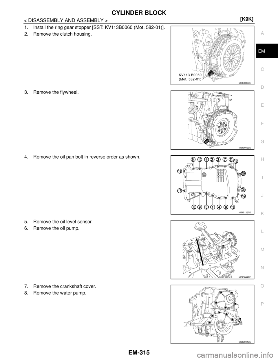
1. Install the ring gear stopper [SST: KV113B0060 (Mot. 582-01)].
2. Remove the clutch housing.
3. Remove the flywheel.
4. Remove the oil pan bolt in reverse order as shown.
5. Remove the oil level sensor.
6. Remove the oil pump.
7. Remove the crankshaft cover.
8. Remove the water pump.
MBIB0397E
MBIB0439E
MBIB1257E
MBIB0442E
MBIB0443E
Page 2977 of 5883
EM-330
< DISASSEMBLY AND ASSEMBLY >[K9K]
CYLINDER BLOCK
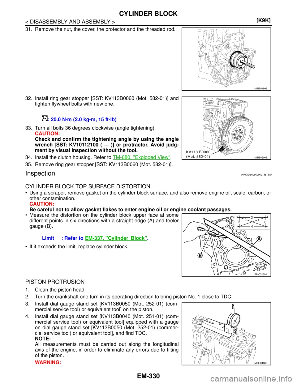
31. Remove the nut, the cover, the protector and the threaded rod.
32. Install ring gear stopper [SST: KV113B0060 (Mot. 582-01)] and
tighten flywheel bolts with new one.
33. Turn all bolts 36 degrees clockwise (angle tightening).
CAUTION:
Check and confirm the tightening angle by using the angle
wrench [SST: KV10112100 ( — )] or protractor. Avoid judg-
ment by visual inspection without the tool.
34. Install the clutch housing. Refer to TM-680, "
Exploded View".
35. Remove ring gear stopper [SST: KV113B0060 (Mot. 582-01)].
InspectionINFOID:0000000001381515
CYLINDER BLOCK TOP SURFACE DISTORTION
Using a scraper, remove gasket on the cylinder block surface, and also remove engine oil, scale, carbon, or
other contamination.
CAUTION:
Be careful not to allow gasket flakes to enter engine oil or engine coolant passages.
Measure the distortion on the cylinder block upper face at some
different points in six directions with a straight edge (A) and feeler
gauge (B).
If it exceeds the limit, replace cylinder block.
PISTON PROTRUSION
1. Clean the piston head.
2. Turn the crankshaft one turn in its operating direction to bring piston No. 1 close to TDC.
3. Install dial gauge stand set [KV113B0050 (Mot. 252-01) (com-
mercial service tool) or equivalent tool] on the piston.
4. Install dial gauge stand set [KV113B0040 (Mot. 251-01) (com-
mercial service tool) or equivalent tool] equipped with a gauge
on dial gauge stand set [KV113B0050 (Mot. 252-01) (commer-
cial service tool) or equivalent tool], and find TDC.
NOTE:
All measurements must be carried out along the longitudinal
axis of the engine, in order to eliminate any errors due to tilting
of the piston.
WARNING:
MBIB0499E
: 20.0 N·m (2.0 kg-m, 15 ft-lb)
MBIB0500E
Limit : Refer to EM-337, "CylinderBlock".
PBIC3250J
MBIB0480E