TM-203 NISSAN TIIDA 2007 Service Repair Manual
[x] Cancel search | Manufacturer: NISSAN, Model Year: 2007, Model line: TIIDA, Model: NISSAN TIIDA 2007Pages: 5883, PDF Size: 78.95 MB
Page 3731 of 5883
IP-16
< SERVICE INFORMATION >
INSTRUMENT PANEL ASSEMBLY
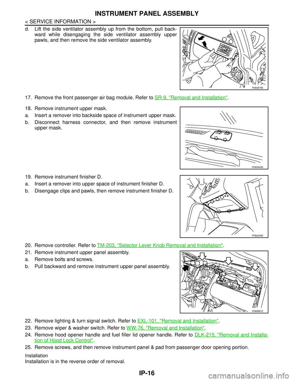
d. Lift the side ventilator assembly up from the bottom, pull back-
ward while disengaging the side ventilator assembly upper
pawls, and then remove the side ventilator assembly.
17. Remove the front passenger air bag module. Refer to SR-9, "
Removal and Installation".
18. Remove instrument upper mask.
a. Insert a remover into backside space of instrument upper mask.
b. Disconnect harness connector, and then remove instrument
upper mask.
19. Remove instrument finisher D.
a. Insert a remover into upper space of instrument finisher D.
b. Disengage clips and pawls, then remove instrument finisher D.
20. Remove controller. Refer to TM-203, "
Selector Lever Knob Removal and Installation".
21. Remove instrument upper panel assembly.
a. Remove bolts and screws.
b. Pull backward and remove instrument upper panel assembly.
22. Remove lighting & turn signal switch. Refer to EXL-101, "
Removal and Installation".
23. Remove wiper & washer switch. Refer to WW-76, "
Removal and Installation".
24. Remove hood opener handle and fuel filler lid opener handle. Refer to DLK-215, "
Removal and Installa-
tion of Hood Lock Control".
25. Remove screws, and then remove instrument panel & pad from passenger door opening portion.
Installation
Installation is in the reverse order of removal.
PIIB3979E
PIIB2445E
PIIB2446E
PIIB2881E
Page 5149 of 5883

SHIFT CONTROL SYSTEM
TM-203
< ON-VEHICLE REPAIR >[TYPE 1 (4AT: RE4F03B)]
C
E
F
G
H
I
J
K
L
MA
B
TM
N
O
P
When installing the control cable (1) to the control device assembly
(2), make sure that the control cable (1) is fully pressed in with the
ribbed surface (A) facing downward from the vehicle.
: Vehicle front
After installation is completed, adjust and check the A/T position.
Refer to TM-204, "
Adjustment of A/T Position" and TM-204,
"Checking of A/T Position".
Control Device Disassembly and AssemblyINFOID:0000000001731376
DISASSEMBLY
NOTE:
Refer to TM-200, "
Control Device Removal and Installation" to disassemble.
1. Remove selector lever knob from control device assembly. Refer to TM-203, "
Selector Lever Knob
Removal and Installation".
2. Remove position lamp from position indicator plate (1).
3. Insert a flat-bladed screwdriver to (A) (at 4 locations) as shown,
and bend each hook slightly to raise position indicator plate (1)
and remove from control device assembly (2).
4. Remove bracket from control device assembly (2).
5. Remove A/T device harness connector from control device
assembly (2).
6. Release tabs (A) on shift lock solenoid and park position switch
assembly from hooks (B) on control device assembly to shift
lock solenoid and park position switch assembly.
ASSEMBLY
Assemble in the reverse order of disassembly.
Selector Lever Knob Removal and InstallationINFOID:0000000001731377
REMOVAL
CAUTION:
Make sure that parking brake is applied before removal/installation.
SCIA6253E
SCIA6969E
SCIA6977E
Page 5152 of 5883

TM-206
< ON-VEHICLE REPAIR >[TYPE 1 (4AT: RE4F03B)]
KEY INTERLOCK CABLE
KEY INTERLOCK CABLE
Removal and InstallationINFOID:0000000001731380
COMPONENTS
REMOVAL
CAUTION:
Make sure that parking brake is applied before removal and installation.
1. Place the selector lever in the “N” position.
2. Remove the selector lever knob. Refer to TM-203, "
Selector Lever Knob Removal and Installation".
3. Remove the center console assembly. Refer to IP-11, "
Removal and Installation".
4. Slide the slider (A) toward the casing cap (B) while pressing tabs
(C) on the slider to separate the slider (A) from the adjust holder
(D).
5. Remove the casing cap (B) from the cable bracket on the control
device assembly.
6. Remove the key interlock cable from the key interlock rod (E).
1. Key interlock cable 2. Key cylinder 3. Control device assembly
A. Lock plate B. Holder C. Clip
D. Slider E. Key interlock rod F. Adjust holder
G. C a s i n g c a p
WCIA0621E
SCIA6975E
Page 5154 of 5883

TM-208
< ON-VEHICLE REPAIR >[TYPE 1 (4AT: RE4F03B)]
KEY INTERLOCK CABLE
8. Slide the slider (A) toward the key interlock rod (D) while press-
ing the pull lock (B) down to securely connect the adjust holder
(C) with the key interlock rod (D).
CAUTION:
Do not press tabs when holding slider (A).
Do not apply any side to side force to key interlock rod (D)
when sliding slider (A).
9. Secure the key interlock cable (1) with the clip (A).
10. Install steering column cover (upper and lower) and instrument
lower finisher. Refer to IP-11, "
Removal and Installation".
11. Install the center console assembly. Refer to IP-11, "
Removal
and Installation".
12. Install the selector lever knob. Refer to TM-203, "
Selector Lever
Knob Removal and Installation".
13. Check shift lock system. Refer to TM-31, "
System Description".
SCIA6978E
SCIA6973E