heater NISSAN TIIDA 2007 Service Repair Manual
[x] Cancel search | Manufacturer: NISSAN, Model Year: 2007, Model line: TIIDA, Model: NISSAN TIIDA 2007Pages: 5883, PDF Size: 78.95 MB
Page 1 of 5883

MODEL C11 SERIES
2007 NISSAN EUROPE S.A.S.
All rights reserved. No part of this Electronic Service Manual may be reproduced or stored in a retrieval system, or transmitted in any form,
or by any means, electronic, mechanical, photocopying, recording or otherwise, without the prior written permission of Nissan Europe
S.A.S., Paris, France.
A GENERAL INFORMATION
B ENGINE
D TRANSMISSION& DRIVELINE
E SUSPENSION F BRAKES
G STEERING H RESTRAINTS
I VENTILATION, HEATER & AIR CONDITIONER
J BODY INTERIOR
K BODY EXTERIOR, DOOR, ROOF & VEHICLE SECURITY
L DRIVER CONTROLS
M ELECTRICAL & POWER CONTROL
N DRIVER INFORMATION & MULTIMEDIA
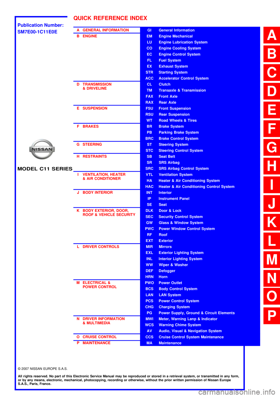
O CRUISE CONTROL P MAINTENANCEGI General Information
EM Engine Mechanical
LU Engine Lubrication System
CO Engine Cooling System
EC Engine Control System
FL Fuel System
EX Exhaust System
STR Starting System
ACC Accelerator Control System
CL Clutch
TM Transaxle & Transmission
FAX Front Axle
RAX Rear Axle
FSU Front Suspension
RSU Rear Suspension
WT Road Wheels & Tires
BR Brake System
PB Parking Brake System
BRC Brake Control System
ST Steering System
STC Steering Control System
SB Seat Belt
SR SRS Airbag
SRC SRS Airbag Control System
VTL Ventilation System
HA Heater & Air Conditioning System
HAC Heater & Air Conditioning Control System
INT Interior
IP Instrument Panel
SE Seat
DLK Door & Lock
SEC Security Control System
GW Glass & Window System
PWC Power Window Control System
RF Roof
EXT Exterior
MIR Mirrors
EXL Exterior Lighting System
INL Interior Lighting System
WW Wiper & Washer
DEF Defogger
HRN Horn
PWO Power Outlet
BCS Body Control System
LAN LAN System
PCS Power Control System
CHG Charging System
PG Power Supply, Ground & Circuit Elements
MWI Meter, Warning Lanp & Indicator
WCS Warning Chime System
AV Audio, Visual & Navigation System
CCS Cruise Control System Maintenance
MA Maintenance
QUICK REFERENCE INDEX
A
B
C
D
E
F
G
H
I
J
K
L
M
N
O
P
M
Publication Number:
SM7E00-1C11E0E
Page 137 of 5883

BCS-2
COMB SW : CONSULT-III Function (BCM -
COMB SW) .............................................................
24
IMMU .........................................................................24
IMMU : CONSULT-III Function (BCM - IMMU) .......24
BATTERY SAVER ....................................................25
BATTERY SAVER : CONSULT-III Function (BCM
- BATTERY SAVER) ..............................................
25
THEFT ALM ..............................................................26
THEFT ALM : CONSULT-III Function (BCM -
THEFT ALM) ..........................................................
26
SIGNAL BUFFER ......................................................26
SIGNAL BUFFER : CONSULT-III Function (BCM
- SIGNAL BUFFER) ................................................
26
PTC HEATER ............................................................26
PTC HEATER : CONSULT-III Function (BCM -
PTC HEATER) ........................................................
26
COMPONENT DIAGNOSIS ........................28
U1000 CAN COMM CIRCUIT ............................28
Description ..............................................................28
DTC Logic ...............................................................28
Diagnosis Procedure ..............................................28
U1010 CONTROL UNIT (CAN) .........................29
DTC Logic ...............................................................29
Diagnosis Procedure ..............................................29
Special Repair Requirement ...................................29
POWER SUPPLY AND GROUND CIRCUIT .....30
Diagnosis Procedure ..............................................30
COMBINATION SWITCH INPUT CIRCUIT .......31
Diagnosis Procedure ..............................................31
Special Repair Requirement ...................................32
COMBINATION SWITCH OUTPUT CIRCUIT ...33
Diagnosis Procedure ...............................................33
Special Repair Requirement ...................................33
COMBINATION SWITCH ..................................34
Description ..............................................................34
Diagnosis Procedure ...............................................34
ECU DIAGNOSIS .......................................35
BCM (BODY CONTROL MODULE) ..................35
Reference Value .....................................................35
Terminal Layout ......................................................38
Physical Values .......................................................39
Wiring Diagram .......................................................50
DTC Inspection Priority Chart ...............................53
DTC Index ..............................................................54
SYMPTOM DIAGNOSIS ............................55
COMBINATION SWITCH SYSTEM SYMP-
TOMS .................................................................
55
Symptom Table .......................................................55
PRECAUTION ............................................56
PRECAUTIONS .................................................56
Precaution for Supplemental Restraint System
(SRS) "AIR BAG" and "SEAT BELT PRE-TEN-
SIONER" .................................................................
56
ON-VEHICLE REPAIR ...............................57
BCM (BODY CONTROL MODULE) ..................57
Removal and Installation of BCM ............................57
Page 139 of 5883

BCS-4
< BASIC INSPECTION >
INSPECTION AND ADJUSTMENT
When replacing BCM, you must perform WRITE CONFIGURATION with CONSULT-III.
Complete the procedure of WRITE CONFIGURATION in order.
If you set incorrect WRITE CONFIGURATION, incidents will occur.
Configuration is different for each vehicle model. Confirm configuration of each vehicle model.
CONFIGURATION : Special Repair RequirementINFOID:0000000001451452
1. WRITING VEHICLE SPECIFICATION
Perform “WRITE CONFIGURATION” with CONSULT-III.
When writing saved data>>GO TO 2
When writing manually>>GO TO 3
2. PERFORM “WRITE CONFIGURATION - CONFIG FILE”
Perform “WRITE CONFIGURATION - Config file” with CONSULT-III.
>> WORK END
3. PERFORM “WRITE CONFIGURATION - MANUAL SELECTION”
For “WRITE CONFIGURATION - Manual selection”, using the following flow chart, identify the correct model
and configuration list.
Confirm and/or change setting value for each item according to the configuration list.
Depending on CONSULT-III software version being used, some or all of the write configuration items shown in
the following configuration lists may be displayed. If an item does not display on the CONSULT-III “WRITE
CONFIGURATION - Manual selection” screen, then it is an auto setting item and it cannot be manually set or
changed.
Gasoline engine models (RHD)
Gasoline engine models (LHD)
MANUAL SETTING ITEM
Items Setting value
HANDLE RHD
PTC HEATER WITHOUT
AUTO LIGHT WITH⇔WITHOUT
KEYLESS ENTRY WITH⇔WITHOUT
DTRL WITHOUT
THEFT ALARM WITH⇔WITHOUT
AUTO SETTING ITEM
RAIN SENSOR WITH or WITHOUT
H/L WSR SWTRG FR WSR SW
H/L_BULB H4 HALOGEN or DEFAULT
FR FOG LAMP WITH or WITHOUT
DONGLE WITH or WITHOUT
SUPER LOCK WITH
I-KEY WITH or WITHOUT
DOOR/L SPEED WITH
H/L BAT SAVER WITH
KEY WARNING MODE1
R LAMP LOGIC MODE2
Page 140 of 5883

BCS
INSPECTION AND ADJUSTMENT
BCS-5
< BASIC INSPECTION >
C
D
E
F
G
H
I
J
K
L B A
O
P N
Diesel engine models (RHD)
Diesel engine models (LHD)
MANUAL SETTING ITEM
Items Setting value
HANDLE LHD
PTC HEATER WITHOUT
AUTO LIGHT WITH⇔WITHOUT
KEYLESS ENTRY WITH⇔WITHOUT
DTRL WITH⇔WITHOUT
THEFT ALARM WITHOUT
AUTO SETTING ITEM
RAIN SENSOR WITH or WITHOUT
H/L WSR SWTRG FR WSR SW
H/L_BULB H4 HALOGEN or DEFAULT
FR FOG LAMP WITH or WITHOUT
DONGLE WITH or WITHOUT
SUPER LOCK WITHOUT
I-KEY WITH or WITHOUT
DOOR/L SPEED WITH
H/L BAT SAVER WITH
KEY WARNING MODE1
R LAMP LOGIC MODE2
MANUAL SETTING ITEM
Items Setting value
HANDLE RHD
PTC HEATER WITHOUT
AUTO LIGHT WITH⇔WITHOUT
KEYLESS ENTRY WITH⇔WITHOUT
DTRL WITHOUT
THEFT ALARM WITH⇔WITHOUT
AUTO SETTING ITEM
RAIN SENSOR WITH or WITHOUT
H/L WSR SWTRG FR WSR SW
H/L_BULB H4 HALOGEN or DEFAULT
FR FOG LAMP WITH or WITHOUT
DONGLE WITH or WITHOUT
SUPER LOCK WITH
I-KEY WITH or WITHOUT
DOOR/L SPEED WITH
H/L BAT SAVER WITH
KEY WARNING MODE1
R LAMP LOGIC MODE2
Page 141 of 5883

BCS-6
< BASIC INSPECTION >
INSPECTION AND ADJUSTMENT
>> WORK END
MANUAL SETTING ITEM
Items Setting value
HANDLE LHD
PTC HEATER 2 PTC
AUTO LIGHT WITH⇔WITHOUT
KEYLESS ENTRY WITH⇔WITHOUT
DTRL WITH⇔WITHOUT
THEFT ALARM WITHOUT
AUTO SETTING ITEM
RAIN SENSOR WITH or WITHOUT
H/L WSR SWTRG FR WSR SW
H/L_BULB H4 HALOGEN or DEFAULT
FR FOG LAMP WITH or WITHOUT
DONGLE WITH or WITHOUT
SUPER LOCK WITHOUT
I-KEY WITH or WITHOUT
DOOR/L SPEED WITH
H/L BAT SAVER WITH
KEY WARNING MODE1
R LAMP LOGIC MODE2
Page 143 of 5883

BCS-8
< FUNCTION DIAGNOSIS >
BODY CONTROL SYSTEM
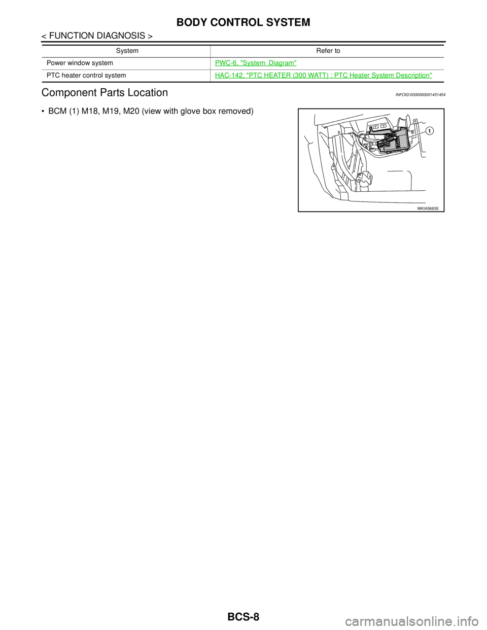
Component Parts Location
INFOID:0000000001451454
BCM (1) M18, M19, M20 (view with glove box removed)
Power window systemPWC-6, "SystemDiagram"
PTC heater control systemHAC-142, "PTC HEATER (300 WATT) : PTC Heater System Description"
System Refer to
WKIA5663E
Page 151 of 5883

BCS-16
< FUNCTION DIAGNOSIS >
DIAGNOSIS SYSTEM (BCM)
DIAGNOSIS SYSTEM (BCM)
COMMON ITEM
COMMON ITEM : CONSULT-III Function (BCM - COMMON ITEM)INFOID:0000000001451463
APPLICATION ITEM
CONSULT-III performs the following functions via CAN communication with BCM.
SYSTEM APPLICATION
BCM can perform the following functions for each system.
NOTE:
It can perform the diagnosis modes except the following for all sub system selection items.
1: With remote keyless entry system
2: With Intelligent Key
BCM
Diagnosis mode Function Description
WORK SUPPORT Changes the setting for each system function.
SELF-DIAG RESULTS Displays the diagnosis results judged by BCM. Refer to BCS-54, "
DTCIndex".
CAN DIAG SUPPORT MNTR Monitors the reception status of CAN communication viewed from BCM.
DATA MONITOR The BCM input/output signals are displayed.
ACTIVE TEST The signals used to activate each device are forcibly supplied from BCM.
ECU IDENTIFICATION The BCM part number is displayed.
CONFIGURATION Enables to read and save the vehicle specification.
Enables to write the vehicle specification when replacing BCM.
System Sub system selection itemDiagnosis mode
WORK SUPPORT DATA MONITOR ACTIVE TEST
BCM BCM×
Door lock DOOR LOCK×××
Rear window defogger REAR DEFOGGER××
Warning chime BUZZER××
Interior room lamp timer INT LAMP×××
Remote keyless entry system
1MULTI REMOTE ENT×××
Exterior lamp HEAD LAMP×××
Wiper and washer WIPER×××
Turn signal and hazard warning lamps FLASHER××
Air conditioner AIR CONDITONER×
Intelligent Key system
2INTELLIGENT KEY×
Combination switch COMB SW×
Immobilizer IMMU××
Interior room lamp battery saver BATTERY SAVER×××
Trunk open (sedan)/Back door open
(hatch back)DOOR LOCK××
Vehicle security system THEFT ALM×××
Signal buffer system SIGNAL BUFFER××
PTC heater system PTC HEATER××
Page 161 of 5883

BCS-26
< FUNCTION DIAGNOSIS >
DIAGNOSIS SYSTEM (BCM)
*: Each lamp switch is in ON position.
THEFT ALM
THEFT ALM : CONSULT-III Function (BCM - THEFT ALM)INFOID:0000000001451479
WORK SUPPORT
SIGNAL BUFFER
SIGNAL BUFFER : CONSULT-III Function (BCM - SIGNAL BUFFER)INFOID:0000000001451480
DATA MONITOR
ACTIVE TEST
PTC HEATER
PTC HEATER : CONSULT-III Function (BCM - PTC HEATER)INFOID:0000000001451481
DATA MONITOR
ACTIVE TEST
Work Item Description
SECURITY ALARM SETVehicle security function mode can be changed in this mode.
ON: Vehicle security function is ON.
OFF: Vehicle security function is OFF.
Monitor Item
[Unit]Description
OIL PRESS SW [ON/OFF] Displays the status of oil pressure switch received from IPDM E/R via CAN communication.
Test Item Operation Description
OIL PRESSURE SWOFF OFF
ONBCM transmits the oil pressure switch signal to the combination meter via CAN communica-
tion, which illuminates the oil pressure warning lamp in the combination meter.
Monitor Item
[Unit]Description
ELEC PWR CUT
[OFF/FREEZ/INHBT]Indicate [OFF/FREEZ/INHBT] condition of the PTC heater states.
FA N O N S I G
[On/Off]Displays [FAN (ON)/FAN (OFF)] status as judged from blower fan motor signal.
ENGINE STATUS
[STOP/STAL/RUN/CRA]Indicate [STOP/STALL/RUN/CRA] condition of the engine states.
ENG COOLNT T
[°C]The engine coolant temperature (determined by the signal voltage of the engine coolant tem-
perature sensor) is displayed.
BATTERY VOLT
[V]The power supply voltage of BCM is displayed.
ENGINE RPM
[rpm]Indicates the engine speed computed from the signal of the crankshaft position sensor.
OUTSIDE TEMP
[°C]The outside air temperature (determined by the signal voltage of the OAT sensor) is displayed.
Page 162 of 5883

BCS
DIAGNOSIS SYSTEM (BCM)
BCS-27
< FUNCTION DIAGNOSIS >
C
D
E
F
G
H
I
J
K
L B A
O
P N
Test Item Operation Description
PTC HEATEROFF
PTC 1
PTC 2
PTC 3This test is able to check PTC heater operation.
Page 182 of 5883

BCS
BCM (BODY CONTROL MODULE)
BCS-47
< ECU DIAGNOSIS >
C
D
E
F
G
H
I
J
K
L B A
O
P N
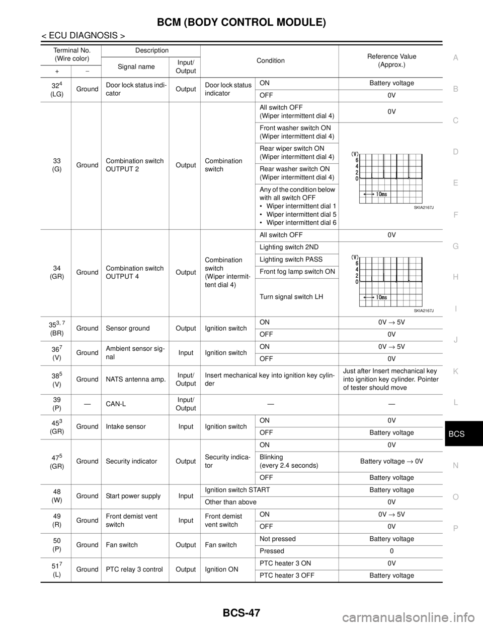
324
(LG)GroundDoor lock status indi-
catorOutputDoor lock status
indicatorON Battery voltage
OFF 0V
33
(G)GroundCombination switch
OUTPUT 2OutputCombination
switchAll switch OFF
(Wiper intermittent dial 4)0V
Front washer switch ON
(Wiper intermittent dial 4)
Rear wiper switch ON
(Wiper intermittent dial 4)
Rear washer switch ON
(Wiper intermittent dial 4)
Any of the condition below
with all switch OFF
Wiper intermittent dial 1
Wiper intermittent dial 5
Wiper intermittent dial 6
34
(GR)GroundCombination switch
OUTPUT 4OutputCombination
switch
(Wiper intermit-
tent dial 4)All switch OFF 0V
Lighting switch 2ND
Lighting switch PASS
Front fog lamp switch ON
Turn signal switch LH
35
3, 7
(BR)Ground Sensor ground Output Ignition switchON 0V → 5V
OFF 0V
36
7
(V)GroundAmbient sensor sig-
nalInput Ignition switchON 0V → 5V
OFF 0V
38
5
(V)Ground NATS antenna amp.Input/
OutputInsert mechanical key into ignition key cylin-
derJust after Insert mechanical key
into ignition key cylinder. Pointer
of tester should move
39
(P)—CAN-LInput/
Output——
45
3
(GR)Ground Intake sensor Input Ignition switchON 0V
OFF Battery voltage
47
5
(GR)Ground Security indicator OutputSecurity indica-
torON 0V
Blinking
(every 2.4 seconds)Battery voltage → 0V
OFF Battery voltage
48
(W)Ground Start power supply InputIgnition switch START Battery voltage
Other than above 0V
49
(R)GroundFront demist vent
switchInputFront demist
vent switchON 0V → 5V
OFF 0V
50
(P)Ground Fan switch Output Fan switchNot pressed Battery voltage
Pressed 0
51
7
(L)Ground PTC relay 3 control Output Ignition ONPTC heater 3 ON 0V
PTC heater 3 OFF Battery voltage Terminal No.
(Wire color)Description
ConditionReference Value
(Approx.)
Signal nameInput/
Output +−
SKIA2167J
SKIA2167J