NISSAN TIIDA 2008 Service Repair Manual
Manufacturer: NISSAN, Model Year: 2008, Model line: TIIDA, Model: NISSAN TIIDA 2008Pages: 2771, PDF Size: 60.61 MB
Page 1301 of 2771

DTC P0133 A/F SENSOR 1
EC-227
< SERVICE INFORMATION >
C
D
E
F
G
H
I
J
K
L
MA
EC
N
P O
• Lack of fuel
• Fuel injector
• Incorrect PCV hose connection
• PCV valve
• Mass air flow sensor
4. Turn ignition switch OFF and wait at least 10 seconds.
5. Start engine and keep the engine speed between 3,500 and 4,000 rpm for at least 1minute under no load.
6. Let engine idle for 1 minute.
7. Increase the engine speed up to 4,000 to 5,000 rpm and keep it for 10 seconds.
8. Fully release accelerator pedal and then let engine idle for about 1 minute.
9. Select Service $07 with GST.
If 1st trip DTC is detected, go to EC-229, "
Diagnosis Procedure".
Page 1302 of 2771

EC-228
< SERVICE INFORMATION >
DTC P0133 A/F SENSOR 1
Wiring Diagram
INFOID:0000000001702730
Specification data are reference values and are measured between each terminal and ground.
Pulse signal is measured by CONSULT-II.
CAUTION:
BBWA2631E
Page 1303 of 2771
DTC P0133 A/F SENSOR 1
EC-229
< SERVICE INFORMATION >
C
D
E
F
G
H
I
J
K
L
MA
EC
N
P O
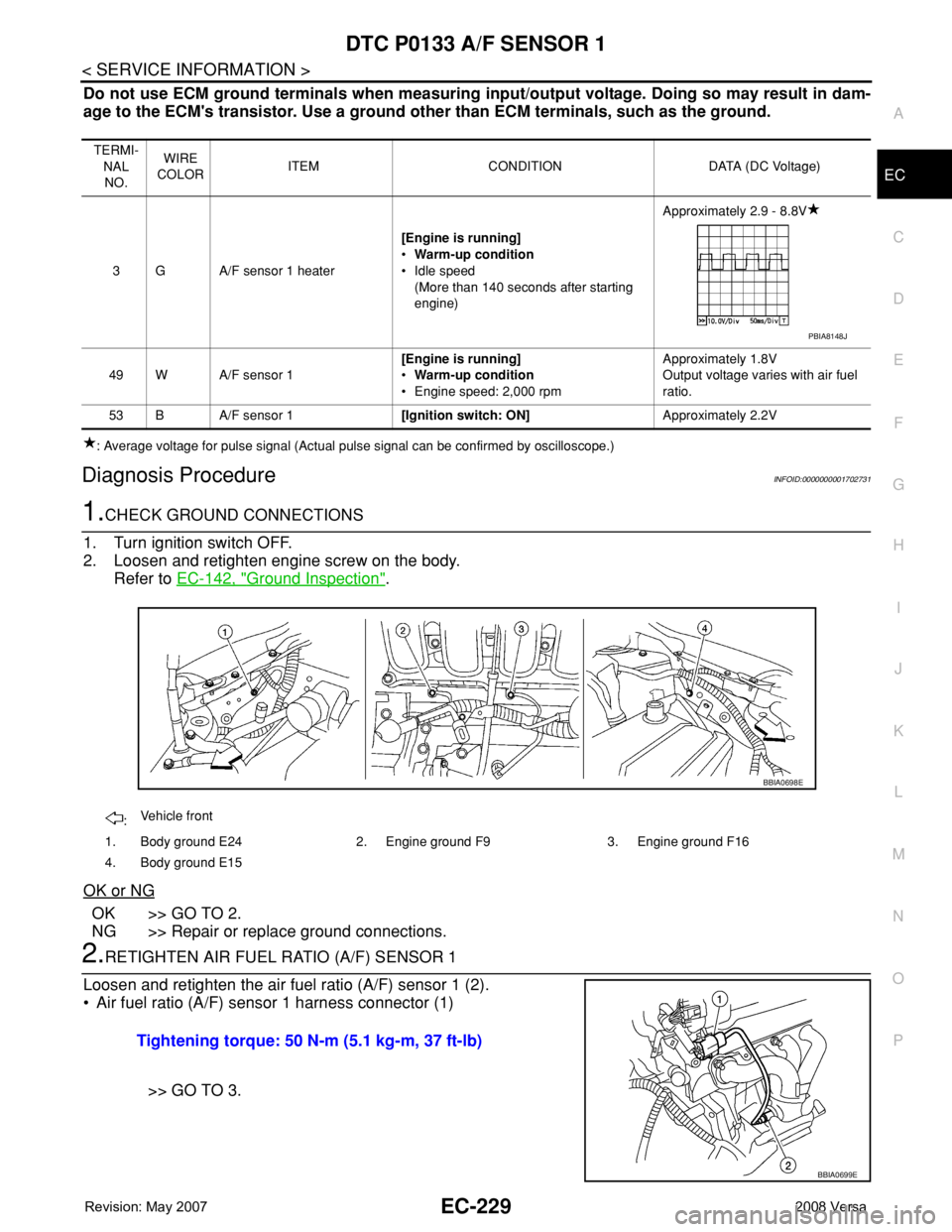
Do not use ECM ground terminals when measuring input/output voltage. Doing so may result in dam-
age to the ECM's transistor. Use a ground other than ECM terminals, such as the ground.
: Average voltage for pulse signal (Actual pulse signal can be confirmed by oscilloscope.)
Diagnosis ProcedureINFOID:0000000001702731
1.CHECK GROUND CONNECTIONS
1. Turn ignition switch OFF.
2. Loosen and retighten engine screw on the body.
Refer to EC-142, "
Ground Inspection".
OK or NG
OK >> GO TO 2.
NG >> Repair or replace ground connections.
2.RETIGHTEN AIR FUEL RATIO (A/F) SENSOR 1
Loosen and retighten the air fuel ratio (A/F) sensor 1 (2).
• Air fuel ratio (A/F) sensor 1 harness connector (1)
>> GO TO 3.
TERMI-
NAL
NO.WIRE
COLORITEM CONDITION DATA (DC Voltage)
3 G A/F sensor 1 heater[Engine is running]
•Warm-up condition
• Idle speed
(More than 140 seconds after starting
engine)Approximately 2.9 - 8.8V
49 W A/F sensor 1[Engine is running]
•Warm-up condition
• Engine speed: 2,000 rpmApproximately 1.8V
Output voltage varies with air fuel
ratio.
53 B A/F sensor 1[Ignition switch: ON]Approximately 2.2V
PBIA8148J
:Vehicle front
1. Body ground E24 2. Engine ground F9 3. Engine ground F16
4. Body ground E15
BBIA0698E
Tightening torque: 50 N-m (5.1 kg-m, 37 ft-lb)
BBIA0699E
Page 1304 of 2771
.
OK or NG
OK >")
EC-230
< SERVICE INFORMATION >
DTC P0133 A/F SENSOR 1
3.CHECK EXHAUST GAS LEAK
1. Start engine and run it at idle.
2. Listen for an exhaust gas leak before three way catalyst (manifold).
OK or NG
OK >> GO TO 4.
NG >> Repair or replace.
4.CHECK FOR INTAKE AIR LEAK
Listen for an intake air leak after the mass air flow sensor.
OK or NG
OK >> GO TO 5.
NG >> Repair or replace.
5.CLEAR THE SELF-LEARNING DATA
With CONSULT-II
1. Start engine and warm it up to normal operating temperature.
2. Select “SELF-LEARNING CONT” in “WORK SUPPORT” mode with CONSULT-II.
3. Clear the self-learning control coefficient by touching “CLEAR”
or “START”.
4. Run engine for at least 10 minutes at idle speed.
Is the 1st trip DTC P0171 or P0172 detected? Is it difficult to
start engine?
Without CONSULT-II
1. Start engine and warm it up to normal operating temperature.
2. Turn ignition switch OFF.
3. Disconnect mass air flow sensor (1) harness connector, and
restart and run engine for at least 5 seconds at idle speed.
4. Stop engine and reconnect mass air flow sensor harness con-
nector.
5. Make sure DTC P0102 is displayed.
6. Erase the DTC memory. Refer to EC-47, "
Emission-related
Diagnostic Information".
7. Make sure DTC P0000 is displayed.
8. Run engine for at least 10 minutes at idle speed.
Is the 1st trip DTC P0171 or P0172 detected? Is it difficult to
start engine?
Ye s o r N o
Yes >> Perform trouble diagnosis for DTC P0171, P0172. Refer to EC-257or EC-264.
No >> GO TO 6.
PBIB1216E
SEF215Z
BBIA0701E
Page 1305 of 2771
 SENSOR 1 POWER SUPPLY CIRCUIT
1. Turn ignition switch OFF.
2. Disconnect A/F sensor 1")
DTC P0133 A/F SENSOR 1
EC-231
< SERVICE INFORMATION >
C
D
E
F
G
H
I
J
K
L
MA
EC
N
P O
6.CHECK AIR FUEL RATIO (A/F) SENSOR 1 POWER SUPPLY CIRCUIT
1. Turn ignition switch OFF.
2. Disconnect A/F sensor 1 harness connector (1).
- Air fuel ratio (A/F) sensor (2)
3. Turn ignition switch ON.
4. Check voltage between A/F sensor 1 terminal 4 and ground with
CONSULT-II or tester.
OK or NG
OK >> GO TO 8.
NG >> GO TO 7.
7.DETECT MALFUNCTIONING PART
Check the following.
• Harness connectors E8, F8
• Harness for open or short between A/F sensor 1 and fuse
>> Repair or replace harness or connectors.
8.CHECK A/F SENSOR 1 INPUT SIGNAL CIRCUIT FOR OPEN AND SHORT
1. Turn ignition switch OFF.
2. Disconnect ECM harness connector.
3. Check harness continuity between the following terminals. Refer to Wiring Diagram.
4. Check harness continuity between ECM terminals 49, 53 or A/F sensor 1 terminals 1, 2 and ground.
Refer to Wiring Diagram.
5. Also check harness for short to power.
OK or NG
OK >> GO TO 9.
NG >> Repair open circuit or short to ground or short to power in harness or connectors.
9.CHECK AIR FUEL RATIO (A/F) SENSOR 1 HEATER
Refer to EC-154, "
Component Inspection".
OK or NG
BBIA0699E
Voltage: Battery voltage
PBIB3308E
A/F sensor 1 terminal ECM terminal
149
253
Continuity should exist.
Continuity should not exist.
Page 1306 of 2771

EC-232
< SERVICE INFORMATION >
DTC P0133 A/F SENSOR 1
OK >> GO TO 10.
NG >> GO TO 13.
10.CHECK MASS AIR FLOW SENSOR
Refer to EC-173, "
Component Inspection".
OK or NG
OK >> GO TO 11.
NG >> Replace mass air flow sensor.
11 .CHECK PCV VALVE
Refer to EC-43, "
Component Inspection".
OK or NG
OK >> GO TO 12.
NG >> Repair or replace PCV valve.
12.CHECK INTERMITTENT INCIDENT
Perform EC-136
.
OK or NG
OK >> GO TO 13.
NG >> Repair or replace.
13.REPLACE AIR FUEL RATIO (A/F) SENSOR 1
Replace air fuel ratio (A/F) sensor 1.
CAUTION:
• Discard any A/F sensor which has been dropped from a height of more than 0.5 m (19.7 in) onto a
hard surface such as a concrete floor; use a new one.
• Before installing new A/F sensor, clean exhaust system threads using Oxygen Sensor Thread
Cleaner tool J-43897-18 or J-43897-12 and approved anti-seize lubricant.
>>INSPECTION END
Removal and InstallationINFOID:0000000001702732
AIR FUEL RATIO SENSOR
Refer to EM-21.
Page 1307 of 2771

DTC P0137 HO2S2
EC-233
< SERVICE INFORMATION >
C
D
E
F
G
H
I
J
K
L
MA
EC
N
P O
DTC P0137 HO2S2
Component DescriptionINFOID:0000000001702733
The heated oxygen sensor 2, after three way catalyst (manifold),
monitors the oxygen level in the exhaust gas.
Even if switching characteristics of the air fuel ratio (A/F) sensor 1
are shifted, the air/fuel ratio is controlled to stoichiometric, by the sig-
nal from the heated oxygen sensor 2.
This sensor is made of ceramic zirconia. The zirconia generates volt-
age from approximately 1V in richer conditions to 0V in leaner condi-
tions.
Under normal conditions the heated oxygen sensor 2 is not used for
engine control operation.
CONSULT-II Reference Value in Data Monitor ModeINFOID:0000000001702734
Specification data are reference values.
On Board Diagnosis LogicINFOID:0000000001702735
The heated oxygen sensor 2 has a much longer switching time
between rich and lean than the air fuel ratio (A/F) sensor 1. The oxy-
gen storage capacity before the three way catalyst (manifold) causes
the longer switching time. To judge the malfunctions of heated oxy-
gen sensor 2, ECM monitors whether the maximum voltage of the
sensor is sufficiently high during the various driving condition such
as fuel-cut.
DTC Confirmation ProcedureINFOID:0000000001702736
NOTE:
If DTC confirmation Procedure has been previously conducted, always turn ignition switch OFF and wait at
least 10 seconds before conducting the next test.
WITH CONSULT-II
TESTING CONDITION:
For the best results, perform DTC WORK SUPPORT at a temperature of 0 to 30°C (32 to 86°F).
SEF327R
MONITOR ITEM CONDITION SPECIFICATION
HO2S2 (B1) • Revving engine from idle to 3,000 rpm quickly after the following
conditions are met.
- Engine: After warming up
- Keeping the engine speed between 3,500 and 4,000 rpm for 1
minute and at idle for 1 minute under no load0 - 0.3V ←→ Approx. 0.6 - 1.0V
HO2S2 MNTR (B1) LEAN ←→ RICH
SEF259VA
DTC No. Trouble diagnosis name DTC detecting condition Possible cause
P0137
0137Heated oxygen sensor 2 cir-
cuit low voltageThe maximum voltage from the sensor is not
reached to the specified voltage.• Harness or connectors
(Heated oxygen sensor 2 circuit open or
shorted.)
• Heated oxygen sensor 2
• Fuel pressure
• Fuel injector
• Intake air leaks
Page 1308 of 2771

EC-234
< SERVICE INFORMATION >
DTC P0137 HO2S2
1. Turn ignition switch ON and select “DATA MONITOR” mode with
CONSULT-II.
2. Start engine and warm it up to the normal operating tempera-
ture.
3. Turn ignition switch OFF and wait at least 10 seconds.
4. Start engine and keep the engine speed between 3,500 and
4,000 rpm for at least 1 minute under no load.
5. Let engine idle for 1 minute.
6. Make sure that “COOLAN TEMP/S” indicates more than 70°C
(158°F).
If not, warm up engine and go to next step when “COOLAN
TEMP/S” indication reaches to 70°C (158°F).
7. Open engine hood.
8. Select “HO2S2 (B1) P1147” of “HO2S2” in “DTC WORK SUPPORT” mode with CONSULT-II.
9. Start engine and following the instruction of CONSULT-II.
NOTE:
It will take at most 10 minutes until “COMPLETED” is displayed.
10. Make sure that “OK” is displayed after touching “SELF-DIAG RESULTS”.
If “NG” is displayed, refer to EC-236, "
Diagnosis Procedure".
If “CAN NOT BE DIAGNOSED” is displayed, perform the following.
a. Turn ignition switch OFF and leave the vehicle in a cool place (soak the vehicle).
b. Return to step 1.
Overall Function CheckINFOID:0000000001702737
Use this procedure to check the overall function of the heated oxygen sensor 2 circuit. During this check, a 1st
trip DTC might not be confirmed.
WITH GST
1. Start engine and warm it up to the normal operating temperature.
2. Turn ignition switch OFF and wait at least 10 seconds.
3. Start engine and keep the engine speed between 3,500 and 4,000 rpm for at least 1 minute under no load.
4. Let engine idle 1 minute.
5. Set voltmeter probes between ECM terminal 50 (HO2S2 signal) and ground.
6. Check the voltage when revving up to 4,000 rpm under no load
at least 10 times.
(Depress and release accelerator pedal as soon as possible.)
The voltage should be above 0.68V at least once during this
procedure.
If the voltage can be confirmed in step 6, step 7 is not nec-
essary.
7. Keep vehicle idling for 10 minutes, then check the voltage. Or
check the voltage when coasting from 80 km/h (50 MPH) in D
position with OD OFF (A/T), D position (CVT) or 3rd gear posi-
tion (M/T).
The voltage should be above 0.68V at least once during this
procedure.
SEF174Y
PBIB2373E
PBIB2996E
Page 1309 of 2771

DTC P0137 HO2S2
EC-235
< SERVICE INFORMATION >
C
D
E
F
G
H
I
J
K
L
MA
EC
N
P O
8. If NG, go to EC-236, "Diagnosis Procedure".
Wiring DiagramINFOID:0000000001702738
Specification data are reference values and are measured between each terminal and ground.
Pulse signal is measured by CONSULT-II.
CAUTION:
BBWA2629E
Page 1310 of 2771

EC-236
< SERVICE INFORMATION >
DTC P0137 HO2S2
Do not use ECM ground terminals when measuring input/output voltage. Doing so may result in dam-
age to the ECM's transistor. Use a ground other than ECM terminals, such as the ground.
: Average voltage for pulse signal (Actual pulse signal can be confirmed by oscilloscope.)
Diagnosis ProcedureINFOID:0000000001702739
1.CHECK GROUND CONNECTIONS
1. Turn ignition switch OFF.
2. Loosen and retighten ground screw on the body.
Refer to EC-142, "
Ground Inspection".
OK or NG
OK >> GO TO 2.
NG >> Repair or replace ground connections.
2.CLEAR THE SELF-LEARNING DATA
With CONSULT-II
TERMI-
NAL
NO.WIRE
COLORITEM CONDITION DATA (DC Voltage)
5GHeated oxygen sensor 2
heater[Engine is running]
• Engine speed: Below 3,600 rpm after the
following conditions are met.
- Engine: After warming up
- Keeping the engine speed between
3,500 and 4,000 rpm for 1 minute and at
idle for 1 minute under no load.Approximately 10V
[Ignition switch: ON]
• Engine stopped
[Engine is running]
• Engine speed: Above 3,600 rpm.BATTERY VOLTAGE
(11 - 14V)
50 W Heated oxygen sensor 2[Engine is running]
• Revving engine from idle to 3,000 rpm
quickly after the following conditions are
met.
- Engine: After warming up
- Keeping the engine speed between
3,500 and 4,000 rpm for 1 minute and at
idle for 1 minute under no load.0 - Approximately 1.0V
59 OSensor ground
(Heated oxygen sensor 2)[Engine is running]
•Warm-up condition
• Idle speedApproximately 0V
PBIA8148J
:Vehicle front
1. Body ground E24 2. Engine ground F9 3. Engine ground F16
4. Body ground E15
BBIA0698E