NISSAN TIIDA 2008 Service Repair Manual
Manufacturer: NISSAN, Model Year: 2008, Model line: TIIDA, Model: NISSAN TIIDA 2008Pages: 2771, PDF Size: 60.61 MB
Page 1411 of 2771
DTC P0444, P0445 EVAP CANISTER PURGE VOLUME CONTROL SOLENOID
VALVE
EC-337
< SERVICE INFORMATION >
C
D
E
F
G
H
I
J
K
L
MA
EC
N
P O
>>INSPECTION END
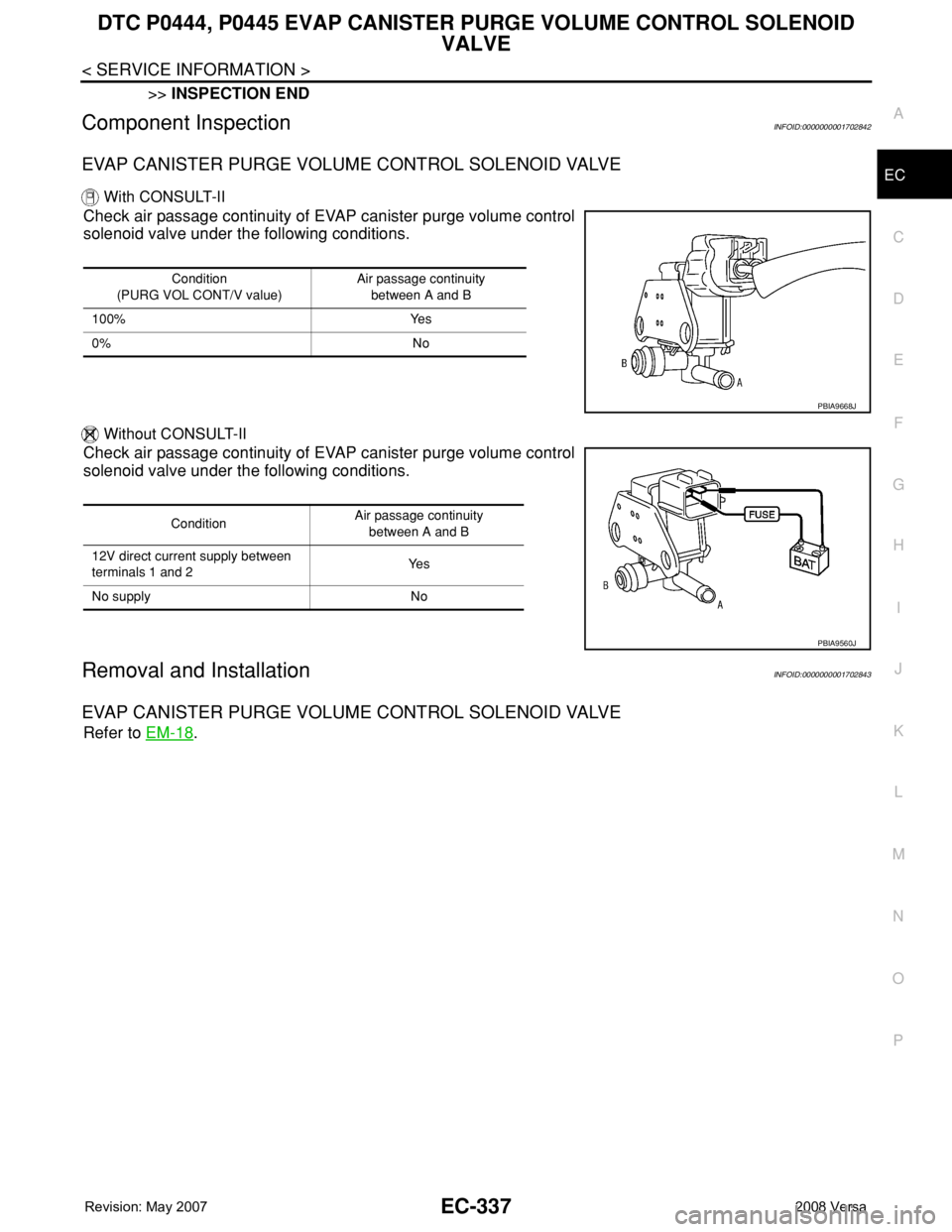
Component InspectionINFOID:0000000001702842
EVAP CANISTER PURGE VOLUME CONTROL SOLENOID VALVE
With CONSULT-II
Check air passage continuity of EVAP canister purge volume control
solenoid valve under the following conditions.
Without CONSULT-II
Check air passage continuity of EVAP canister purge volume control
solenoid valve under the following conditions.
Removal and InstallationINFOID:0000000001702843
EVAP CANISTER PURGE VOLUME CONTROL SOLENOID VALVE
Refer to EM-18.
Condition
(PURG VOL CONT/V value)Air passage continuity
between A and B
100% Yes
0% No
PBIA9668J
ConditionAir passage continuity
between A and B
12V direct current supply between
terminals 1 and 2Ye s
No supply No
PBIA9560J
Page 1412 of 2771
EC-338
< SERVICE INFORMATION >
DTC P0447 EVAP CANISTER VENT CONTROL VALVE
DTC P0447 EVAP CANISTER VENT CONTROL VALVE
Component DescriptionINFOID:0000000001702844
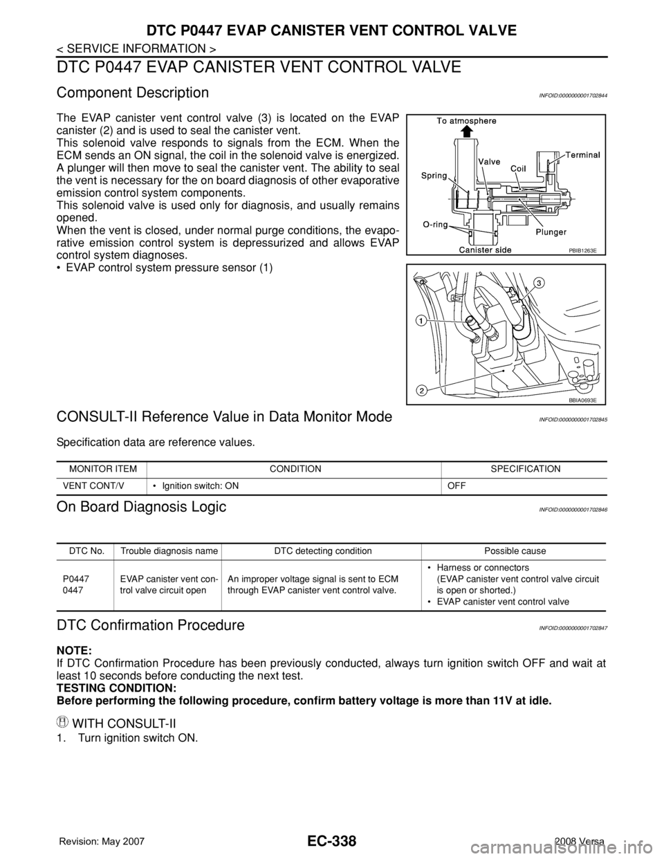
The EVAP canister vent control valve (3) is located on the EVAP
canister (2) and is used to seal the canister vent.
This solenoid valve responds to signals from the ECM. When the
ECM sends an ON signal, the coil in the solenoid valve is energized.
A plunger will then move to seal the canister vent. The ability to seal
the vent is necessary for the on board diagnosis of other evaporative
emission control system components.
This solenoid valve is used only for diagnosis, and usually remains
opened.
When the vent is closed, under normal purge conditions, the evapo-
rative emission control system is depressurized and allows EVAP
control system diagnoses.
• EVAP control system pressure sensor (1)
CONSULT-II Reference Value in Data Monitor ModeINFOID:0000000001702845
Specification data are reference values.
On Board Diagnosis LogicINFOID:0000000001702846
DTC Confirmation ProcedureINFOID:0000000001702847
NOTE:
If DTC Confirmation Procedure has been previously conducted, always turn ignition switch OFF and wait at
least 10 seconds before conducting the next test.
TESTING CONDITION:
Before performing the following procedure, confirm battery voltage is more than 11V at idle.
WITH CONSULT-II
1. Turn ignition switch ON.
PBIB1263E
BBIA0693E
MONITOR ITEM CONDITION SPECIFICATION
VENT CONT/V • Ignition switch: ON OFF
DTC No. Trouble diagnosis name DTC detecting condition Possible cause
P0447
0447EVAP canister vent con-
trol valve circuit openAn improper voltage signal is sent to ECM
through EVAP canister vent control valve.• Harness or connectors
(EVAP canister vent control valve circuit
is open or shorted.)
• EVAP canister vent control valve
Page 1413 of 2771

DTC P0447 EVAP CANISTER VENT CONTROL VALVE
EC-339
< SERVICE INFORMATION >
C
D
E
F
G
H
I
J
K
L
MA
EC
N
P O
2. Select “DATA MONITOR” mode with CONSULT-II.
3. Start engine and wait at least 8 seconds.
4. If 1st trip DTC is detected, go to EC-341, "
Diagnosis Procedure".
WITH GST
Follow the procedure “WITH CONSULT-II” above.
SEF058Y
Page 1414 of 2771
EC-340
< SERVICE INFORMATION >
DTC P0447 EVAP CANISTER VENT CONTROL VALVE
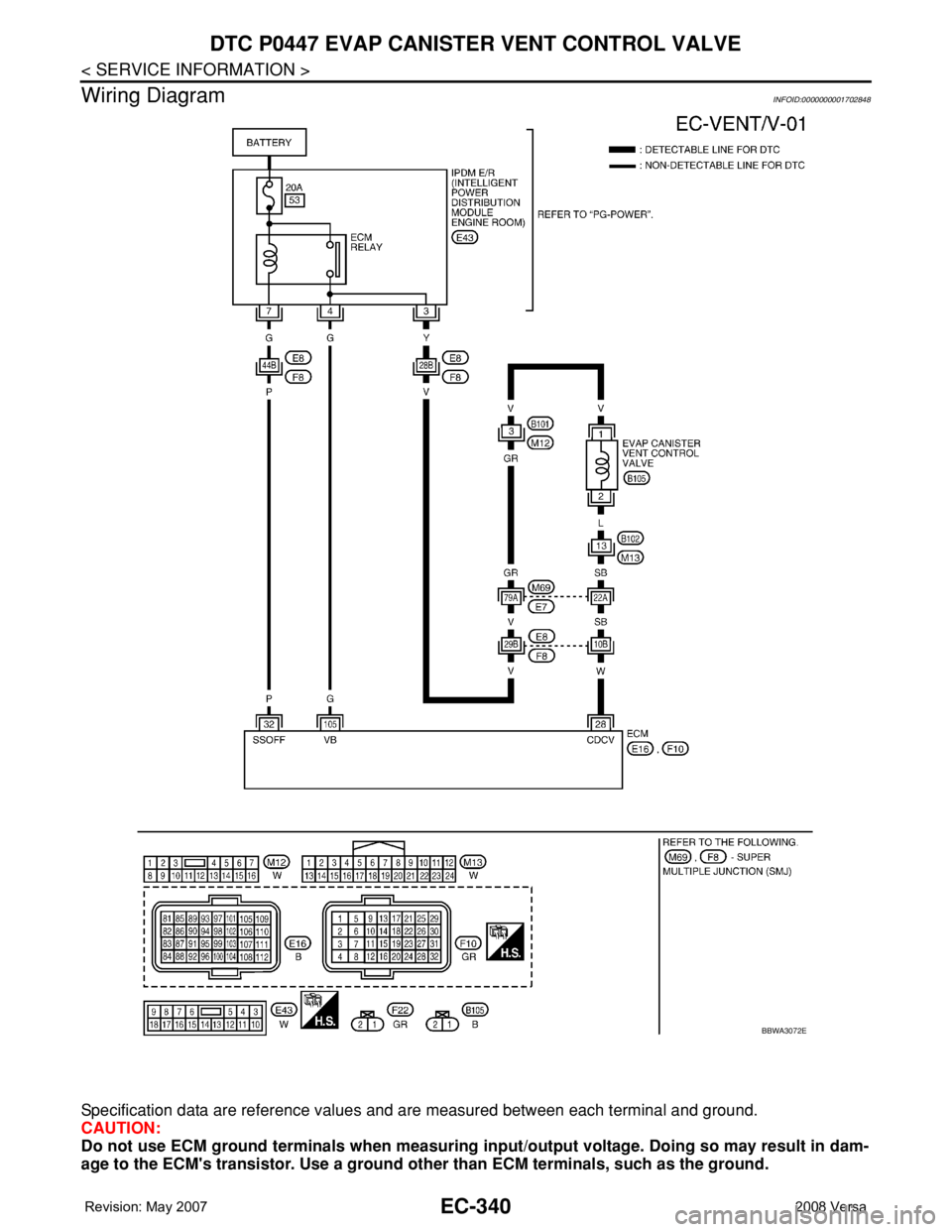
Wiring Diagram
INFOID:0000000001702848
Specification data are reference values and are measured between each terminal and ground.
CAUTION:
Do not use ECM ground terminals when measuring input/output voltage. Doing so may result in dam-
age to the ECM's transistor. Use a ground other than ECM terminals, such as the ground.
BBWA3072E
Page 1415 of 2771
DTC P0447 EVAP CANISTER VENT CONTROL VALVE
EC-341
< SERVICE INFORMATION >
C
D
E
F
G
H
I
J
K
L
MA
EC
N
P O
Diagnosis ProcedureINFOID:0000000001702849
1.INSPECTION START
1. Do you have CONSULT-II?
Ye s o r N o
Yes >> GO TO 2.
No >> GO TO 3.
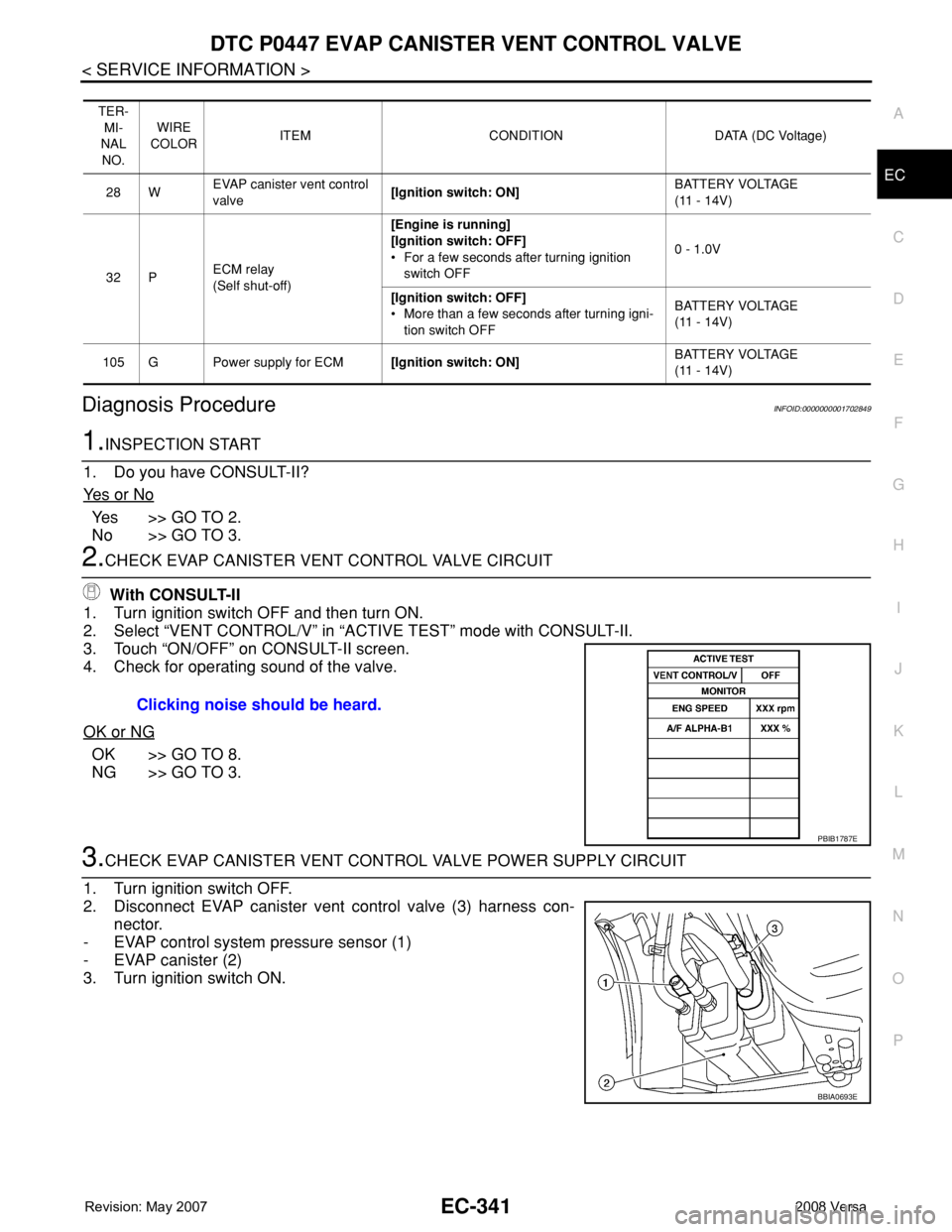
2.CHECK EVAP CANISTER VENT CONTROL VALVE CIRCUIT
With CONSULT-II
1. Turn ignition switch OFF and then turn ON.
2. Select “VENT CONTROL/V” in “ACTIVE TEST” mode with CONSULT-II.
3. Touch “ON/OFF” on CONSULT-II screen.
4. Check for operating sound of the valve.
OK or NG
OK >> GO TO 8.
NG >> GO TO 3.
3.CHECK EVAP CANISTER VENT CONTROL VALVE POWER SUPPLY CIRCUIT
1. Turn ignition switch OFF.
2. Disconnect EVAP canister vent control valve (3) harness con-
nector.
- EVAP control system pressure sensor (1)
- EVAP canister (2)
3. Turn ignition switch ON.
TER-
MI-
NAL
NO.WIRE
COLORITEM CONDITION DATA (DC Voltage)
28 WEVAP canister vent control
valve[Ignition switch: ON]BATTERY VOLTAGE
(11 - 14V)
32 PECM relay
(Self shut-off)[Engine is running]
[Ignition switch: OFF]
• For a few seconds after turning ignition
switch OFF0 - 1.0V
[Ignition switch: OFF]
• More than a few seconds after turning igni-
tion switch OFFBATTERY VOLTAGE
(11 - 14V)
105 G Power supply for ECM[Ignition switch: ON]BATTERY VOLTAGE
(11 - 14V)
Clicking noise should be heard.
PBIB1787E
BBIA0693E
Page 1416 of 2771
EC-342
< SERVICE INFORMATION >
DTC P0447 EVAP CANISTER VENT CONTROL VALVE
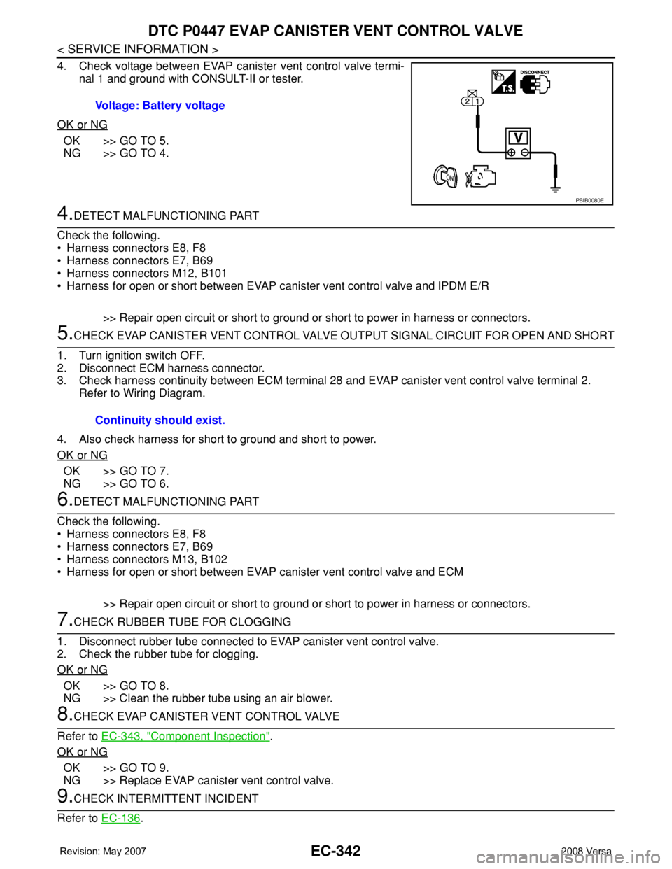
4. Check voltage between EVAP canister vent control valve termi-
nal 1 and ground with CONSULT-II or tester.
OK or NG
OK >> GO TO 5.
NG >> GO TO 4.
4.DETECT MALFUNCTIONING PART
Check the following.
• Harness connectors E8, F8
• Harness connectors E7, B69
• Harness connectors M12, B101
• Harness for open or short between EVAP canister vent control valve and IPDM E/R
>> Repair open circuit or short to ground or short to power in harness or connectors.
5.CHECK EVAP CANISTER VENT CONTROL VALVE OUTPUT SIGNAL CIRCUIT FOR OPEN AND SHORT
1. Turn ignition switch OFF.
2. Disconnect ECM harness connector.
3. Check harness continuity between ECM terminal 28 and EVAP canister vent control valve terminal 2.
Refer to Wiring Diagram.
4. Also check harness for short to ground and short to power.
OK or NG
OK >> GO TO 7.
NG >> GO TO 6.
6.DETECT MALFUNCTIONING PART
Check the following.
• Harness connectors E8, F8
• Harness connectors E7, B69
• Harness connectors M13, B102
• Harness for open or short between EVAP canister vent control valve and ECM
>> Repair open circuit or short to ground or short to power in harness or connectors.
7.CHECK RUBBER TUBE FOR CLOGGING
1. Disconnect rubber tube connected to EVAP canister vent control valve.
2. Check the rubber tube for clogging.
OK or NG
OK >> GO TO 8.
NG >> Clean the rubber tube using an air blower.
8.CHECK EVAP CANISTER VENT CONTROL VALVE
Refer to EC-343, "
Component Inspection".
OK or NG
OK >> GO TO 9.
NG >> Replace EVAP canister vent control valve.
9.CHECK INTERMITTENT INCIDENT
Refer to EC-136
. Voltage: Battery voltage
PBIB0080E
Continuity should exist.
Page 1417 of 2771
DTC P0447 EVAP CANISTER VENT CONTROL VALVE
EC-343
< SERVICE INFORMATION >
C
D
E
F
G
H
I
J
K
L
MA
EC
N
P O
>>INSPECTION END
Component InspectionINFOID:0000000001702850
EVAP CANISTER VENT CONTROL VALVE
With CONSULT-II
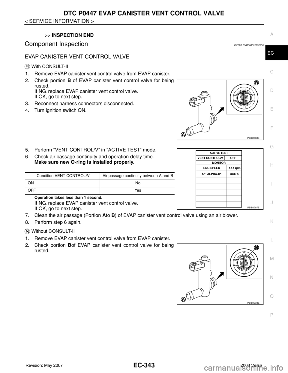
1. Remove EVAP canister vent control valve from EVAP canister.
2. Check portion B of EVAP canister vent control valve for being
rusted.
If NG, replace EVAP canister vent control valve.
If OK, go to next step.
3. Reconnect harness connectors disconnected.
4. Turn ignition switch ON.
5. Perform “VENT CONTROL/V” in “ACTIVE TEST” mode.
6. Check air passage continuity and operation delay time.
Make sure new O-ring is installed properly.
Operation takes less than 1 second.
If NG, replace EVAP canister vent control valve.
If OK, go to next step.
7. Clean the air passage (Portion Ato B) of EVAP canister vent control valve using an air blower.
8. Perform step 6 again.
Without CONSULT-II
1. Remove EVAP canister vent control valve from EVAP canister.
2. Check portion Bof EVAP canister vent control valve for being
rusted.
PBIB1033E
Condition VENT CONTROL/V Air passage continuity between A and B
ON No
OFF Yes
PBIB1787E
PBIB1033E
Page 1418 of 2771

EC-344
< SERVICE INFORMATION >
DTC P0447 EVAP CANISTER VENT CONTROL VALVE
3. Check air passage continuity and operation delay time under the
following conditions.
Make sure new O-ring is installed properly.
Operation takes less than 1 second.
If NG, replace EVAP canister vent control valve.
If OK, go to next step.
4. Clean the air passage (Portion A to B) of EVAP canister vent control valve using an air blower.
5. Perform step 3 again.
Condition Air passage continuity between A and B
12V direct current supply between
terminals 1 and 2No
OFF Yes
PBIB1034E
Page 1419 of 2771
DTC P0448 EVAP CANISTER VENT CONTROL VALVE
EC-345
< SERVICE INFORMATION >
C
D
E
F
G
H
I
J
K
L
MA
EC
N
P O
DTC P0448 EVAP CANISTER VENT CONTROL VALVE
Component DescriptionINFOID:0000000001702851
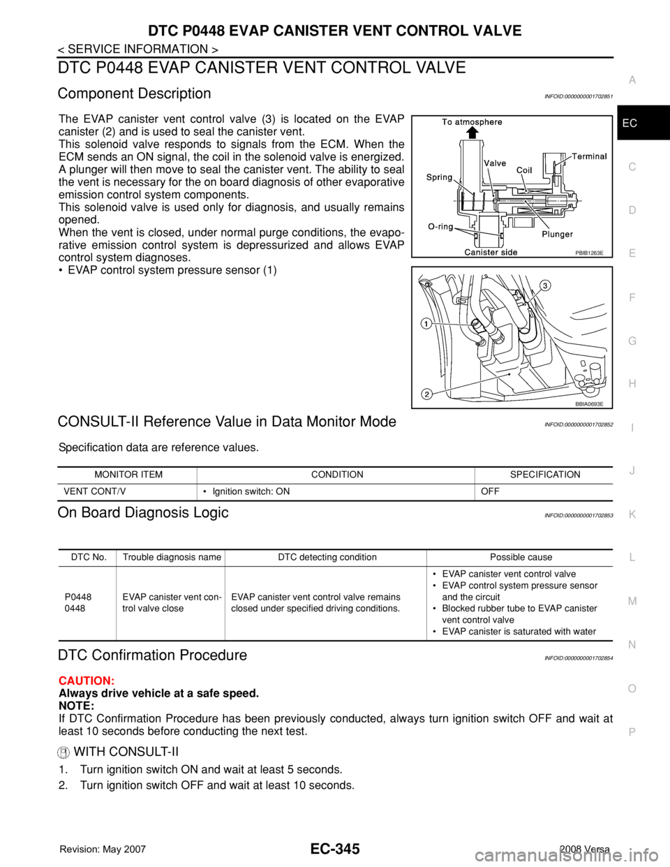
The EVAP canister vent control valve (3) is located on the EVAP
canister (2) and is used to seal the canister vent.
This solenoid valve responds to signals from the ECM. When the
ECM sends an ON signal, the coil in the solenoid valve is energized.
A plunger will then move to seal the canister vent. The ability to seal
the vent is necessary for the on board diagnosis of other evaporative
emission control system components.
This solenoid valve is used only for diagnosis, and usually remains
opened.
When the vent is closed, under normal purge conditions, the evapo-
rative emission control system is depressurized and allows EVAP
control system diagnoses.
• EVAP control system pressure sensor (1)
CONSULT-II Reference Value in Data Monitor ModeINFOID:0000000001702852
Specification data are reference values.
On Board Diagnosis LogicINFOID:0000000001702853
DTC Confirmation ProcedureINFOID:0000000001702854
CAUTION:
Always drive vehicle at a safe speed.
NOTE:
If DTC Confirmation Procedure has been previously conducted, always turn ignition switch OFF and wait at
least 10 seconds before conducting the next test.
WITH CONSULT-II
1. Turn ignition switch ON and wait at least 5 seconds.
2. Turn ignition switch OFF and wait at least 10 seconds.
PBIB1263E
BBIA0693E
MONITOR ITEM CONDITION SPECIFICATION
VENT CONT/V • Ignition switch: ON OFF
DTC No. Trouble diagnosis name DTC detecting condition Possible cause
P0448
0448EVAP canister vent con-
trol valve closeEVAP canister vent control valve remains
closed under specified driving conditions.• EVAP canister vent control valve
• EVAP control system pressure sensor
and the circuit
• Blocked rubber tube to EVAP canister
vent control valve
• EVAP canister is saturated with water
Page 1420 of 2771
EC-346
< SERVICE INFORMATION >
DTC P0448 EVAP CANISTER VENT CONTROL VALVE
3. Turn ignition switch ON and select “DATA MONITOR” mode with
CONSULT-II.
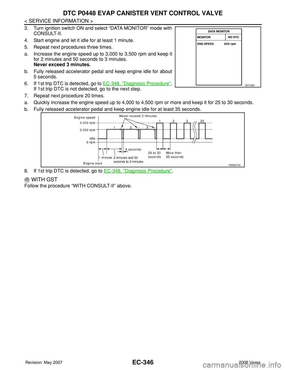
4. Start engine and let it idle for at least 1 minute.
5. Repeat next procedures three times.
a. Increase the engine speed up to 3,000 to 3,500 rpm and keep it
for 2 minutes and 50 seconds to 3 minutes.
Never exceed 3 minutes.
b. Fully released accelerator pedal and keep engine idle for about
5 seconds.
6. If 1st trip DTC is detected, go to EC-348, "
Diagnosis Procedure".
If 1st trip DTC is not detected, go to the next step.
7. Repeat next procedure 20 times.
a. Quickly increase the engine speed up to 4,000 to 4,500 rpm or more and keep it for 25 to 30 seconds.
b. Fully released accelerator pedal and keep engine idle for at least 35 seconds.
8. If 1st trip DTC is detected, go to EC-348, "
Diagnosis Procedure".
WITH GST
Follow the procedure “WITH CONSULT-II” above.
SEF058Y
PBIB0972E