NISSAN TIIDA 2008 Service Repair Manual
TIIDA 2008
NISSAN
NISSAN
https://www.carmanualsonline.info/img/5/57399/w960_57399-0.png
NISSAN TIIDA 2008 Service Repair Manual
Trending: transmission fluid, Eps, Pressure, meter, fuse, Dashboard, engine coolant
Page 261 of 2771
DISASSEMBLY
AT-249
< SERVICE INFORMATION >
D
E
F
G
H
I
J
K
L
MA
B
AT
N
O
P
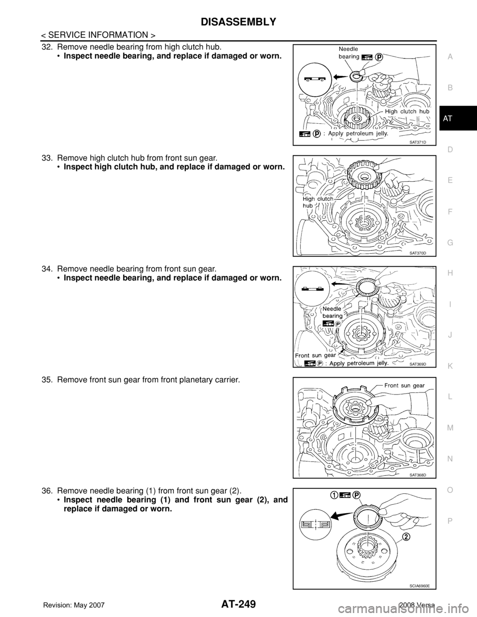
32. Remove needle bearing from high clutch hub.
•Inspect needle bearing, and replace if damaged or worn.
33. Remove high clutch hub from front sun gear.
•Inspect high clutch hub, and replace if damaged or worn.
34. Remove needle bearing from front sun gear.
•Inspect needle bearing, and replace if damaged or worn.
35. Remove front sun gear from front planetary carrier.
36. Remove needle bearing (1) from front sun gear (2).
•Inspect needle bearing (1) and front sun gear (2), and
replace if damaged or worn.
SAT371D
SAT370D
SAT369D
SAT368D
SCIA6960E
Page 262 of 2771
AT-250
< SERVICE INFORMATION >
DISASSEMBLY
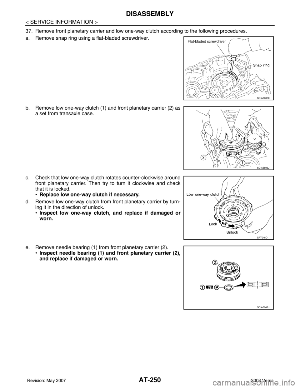
37. Remove front planetary carrier and low one-way clutch according to the following procedures.
a. Remove snap ring using a flat-bladed screwdriver.
b. Remove low one-way clutch (1) and front planetary carrier (2) as
a set from transaxle case.
c. Check that low one-way clutch rotates counter-clockwise around
front planetary carrier. Then try to turn it clockwise and check
that it is locked.
•Replace low one-way clutch if necessary.
d. Remove low one-way clutch from front planetary carrier by turn-
ing it in the direction of unlock.
•Inspect low one-way clutch, and replace if damaged or
worn.
e. Remove needle bearing (1) from front planetary carrier (2).
•Inspect needle bearing (1) and front planetary carrier (2),
and replace if damaged or worn.
SCIA3633E
SCIA5896J
SAT048D
SCIA6047J
Page 263 of 2771
DISASSEMBLY
AT-251
< SERVICE INFORMATION >
D
E
F
G
H
I
J
K
L
MA
B
AT
N
O
P
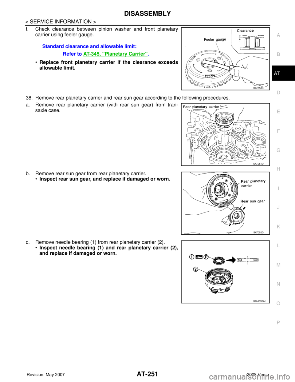
f. Check clearance between pinion washer and front planetary
carrier using feeler gauge.
•Replace front planetary carrier if the clearance exceeds
allowable limit.
38. Remove rear planetary carrier and rear sun gear according to the following procedures.
a. Remove rear planetary carrier (with rear sun gear) from tran-
saxle case.
b. Remove rear sun gear from rear planetary carrier.
•Inspect rear sun gear, and replace if damaged or worn.
c. Remove needle bearing (1) from rear planetary carrier (2).
•Inspect needle bearing (1) and rear planetary carrier (2),
and replace if damaged or worn. Standard clearance and allowable limit:
Refer to AT-345, "
Planetary Carrier".
SAT050D
SAT051D
SAT052D
SCIA5927J
Page 264 of 2771
AT-252
< SERVICE INFORMATION >
DISASSEMBLY
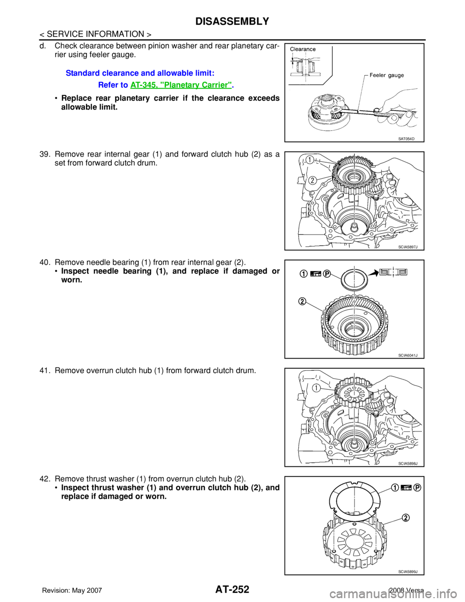
d. Check clearance between pinion washer and rear planetary car-
rier using feeler gauge.
•Replace rear planetary carrier if the clearance exceeds
allowable limit.
39. Remove rear internal gear (1) and forward clutch hub (2) as a
set from forward clutch drum.
40. Remove needle bearing (1) from rear internal gear (2).
•Inspect needle bearing (1), and replace if damaged or
worn.
41. Remove overrun clutch hub (1) from forward clutch drum.
42. Remove thrust washer (1) from overrun clutch hub (2).
•Inspect thrust washer (1) and overrun clutch hub (2), and
replace if damaged or worn.Standard clearance and allowable limit:
Refer to AT-345, "
Planetary Carrier".
SAT054D
SCIA5897J
SCIA6041J
SCIA5898J
SCIA5899J
Page 265 of 2771
DISASSEMBLY
AT-253
< SERVICE INFORMATION >
D
E
F
G
H
I
J
K
L
MA
B
AT
N
O
P
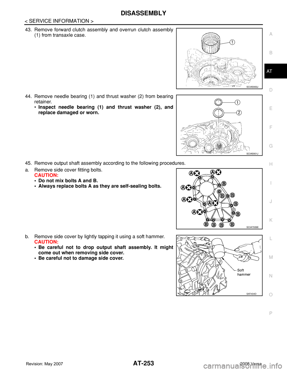
43. Remove forward clutch assembly and overrun clutch assembly
(1) from transaxle case.
44. Remove needle bearing (1) and thrust washer (2) from bearing
retainer.
•Inspect needle bearing (1) and thrust washer (2), and
replace damaged or worn.
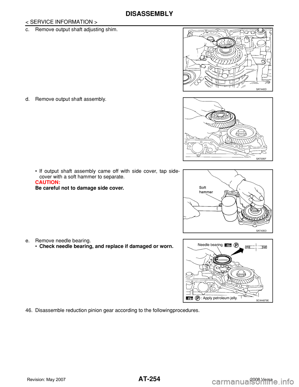
45. Remove output shaft assembly according to the following procedures.
a. Remove side cover fitting bolts.
CAUTION:
• Do not mix bolts A and B.
• Always replace bolts A as they are self-sealing bolts.
b. Remove side cover by lightly tapping it using a soft hammer.
CAUTION:
• Be careful not to drop output shaft assembly. It might
come out when removing side cover.
• Be careful not to damage side cover.
SCIA5900J
SCIA5901J
SCIA7939E
SAT434D
Page 266 of 2771
AT-254
< SERVICE INFORMATION >
DISASSEMBLY
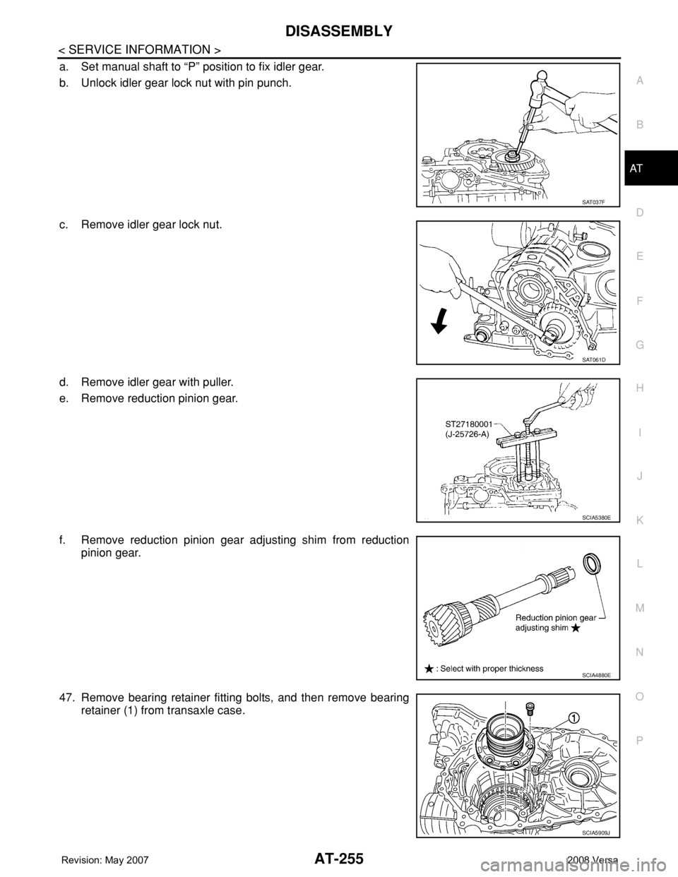
c. Remove output shaft adjusting shim.
d. Remove output shaft assembly.
• If output shaft assembly came off with side cover, tap side-
cover with a soft hammer to separate.
CAUTION:
Be careful not to damage side cover.
e. Remove needle bearing.
•Check needle bearing, and replace if damaged or worn.
46. Disassemble reduction pinion gear according to the followingprocedures.
SAT440D
SAT035F
SAT435D
SCIA4879E
Page 267 of 2771
DISASSEMBLY
AT-255
< SERVICE INFORMATION >
D
E
F
G
H
I
J
K
L
MA
B
AT
N
O
P
a. Set manual shaft to “P” position to fix idler gear.
b. Unlock idler gear lock nut with pin punch.
c. Remove idler gear lock nut.
d. Remove idler gear with puller.
e. Remove reduction pinion gear.
f. Remove reduction pinion gear adjusting shim from reduction
pinion gear.
47. Remove bearing retainer fitting bolts, and then remove bearing
retainer (1) from transaxle case.
SAT037F
SAT061D
SCIA5380E
SCIA4880E
SCIA5909J
Page 268 of 2771
AT-256
< SERVICE INFORMATION >
DISASSEMBLY
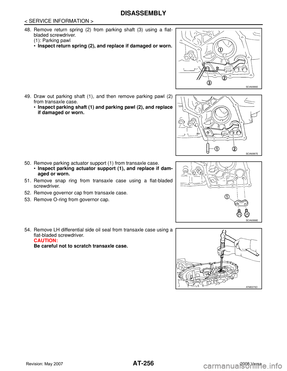
48. Remove return spring (2) from parking shaft (3) using a flat-
bladed screwdriver.
(1): Parking pawl
•Inspect return spring (2), and replace if damaged or worn.
49. Draw out parking shaft (1), and then remove parking pawl (2)
from transaxle case.
•Inspect parking shaft (1) and parking pawl (2), and replace
if damaged or worn.
50. Remove parking actuator support (1) from transaxle case.
•Inspect parking actuator support (1), and replace if dam-
aged or worn.
51. Remove snap ring from transaxle case using a flat-bladed
screwdriver.
52. Remove governor cap from transaxle case.
53. Remove O-ring from governor cap.
54. Remove LH differential side oil seal from transaxle case using a
flat-bladed screwdriver.
CAUTION:
Be careful not to scratch transaxle case.
SCIA6996E
SCIA6997E
SCIA6998E
ATM0076D
Page 269 of 2771
REPAIR FOR COMPONENT PARTS
AT-257
< SERVICE INFORMATION >
D
E
F
G
H
I
J
K
L
MA
B
AT
N
O
P
REPAIR FOR COMPONENT PARTS
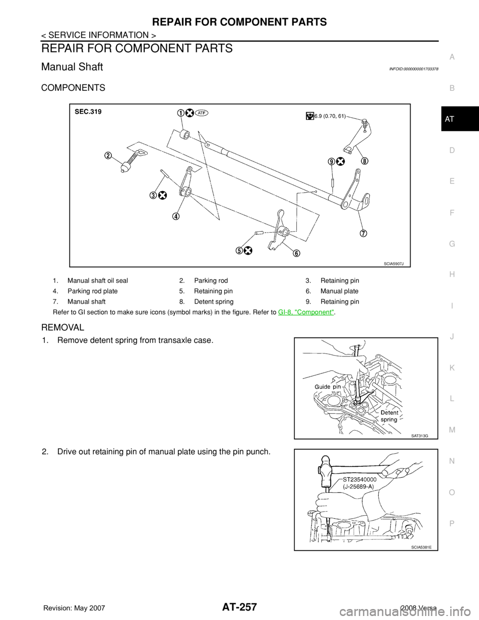
Manual ShaftINFOID:0000000001703378
COMPONENTS
REMOVAL
1. Remove detent spring from transaxle case.
2. Drive out retaining pin of manual plate using the pin punch.
1. Manual shaft oil seal 2. Parking rod 3. Retaining pin
4. Parking rod plate 5. Retaining pin 6. Manual plate
7. Manual shaft 8. Detent spring 9. Retaining pin
Refer to GI section to make sure icons (symbol marks) in the figure. Refer to GI-8, "
Component".
SCIA5907J
SAT313G
SCIA5381E
Page 270 of 2771
AT-258
< SERVICE INFORMATION >
REPAIR FOR COMPONENT PARTS
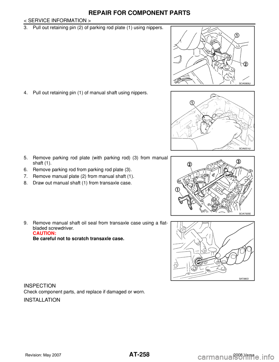
3. Pull out retaining pin (2) of parking rod plate (1) using nippers.
4. Pull out retaining pin (1) of manual shaft using nippers.
5. Remove parking rod plate (with parking rod) (3) from manual
shaft (1).
6. Remove parking rod from parking rod plate (3).
7. Remove manual plate (2) from manual shaft (1).
8. Draw out manual shaft (1) from transaxle case.
9. Remove manual shaft oil seal from transaxle case using a flat-
bladed screwdriver.
CAUTION:
Be careful not to scratch transaxle case.
INSPECTION
Check component parts, and replace if damaged or worn.
INSTALLATION
SCIA5806J
SCIA6514J
SCIA7005E
SAT080D
Trending: power, headlamp, cruise control, remote control, door cover, seat adjustment, Wiring diagram ecm
