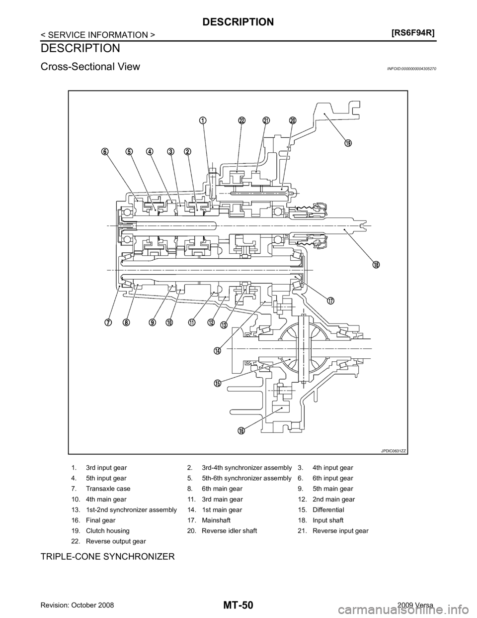
NISSAN TIIDA 2009 Service Repair Manual
TIIDA 2009
NISSAN
NISSAN
https://www.carmanualsonline.info/img/5/57398/w960_57398-0.png
NISSAN TIIDA 2009 Service Repair Manual
Trending: clock, change wheel, towing, manual transmission, warning light, 4 wheel drive, tire type
Page 3841 of 4331
PREPARATION
MT-47
< SERVICE INFORMATION >
[RS6F94R] D
E
F
G H
I
J
K L
M A
B MT
N
O P
Commercial Service Tool
INFOID:0000000004305268
Tool name Description
Socket Removing and installing drain plug
a: 8 mm (0.31 in)
b: 5 mm (0.20 in)
Spacer Removing mainshaft front bearing outer race
a: 25 mm (0.98 in) dia.
b: 25 mm (0.98 in)
Drift Installing bushing
a: 17 mm (0.67 in) dia.
Drift Installing input shaft front bearing
a: 35 mm (1.38 in) dia.
b: 25 mm (0.98 in) dia.
Drift Removing input shaft rear bearing
a: 24 mm (0.94 in) dia.
Drift • Removing differential side bearing inner
race (transaxle case side)
• Installing input shaft rear bearing
a: 43 mm (1.69 in) dia . PCIB1776E
PCIB1780E
S-NT063
S-NT065
PCIB1779E
NT109
Page 3842 of 4331
![NISSAN TIIDA 2009 Service Repair Manual MT-48< SERVICE INFORMATION >
[RS6F94R]
PREPARATION
Drift Installing differential side bearing inner race
(clutch housing side)
a: 45 mm (1.77 in) dia.
b: 39 mm (1.54 in) dia .
Drift Installing differ NISSAN TIIDA 2009 Service Repair Manual MT-48< SERVICE INFORMATION >
[RS6F94R]
PREPARATION
Drift Installing differential side bearing inner race
(clutch housing side)
a: 45 mm (1.77 in) dia.
b: 39 mm (1.54 in) dia .
Drift Installing differ](/img/5/57398/w960_57398-3841.png)
MT-48< SERVICE INFORMATION >
[RS6F94R]
PREPARATION
Drift Installing differential side bearing inner race
(clutch housing side)
a: 45 mm (1.77 in) dia.
b: 39 mm (1.54 in) dia .
Drift Installing differential side bearing inner race
(transaxle case side)
a: 52 mm (2.05 in) dia.
b: 45 mm (1.77 in) dia.
Puller Removing differential side bearing inner race
(clutch housing side)
Removing differential side bearing inner race
(transaxle case side)
Puller • Removing differential side bearing inner
race (clutch housing side)
• Removing differential side bearing inner
race (transaxle case side)
• Removing input shaft rear bearing
• Removing input shaft front bearing
• Removing mainshaft rear bearing inner race
• Removing 6th main gear
• Removing 4th main gear
• Removing 5th main gear
• Removing 1st main gear
• Removing 1st - 2nd synchronizer hub as-
sembly
• Removing 2nd main gear
• Removing 3rd main gear
• Removing mainshaft front bearing outer race
Remover • Removing bushing
• Removing mainshaft rear bearing outer
race
Power tool • Loosening bolts and nuts
Tool name
Description S-NT474
S-NT474
NT077
ZZB0823D
S-NT134
PBIC0190E
Page 3843 of 4331
MT
N
O P
NOISE, VIBRATION AND HARSHN
ESS (NVH) TROUBLESHOOTING
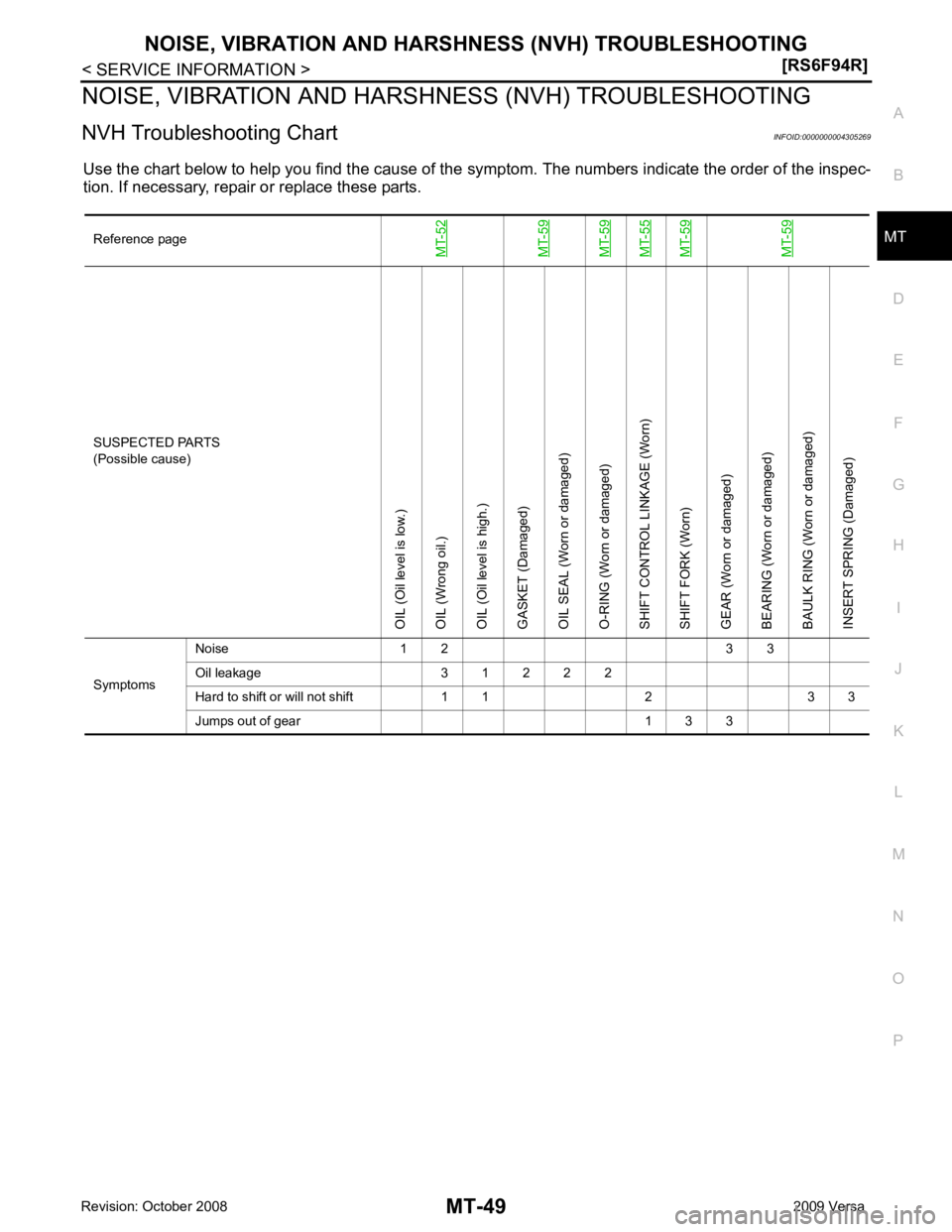
NVH Troubleshooting Chart INFOID:0000000004305269
Use the chart below to help you find the cause of the symptom. The numbers indicate the order of the inspec-
tion. If necessary, repair or replace these parts.
Reference pageMT-52MT-59MT-59MT-55MT-59MT-59 SUSPECTED PARTS
(Possible cause)
OIL (Oil level is low.)
OIL (Wrong oil.)
OIL (Oil level is high.)
GASKET (Damaged)
OIL SEAL (Worn or damaged)
O-RING (Worn or damaged)
SHIFT CONTROL LINKAGE (Worn)
SHIFT FORK (Worn)
GEAR (Worn or damaged)
BEARING (Worn or damaged)
BAULK RING (Worn or damaged)
INSERT SPRING (Damaged)
Symptoms Noise 1 2 3 3
Oil leakage 3 1 2 2 2
Hard to shift or will not shift 1 1 2 3 3
Jumps out of gear 1 3 3
Page 3844 of 4331
Page 3845 of 4331
MT
N
O P
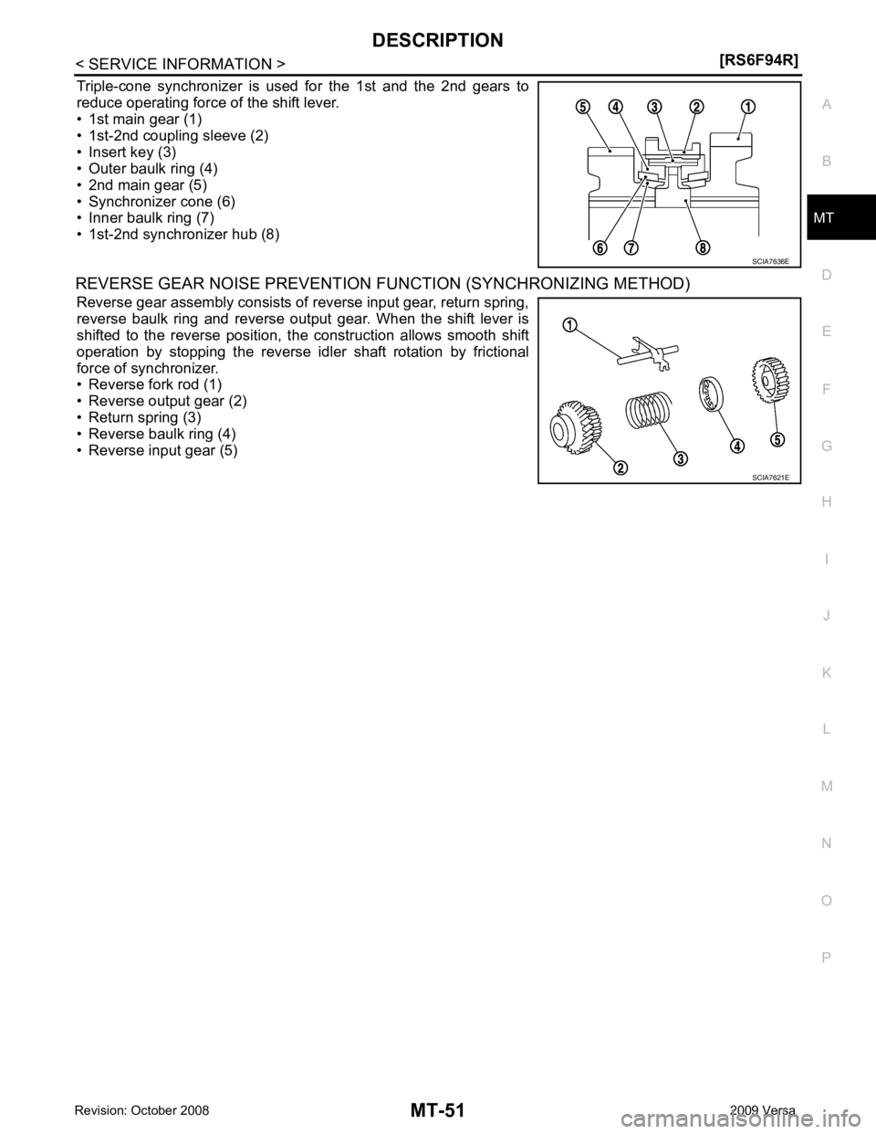
Triple-cone synchronizer is used for the 1st and the 2nd gears to
reduce operating force of the shift lever.
• 1st main gear (1)
• 1st-2nd coupling sleeve (2)
• Insert key (3)
• Outer baulk ring (4)
• 2nd main gear (5)
• Synchronizer cone (6)
• Inner baulk ring (7)
• 1st-2nd synchronizer hub (8)
REVERSE GEAR NOISE PREVENTION FUNCTION (SYNCHRONIZING METHOD)
Reverse gear assembly consists of reverse input gear, return spring,
reverse baulk ring and reverse output gear. When the shift lever is
shifted to the reverse position, the construction allows smooth shift
operation by stopping the reverse idler shaft rotation by frictional
force of synchronizer.
• Reverse fork rod (1)
• Reverse output gear (2)
• Return spring (3)
• Reverse baulk ring (4)
• Reverse input gear (5) SCIA7621E
Page 3846 of 4331
Dis-
assembly and Assembly " .
CAUTION:
Do not reuse gasket.
FILLING
1. Remove filler plug (1). Fill with new oil until oil level reaches the specified limit at filler plug hole as shown.
2. After refilling oil, check oil level. Install a new gasket on filler plug (1), then install it into transaxle. Tighten filler plug to specifica-
tion. Refer to MT-59, " Disassembly and Assembly " .
CAUTION:
Do not reuse gasket.
Checking M/T Oil INFOID:0000000004305272
OIL LEAKAGE AND OIL LEVEL
1. Make sure that oil is not leaking from transaxle or around it.
2. Remove filler plug (1) and check oil level at filler plug hole as shown.
CAUTION:
Do not start engine wh ile checking oil level.
3. Install a new gasket onto filler plug (1) and install it into tran-
saxle. Tighten filler plug to specification. Refer to MT-59, " Disas-
sembly and Assembly " .
CAUTION:
Do not reuse gasket. Fluids and Lubricants "
Page 3847 of 4331
MT
N
O P
SIDE OIL SEAL
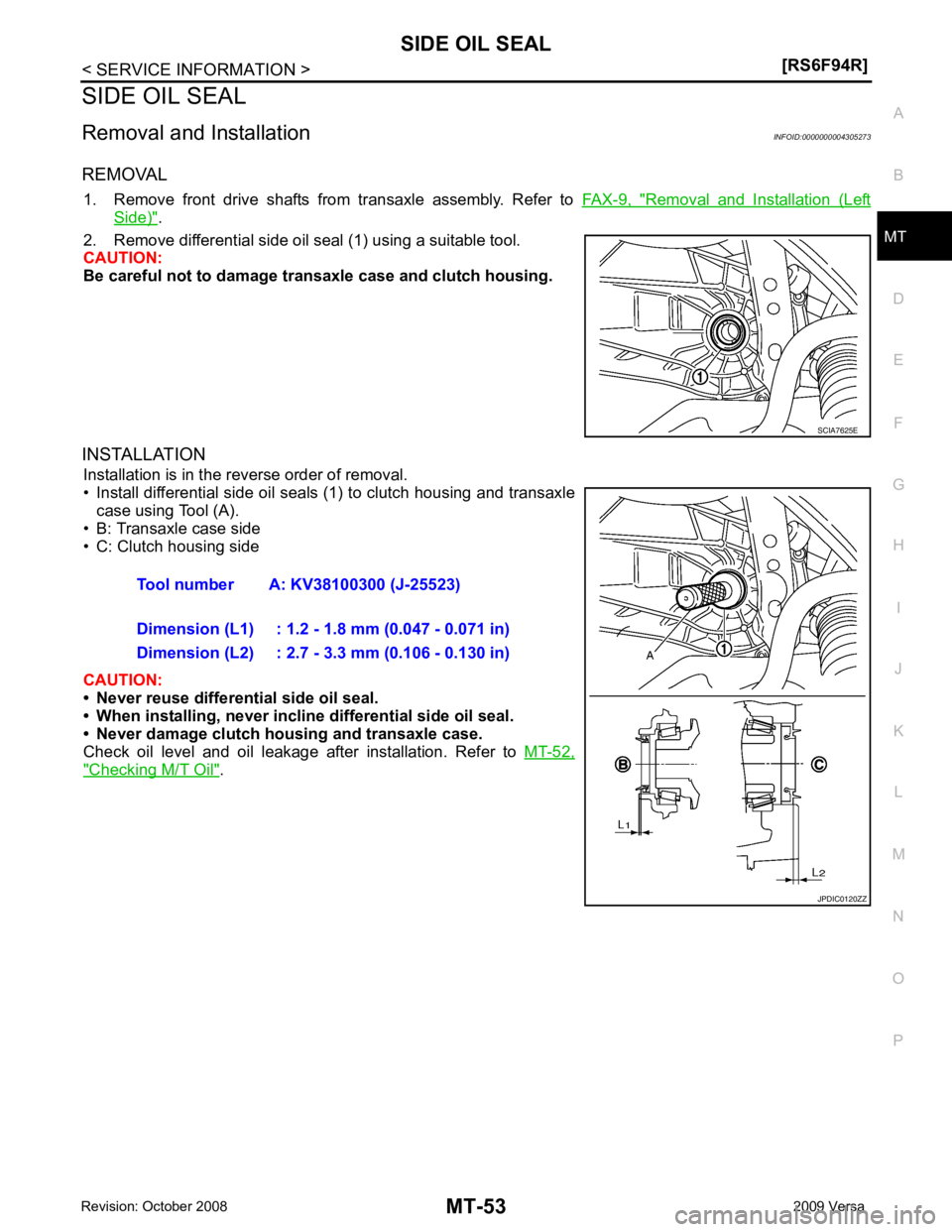
Removal and Installation INFOID:0000000004305273
REMOVAL 1. Remove front drive shafts from transaxle assembly. Refer to FAX-9, " Removal and Installation (Left
Side) " .
2. Remove differential side oil seal (1) using a suitable tool.
CAUTION:
Be careful not to damage transaxle case and clutch housing.
INSTALLATION Installation is in the reverse order of removal.
• Install differential side oil seals (1) to clutch housing and transaxle case using Tool (A).
• B: Transaxle case side
• C: Clutch housing side
CAUTION:
• Never reuse differential side oil seal.
• When installing, never inclin e differential side oil seal.
• Never damage clutch housing and transaxle case.
Check oil level and oil leakage after installation. Refer to MT-52," Checking M/T Oil " .
Page 3848 of 4331
Disassembly and Assembly "
Page 3849 of 4331
MT
N
O P
CONTROL LINKAGE
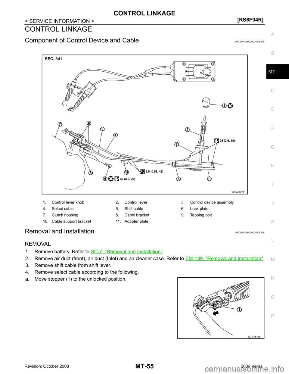
Component of Contro l Device and Cable INFOID:0000000004305275
Removal and Installation INFOID:0000000004305276
REMOVAL 1. Remove battery. Refer to SC-7, " Removal and Installation " .
2. Remove air duct (front), air duct (Inlet) and air cleaner case. Refer to EM-139, " Removal and Installation " .
3. Remove shift cable from shift lever.
4. Remove select cable according to the following.
a. Move stopper (1) to the unlocked position. 1. Control lever knob 2. Control lever 3. Control device assembly
4. Select cable 5. Shift cable 6. Lock plate
7. Clutch housing 8. Cable bracket 9. Tapping bolt
10. Cable support bracket 11. Adapter plate SCIA7842E
Page 3850 of 4331
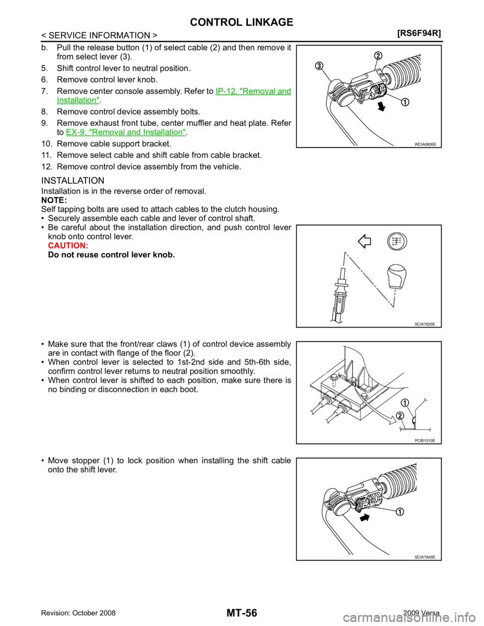
Removal and
Installation " .
8. Remove control device assembly bolts.
9. Remove exhaust front tube, center muffler and heat plate. Refer to EX-9, " Removal and Installation " .
10. Remove cable support bracket.
11. Remove select cable and shift cable from cable bracket.
12. Remove control device assembly from the vehicle.
INSTALLATION
Installation is in the reverse order of removal.
NOTE:
Self tapping bolts are used to attach cables to the clutch housing.
• Securely assemble each cable and lever of control shaft.
• Be careful about the installation direction, and push control lever knob onto control lever.
CAUTION:
Do not reuse control lever knob.
• Make sure that the front/rear claws (1) of control device assembly are in contact with flange of the floor (2).
• When control lever is selected to 1st-2nd side and 5th-6th side,
confirm control lever returns to neutral position smoothly.
• When control lever is shifted to each position, make sure there is
no binding or disconnection in each boot.
• Move stopper (1) to lock position when installing the shift cable onto the shift lever. SCIA7630E
SCIA7846E
Trending: navigation, 4wd, hood open, key battery, Ecm f11 connector, phone, power steering fluid
![NISSAN TIIDA 2009 Service Repair Manual PREPARATION
MT-47
< SERVICE INFORMATION >
[RS6F94R] D
E
F
G H
I
J
K L
M A
B MT
N
O P
Commercial Service Tool
INFOID:0000000004305268
Tool name Description
Socket Removing and installing drain plug
a: NISSAN TIIDA 2009 Service Repair Manual PREPARATION
MT-47
< SERVICE INFORMATION >
[RS6F94R] D
E
F
G H
I
J
K L
M A
B MT
N
O P
Commercial Service Tool
INFOID:0000000004305268
Tool name Description
Socket Removing and installing drain plug
a:](/img/5/57398/w960_57398-3840.png)
![NISSAN TIIDA 2009 Service Repair Manual MT-48< SERVICE INFORMATION >
[RS6F94R]
PREPARATION
Drift Installing differential side bearing inner race
(clutch housing side)
a: 45 mm (1.77 in) dia.
b: 39 mm (1.54 in) dia .
Drift Installing differ NISSAN TIIDA 2009 Service Repair Manual MT-48< SERVICE INFORMATION >
[RS6F94R]
PREPARATION
Drift Installing differential side bearing inner race
(clutch housing side)
a: 45 mm (1.77 in) dia.
b: 39 mm (1.54 in) dia .
Drift Installing differ](/img/5/57398/w960_57398-3841.png)
