NISSAN TIIDA 2009 Service Repair Manual
TIIDA 2009
NISSAN
NISSAN
https://www.carmanualsonline.info/img/5/57398/w960_57398-0.png
NISSAN TIIDA 2009 Service Repair Manual
Trending: jump start, seat memory, fog light bulb, wiper fluid, fuse box, wiring diagram, octane
Page 3801 of 4331
MT
N
O P
NOISE, VIBRATION AND HARSHN
ESS (NVH) TROUBLESHOOTING
NVH Troubleshooting Chart INFOID:0000000004784215
Use the chart below to help you find the cause of the symptom. The numbers indicate the order of the inspec-
tion. If necessary, repair or replace these parts.
Reference pageMT-17MT-17MT-13MT-17MT-17 SUSPECTED PARTS
(Possible cause)
OIL (Oil level is low.)
OIL (Wrong oil.)
OIL (Oil level is high.)
GASKET (Damaged)
OIL SEAL (Worn or damaged)
O-RING (Worn or damaged)
SHIFT CONTROL LINKAGE (Worn)
SHIFT FORK (Worn)
GEAR (Worn or damaged)
BEARING (Worn or damaged)
BAULK RING (Worn or damaged)
INSERT SPRING (Damaged)
Symptoms Noise 1 2 3 3
Oil leakage 3 1 2 2 2
Hard to shift or will not shift 1 1 2 3 3
Jumps out of gear 1 2 2
Page 3802 of 4331
Page 3803 of 4331
MT
N
O P
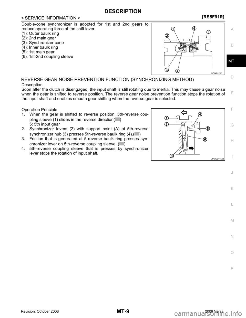
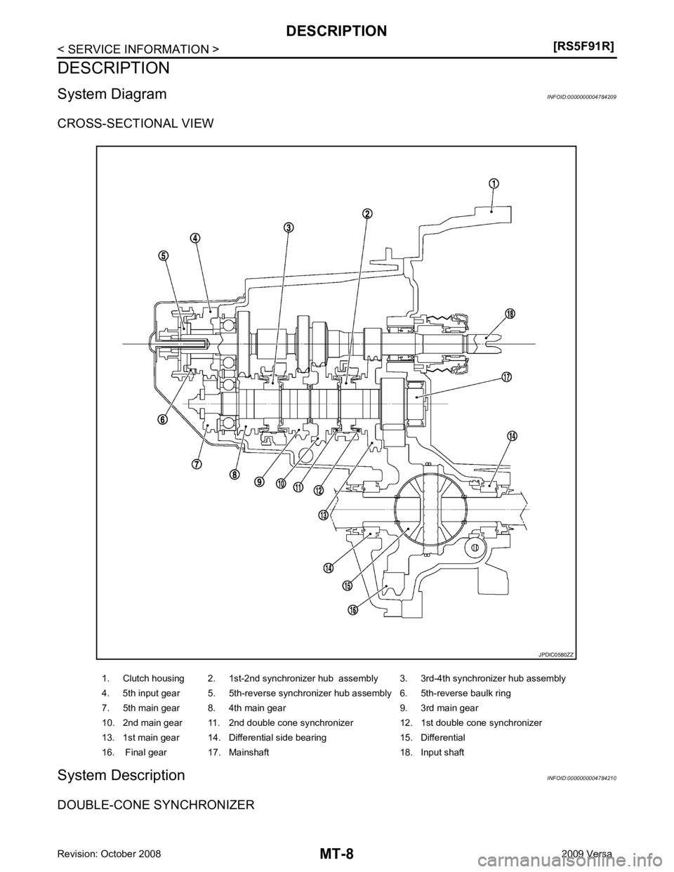
Double-cone synchronizer is adopted for 1st and 2nd gears to
reduce operating force of the shift lever.
(1): Outer baulk ring
(2): 2nd main gear
(3): Synchronizer cone
(4): Inner baulk ring
(5): 1st main gear
(6): 1st-2nd coupling sleeve
REVERSE GEAR NOISE PREVENTION FUNCTION (SYNCHRONIZING METHOD)
Description
Soon after the clutch is disengaged, the input shaft is still rotating due to inertia. This may cause a gear noise
when the gear is shifted to reverse position. The reve rse gear noise prevention function stops the rotation of
the input shaft and enables smooth gear shifting when the reverse gear is selected.
Operation Principle
1. When the gear is shifted to reverse position, 5th-reverse cou-
pling sleeve (1) slides in the reverse direction( )
5: 5th input gear
2. Synchronizer levers (2) with support point (A) at 5th-reverse
synchronizer hub (3) presses 5th-reverse baulk ring (4).( )
3. Friction that is generated at 5-reverse baulk ring presses syn-
chronizer lever on 5th-reverse coupling sleeve. ( )
4. 5th-reverse coupling sleeve that is presses by synchronizer
lever stops the rotation of input shaft. JPDIC0415ZZ
Page 3804 of 4331
![NISSAN TIIDA 2009 Service Repair Manual MT-10< SERVICE INFORMATION >
[RS5F91R]
M/T OIL
M/T OIL
Draining INFOID:0000000004784220
1. Start engine and let it run to warm up transaxle.
2. Stop engine. Remove drain plug (1) and drain oil.
3. Set NISSAN TIIDA 2009 Service Repair Manual MT-10< SERVICE INFORMATION >
[RS5F91R]
M/T OIL
M/T OIL
Draining INFOID:0000000004784220
1. Start engine and let it run to warm up transaxle.
2. Stop engine. Remove drain plug (1) and drain oil.
3. Set](/img/5/57398/w960_57398-3803.png)
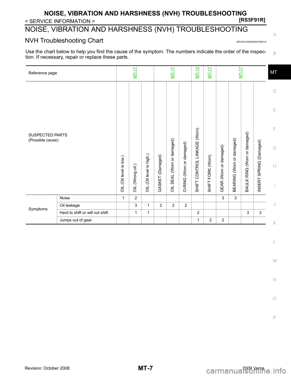
MT-10< SERVICE INFORMATION >
[RS5F91R]
M/T OIL
M/T OIL
Draining INFOID:0000000004784220
1. Start engine and let it run to warm up transaxle.
2. Stop engine. Remove drain plug (1) and drain oil.
3. Set a new gasket on drain plug (1) and install it to transaxle and tighten drain plug to the specified torque. Refer to MT-17, " Dis-
assembly and Assembly " .
CAUTION:
Do not reuse gasket.
Refilling INFOID:0000000004784221
1. Remove filler plug (1). Fill with new oil until oil level reaches the specified limit near filler plug hole as shown.
2. After refilling oil, check oil level.
3. Set a new gasket on filler plug (1), then install it to transaxle and tighten to the specified torque. Refer to MT-17, " Disassembly
and Assembly " .
CAUTION:
Do not reuse gasket.
Inspection INFOID:0000000004784222
LEAKAGE
Make sure that oil is not leaking from transaxle or around it.
LEVEL
1. Remove filler plug (1) and check oil level at filler plug hole as shown.
CAUTION:
Do not start engine wh ile checking oil level.
2. Set a new gasket on filler plug (1) and install it to the transaxle case.
CAUTION:
Do not reuse gasket.
3. Tighten filler plug to the specified torque. Refer to MT-17, " Dis-
assembly and Assembly " . PCIB1504E
Oil grade and capacity : Refer to
MA-14, " Fluids and
Lubricants " .
SCIA7119E
SCIA7119E
Page 3805 of 4331
MT
N
O P
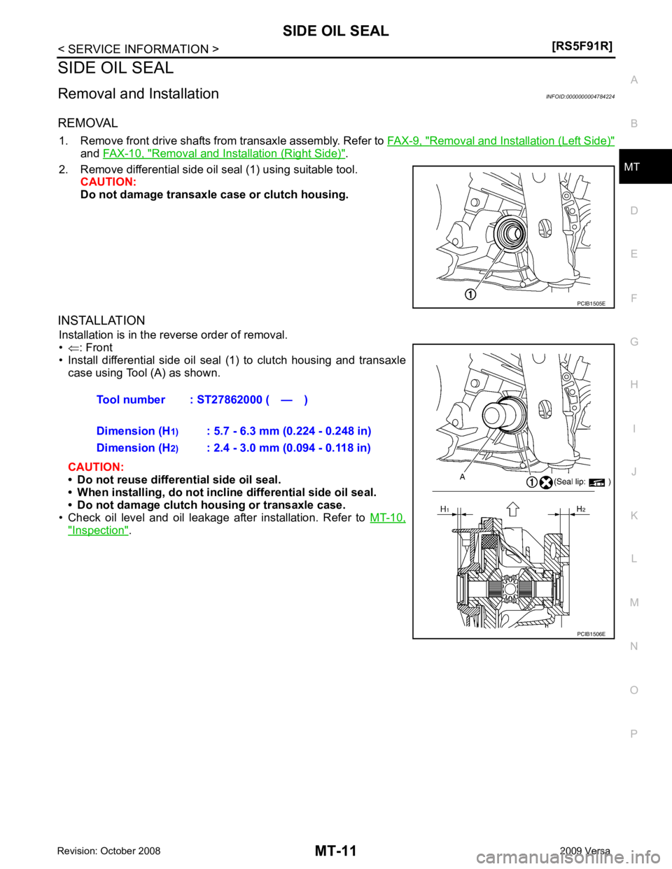
SIDE OIL SEAL
Removal and Installation INFOID:0000000004784224
REMOVAL 1. Remove front drive shafts from transaxle assembly. Refer to FAX-9, " Removal and Installation (Left Side) "
and
FAX-10, " Removal and Installation (Right Side) " .
2. Remove differential side oil seal (1) using suitable tool. CAUTION:
Do not damage transaxle case or clutch housing.
INSTALLATION Installation is in the reverse order of removal.
• ⇐ : Front
• Install differential side oil seal (1) to clutch housing and transaxle
case using Tool (A) as shown.
CAUTION:
• Do not reuse differential side oil seal.
• When installing, do not incline differential side oil seal.
• Do not damage clutch housing or transaxle case.
• Check oil level and oil leakage after installation. Refer to MT-10," Inspection " .
Page 3806 of 4331
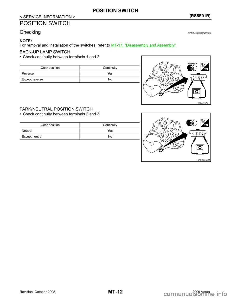
Disassembly and Assembly "
Page 3807 of 4331
MT
N
O P
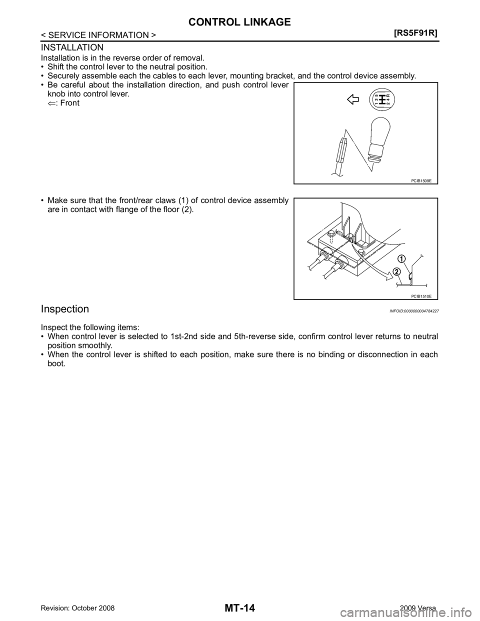
CONTROL LINKAGE
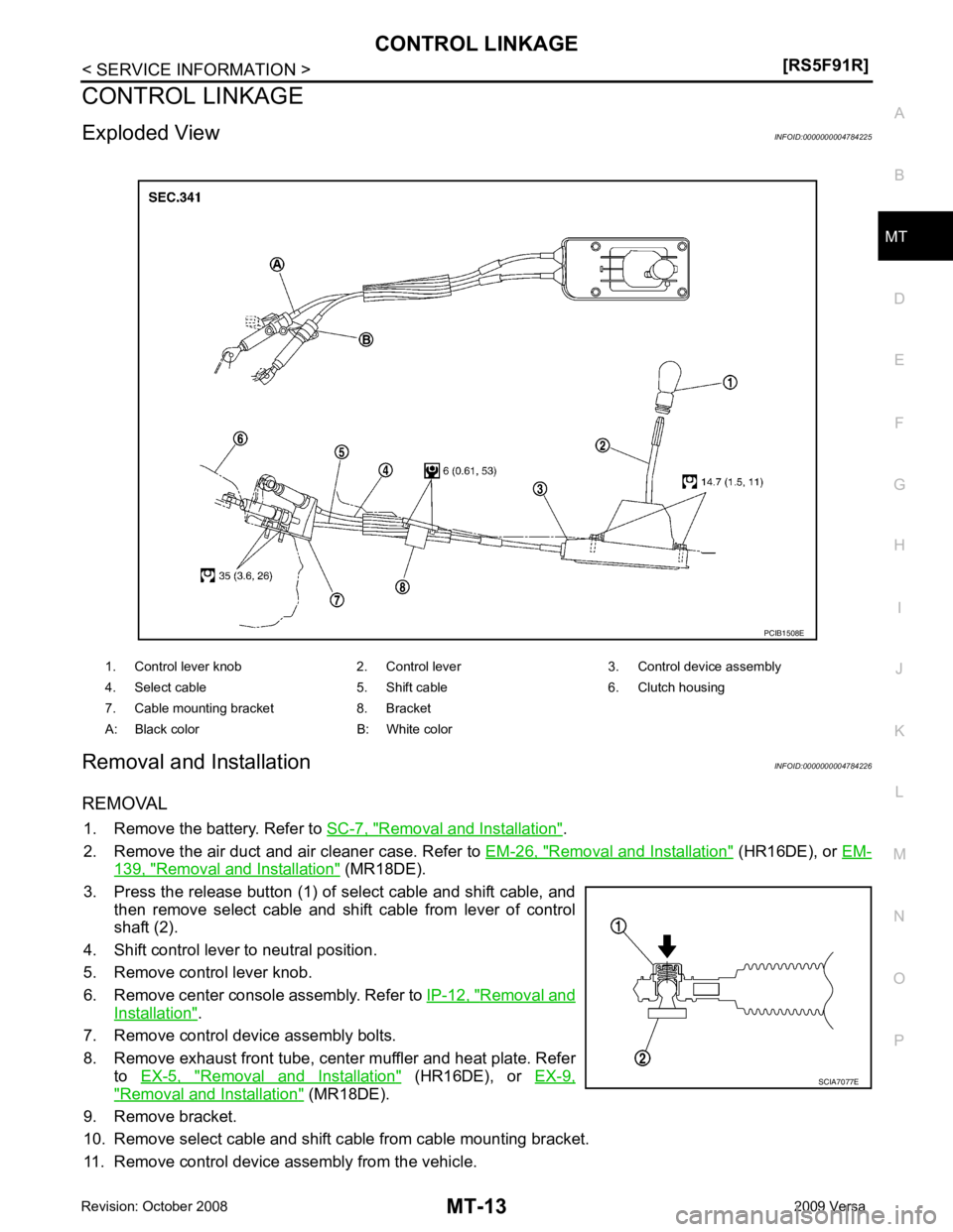
Exploded View INFOID:0000000004784225
Removal and Installation INFOID:0000000004784226
REMOVAL 1. Remove the battery. Refer to SC-7, " Removal and Installation " .
2. Remove the air duct and air cleaner case. Refer to EM-26, " Removal and Installation " (HR16DE), or
EM- 139, " Removal and Installation " (MR18DE).
3. Press the release button (1) of select cable and shift cable, and then remove select cable and shift cable from lever of control
shaft (2).
4. Shift control lever to neutral position.
5. Remove control lever knob.
6. Remove center console assembly. Refer to IP-12, " Removal and
Installation " .
7. Remove control device assembly bolts.
8. Remove exhaust front tube, cent er muffler and heat plate. Refer
to EX-5, " Removal and Installation " (HR16DE), or
EX-9," Removal and Installation " (MR18DE).
9. Remove bracket.
10. Remove select cable and shift c able from cable mounting bracket.
11. Remove control device assembly from the vehicle. 1. Control lever knob 2. Control lever 3. Control device assembly
4. Select cable 5. Shift cable 6. Clutch housing
7. Cable mounting bracket 8. Bracket
A: Black color B: White color
Page 3808 of 4331
Page 3809 of 4331
MT
N
O P
AIR BREATHER HOSE
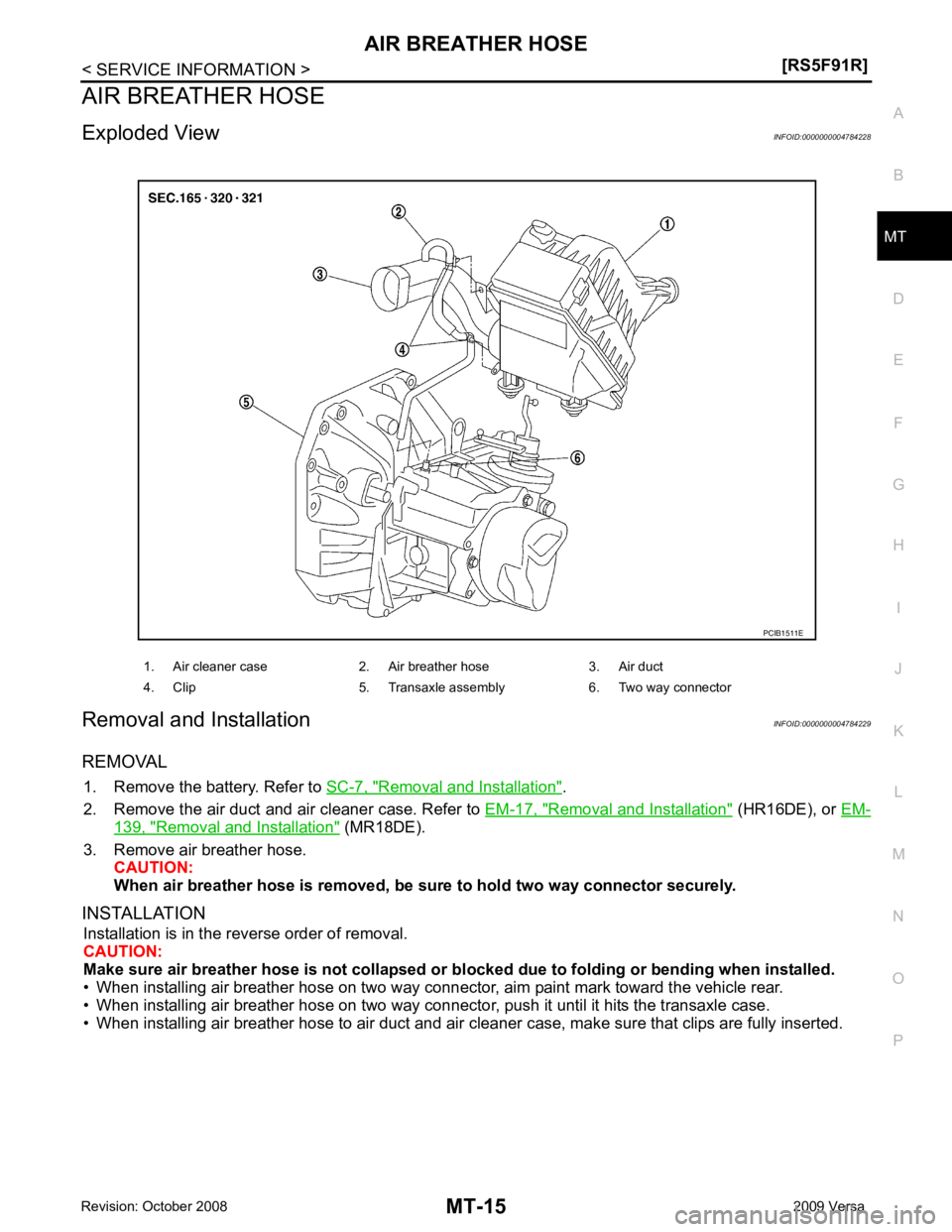
Exploded View INFOID:0000000004784228
Removal and Installation INFOID:0000000004784229
REMOVAL 1. Remove the battery. Refer to SC-7, " Removal and Installation " .
2. Remove the air duct and air cleaner case. Refer to EM-17, " Removal and Installation " (HR16DE), or
EM- 139, " Removal and Installation " (MR18DE).
3. Remove air breather hose. CAUTION:
When air breather hose is removed, be su re to hold two way connector securely.
INSTALLATION Installation is in the reverse order of removal.
CAUTION:
Make sure air breather hose is not collapsed or bl ocked due to folding or bending when installed.
• When installing air breather hose on two way connector, aim paint mark toward the vehicle rear.
• When installing air breather hose on two way connecto r, push it until it hits the transaxle case.
• When installing air breather hose to air duct and air cleaner case, make sure that clips are fully inserted. 1. Air cleaner case 2. Air breather hose 3. Air duct
4. Clip 5. Transaxle assembly 6. Two way connector
Page 3810 of 4331
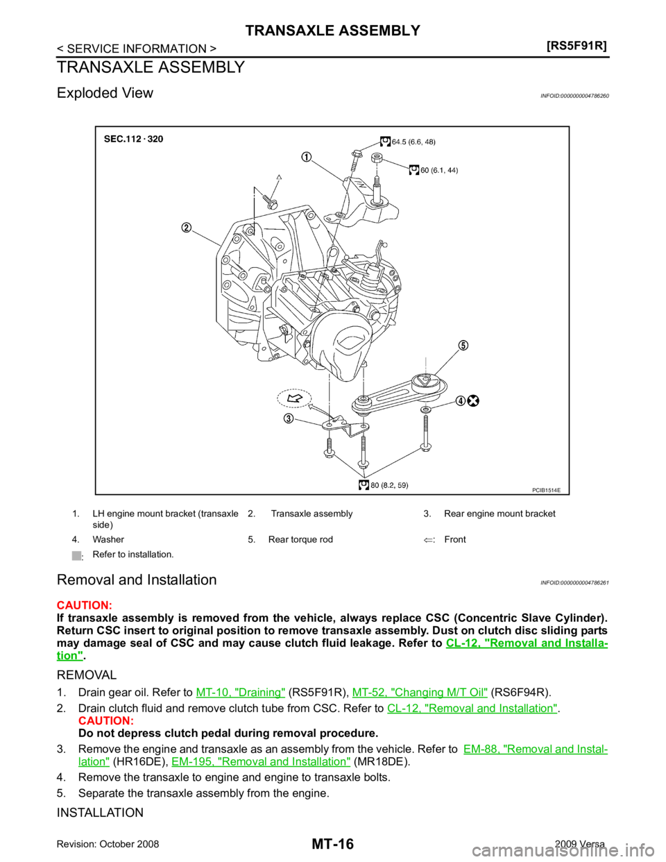
Removal and Installa-
tion " .
REMOVAL
1. Drain gear oil. Refer to MT-10, " Draining " (RS5F91R),
MT-52, " Changing M/T Oil " (RS6F94R).
2. Drain clutch fluid and remove clutch tube from CSC. Refer to CL-12, " Removal and Installation " .
CAUTION:
Do not depress clutch pedal during removal procedure.
3. Remove the engine and transaxle as an assembly from the vehicle. Refer to EM-88, " Removal and Instal-
lation " (HR16DE),
EM-195, " Removal and Installation " (MR18DE).
4. Remove the transaxle to engine and engine to transaxle bolts.
5. Separate the transaxle assembly from the engine.
INSTALLATION 1. LH engine mount bracket (transaxle
side) 2. Transaxle assembly 3. Rear engine mount bracket
4. Washer 5. Rear torque rod ⇐: Front
: Refer to installation.
Trending: rear view mirror, transmission, brake, CD player, coolant reservoir, manual radio set, bumper

![NISSAN TIIDA 2009 Service Repair Manual MT-10< SERVICE INFORMATION >
[RS5F91R]
M/T OIL
M/T OIL
Draining INFOID:0000000004784220
1. Start engine and let it run to warm up transaxle.
2. Stop engine. Remove drain plug (1) and drain oil.
3. Set NISSAN TIIDA 2009 Service Repair Manual MT-10< SERVICE INFORMATION >
[RS5F91R]
M/T OIL
M/T OIL
Draining INFOID:0000000004784220
1. Start engine and let it run to warm up transaxle.
2. Stop engine. Remove drain plug (1) and drain oil.
3. Set](/img/5/57398/w960_57398-3803.png)
