NISSAN TIIDA 2009 Service Repair Manual
Manufacturer: NISSAN, Model Year: 2009, Model line: TIIDA, Model: NISSAN TIIDA 2009Pages: 4331, PDF Size: 58.04 MB
Page 3821 of 4331
MT
N
O P
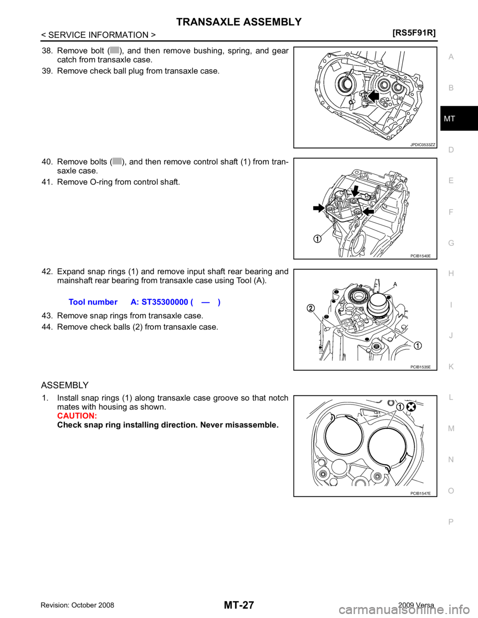
38. Remove bolt ( ), and then remove bushing, spring, and gear
catch from transaxle case.
39. Remove check ball plug from transaxle case.
40. Remove bolts ( ), and then remove control shaft (1) from tran- saxle case.
41. Remove O-ring from control shaft.
42. Expand snap rings (1) and remove input shaft rear bearing and mainshaft rear bearing from transaxle case using Tool (A).
43. Remove snap rings from transaxle case.
44. Remove check balls (2) from transaxle case.
ASSEMBLY 1. Install snap rings (1) along transaxle case groove so that notch mates with housing as shown.
CAUTION:
Check snap ring installing direction. Never misassemble.
Page 3822 of 4331
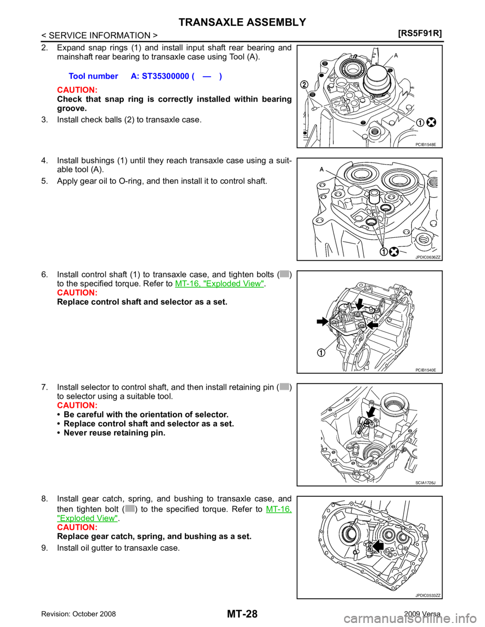
Exploded View " .
CAUTION:
Replace control shaft and selector as a set.
7. Install selector to control shaft, and then install retaining pin ( ) to selector using a suitable tool.
CAUTION:
• Be careful with the orientation of selector.
• Replace control shaft and selector as a set.
• Never reuse retaining pin.
8. Install gear catch, spring, and bushing to transaxle case, and then tighten bolt ( ) to the specified torque. Refer to MT-16," Exploded View " .
CAUTION:
Replace gear catch, spring, and bushing as a set.
9. Install oil gutter to transaxle case. Tool number A: ST35300000 ( — )
JPDIC0636ZZ
PCIB1540E
JPDIC0533ZZ
Page 3823 of 4331
MT
N
O P
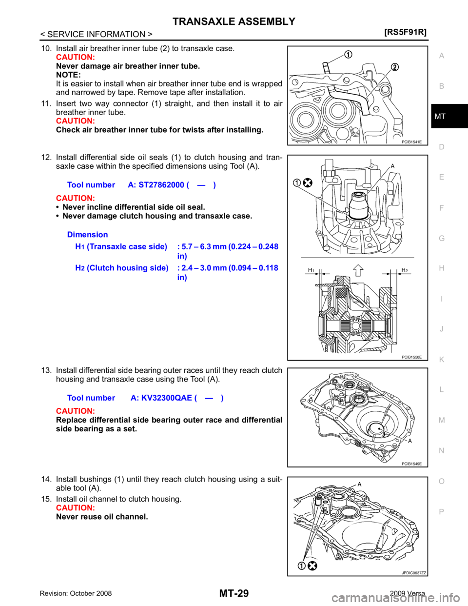
10. Install air breather inner tube (2) to transaxle case.
CAUTION:
Never damage air breather inner tube.
NOTE:
It is easier to install when air breather inner tube end is wrapped
and narrowed by tape. Remove tape after installation.
11. Insert two way connector (1) straight, and then install it to air breather inner tube.
CAUTION:
Check air breather inner tube fo r twists after installing.
12. Install differential side oil seals (1) to clutch housing and tran- saxle case within the specified dimensions using Tool (A).
CAUTION:
• Never incline differential side oil seal.
• Never damage clutch housing and transaxle case.
13. Install differential side bearing outer races until they reach clutch housing and transaxle case using the Tool (A).
CAUTION:
Replace differential side bearing outer race and differential
side bearing as a set.
14. Install bushings (1) until they reach clutch housing using a suit- able tool (A).
15. Install oil channel to clutch housing. CAUTION:
Never reuse oil channel. JPDIC0637ZZ
Page 3824 of 4331
![NISSAN TIIDA 2009 Service Repair Manual MT-30< SERVICE INFORMATION >
[RS5F91R]
TRANSAXLE ASSEMBLY
16. Install mainshaft front bearing so that it becomes even to clutch housing surface using Tool (A) .
17. Install input shaft front bearing s NISSAN TIIDA 2009 Service Repair Manual MT-30< SERVICE INFORMATION >
[RS5F91R]
TRANSAXLE ASSEMBLY
16. Install mainshaft front bearing so that it becomes even to clutch housing surface using Tool (A) .
17. Install input shaft front bearing s](/img/5/57398/w960_57398-3823.png)
MT-30< SERVICE INFORMATION >
[RS5F91R]
TRANSAXLE ASSEMBLY
16. Install mainshaft front bearing so that it becomes even to clutch housing surface using Tool (A) .
17. Install input shaft front bearing so that it becomes even to clutch
housing surface using Tool (A).
18. Install pinion gear and pinion shaft to clutch housing.
19. Install final drive assembly (1) to clutch housing.
20. Install dowel pins (2) and magnet to clutch housing.
21. Install reverse gear assembly to clutch housing, and then install retaining pin to clutch housing using a suitable tool.
CAUTION:
Never reuse retaining pin.
22. Install 1st-2nd shift fork to 1st-2nd fork rod, and then install retaining pin to 1st-2nd shift fork.
CAUTION:
• Never reuse retaining pin.
• Replace 1st-2nd fork rod and 1st-2nd shift fork as a set.
23. Set 1st-2nd fork rod assembly (1) onto mainshaft assembly (2), and then install them to clutch housing.Tool number A: ST33400001 (J-26082) PCIB1544E
Tool number A: KV40100900 ( — )
PCIB1545E
PCIB1533E
MCIB0033E
PCIB1532E
Page 3825 of 4331
![NISSAN TIIDA 2009 Service Repair Manual TRANSAXLE ASSEMBLY
MT-31
< SERVICE INFORMATION >
[RS5F91R] D
E
F
G H
I
J
K L
M A
B MT
N
O P
24. Install lock pins ( ) to clutch housing.
25. Install 3rd-4th shift fork to 3rd-4th fork rod, and NISSAN TIIDA 2009 Service Repair Manual TRANSAXLE ASSEMBLY
MT-31
< SERVICE INFORMATION >
[RS5F91R] D
E
F
G H
I
J
K L
M A
B MT
N
O P
24. Install lock pins ( ) to clutch housing.
25. Install 3rd-4th shift fork to 3rd-4th fork rod, and](/img/5/57398/w960_57398-3824.png)
TRANSAXLE ASSEMBLY
MT-31
< SERVICE INFORMATION >
[RS5F91R] D
E
F
G H
I
J
K L
M A
B MT
N
O P
24. Install lock pins ( ) to clutch housing.
25. Install 3rd-4th shift fork to 3rd-4th fork rod, and then install retaining pin to 3rd-4th shift fork.
CAUTION:
• Never reuse retaining pin.
• Replace 3rd-4th fork rod and 3rd-4th shift fork as a set.
26. Install 3rd-4th fork rod assembly (1), 3rd-4th coupling sleeve (2), and input shaft assembly (3) to clutch housing according to the
following procedures.
a. Pull 1st-2nd fork rod (4) up, and then maintain the neutral posi- tion.
b. Set 3rd-4th fork rod assembly onto 3rd-4th coupling sleeve, and then install them together with input shaft assembly to clutch
housing.
CAUTION:
• Set lock pin (3rd-4th fork rod side) onto 1st-2nd fork rod groove and then install 3rd-4th fork rod assembly.
• Be careful with the orientat ion of 3rd-4th coupling sleeve.
- A: 4th main gear side
- B: 3rd main gear side
• Install 3rd input gear of in put shaft assembly so that it is
set under reverse main gear of 3rd-4th coupling sleeve.
• Replace 3rd-4th coupling sl eeve and 3rd-4th synchronizer
hub as a set.
c. Install springs and insert keys to 3rd-4th synchronizer hub.
d. Apply gear oil to 4th baulk ring.
e. Install 4th baulk ring.
27. Install 5th-reverse fork rod (1) to clutch housing according to the following procedures.
CAUTION:
Replace 5th-reverse fork rod and 5th-reverse shift fork as a
set.
a. Pull gear of reverse gear assembly (2) up.
b. Temporarily install 5th-reverse fork rod to clutch housing. JPDIC0534ZZ
PCIB1628E
PCIB1551E
MCIB0061E
PCIB1629E
Page 3826 of 4331
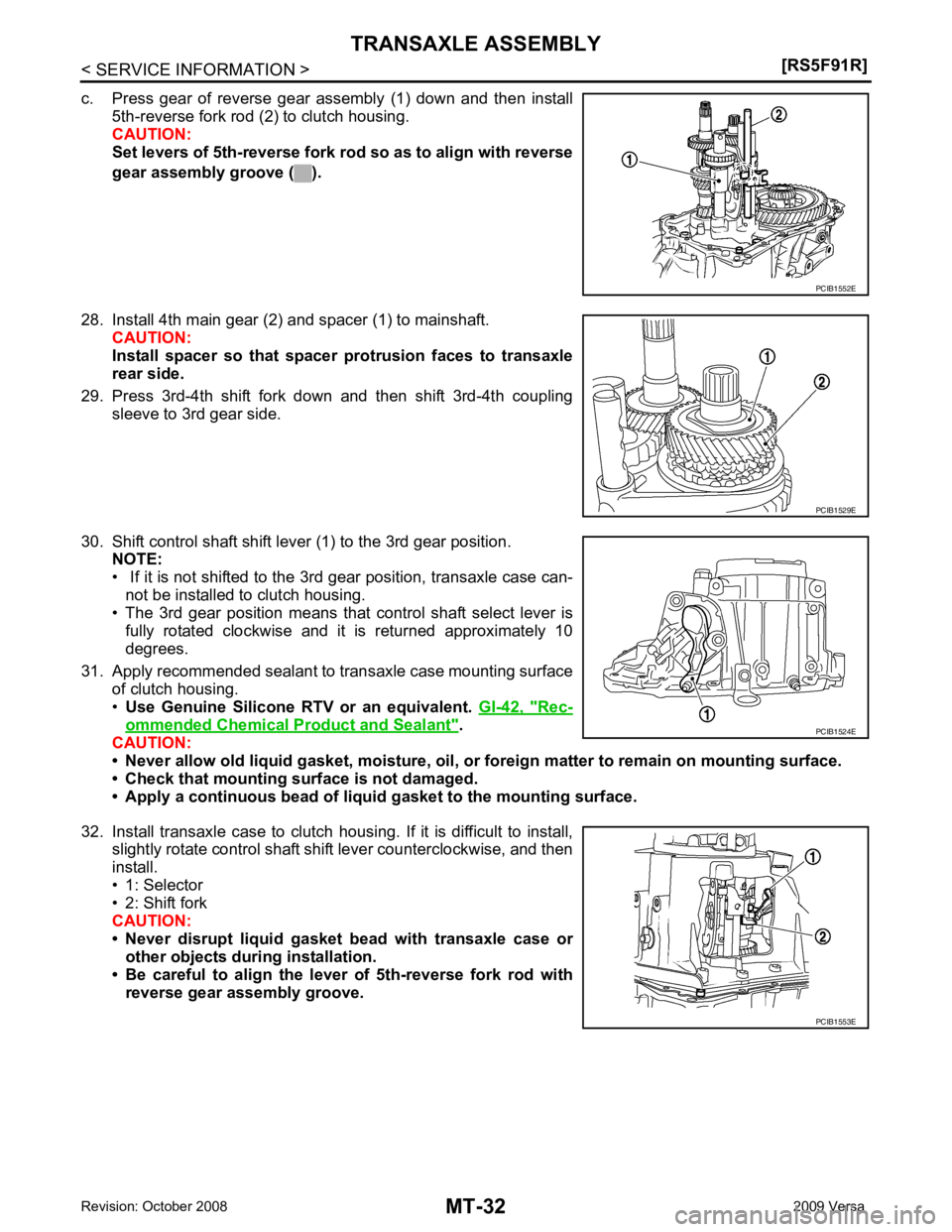
Rec-
ommended Chemical Product and Sealant " .
CAUTION:
• Never allow old liquid gasket, moisture, oil, or foreign matter to remain on mounting surface.
• Check that mounting surface is not damaged.
• Apply a continuous bead of liqu id gasket to the mounting surface.
32. Install transaxle case to clutch housing. If it is difficult to install, slightly rotate control shaft shift lever counterclockwise, and then
install.
• 1: Selector
• 2: Shift fork
CAUTION:
• Never disrupt liquid gasket bead with transaxle case or
other objects during installation.
• Be careful to align the lever of 5th-reverse fork rod with
reverse gear assembly groove. PCIB1529E
PCIB1524E
PCIB1553E
Page 3827 of 4331
![NISSAN TIIDA 2009 Service Repair Manual TRANSAXLE ASSEMBLY
MT-33
< SERVICE INFORMATION >
[RS5F91R] D
E
F
G H
I
J
K L
M A
B MT
N
O P
33. Rotate input shaft so that bearing and shaft fit each other, and
then tighten transaxle bolts NISSAN TIIDA 2009 Service Repair Manual TRANSAXLE ASSEMBLY
MT-33
< SERVICE INFORMATION >
[RS5F91R] D
E
F
G H
I
J
K L
M A
B MT
N
O P
33. Rotate input shaft so that bearing and shaft fit each other, and
then tighten transaxle bolts](/img/5/57398/w960_57398-3826.png)
TRANSAXLE ASSEMBLY
MT-33
< SERVICE INFORMATION >
[RS5F91R] D
E
F
G H
I
J
K L
M A
B MT
N
O P
33. Rotate input shaft so that bearing and shaft fit each other, and
then tighten transaxle bolts ( ) to the specified torque. Refer to
MT-16, " Exploded View " .
34. Apply recommended sealant to position switch thread and check ball plug thread. Tighten them to transaxle case and them to the
specified torque. Refer to MT-16, " Exploded View " .
• Use Genuine Silicone RTV or an equivalent. GI-42, " Rec-
ommended Chemical Product and Sealant " .
CAUTION:
Never allow old liquid gasket, mo isture, oil, or foreign mat-
ter to remain on thread.
35. Apply gear oil to mainshaft spline.
36. Install 5th main gear (1) to mainshaft using a suitable bolt (A) [M10 x 1.0] and a suitable nut (B).
37. Install adapter plate (1), bushing (2), and 5th input gear (3) to input shaft.
CAUTION:
Be careful with the orientation of adapter plate.
• : Transaxle case side
38. Install 5th-reverse synchronizer hub, 5th-reverse c oupling sleeve, and 5th-reverse shift fork according to
the following procedures.
a. Apply gear oil to 5th-reverse baulk ring.
b. Install 5th-reverse baulk ring (1) to 5th input gear. CAUTION:
Be careful with the orientation of 5th-reverse baulk ring.
c. Install synchronizer levers (2) to 5th-reverse synchronizer hub (3).
CAUTION:
• Replace 5th-reverse synchronizer hub and 5th-reverse coupling sleeve as a set.
• Be careful with the orientation of synchronizer lever.
• : 5th-reverse synchronizer hub side
d. Install 5th-reverse synchronizer hub assembly and washer to input shaft.
CAUTION: JPDIC0610ZZ
PCIB1554E
PCIB1555E
JPDIC0421ZZ
Page 3828 of 4331
![NISSAN TIIDA 2009 Service Repair Manual MT-34< SERVICE INFORMATION >
[RS5F91R]
TRANSAXLE ASSEMBLY
• Be careful with the orientation of 5th-reverse synchro- nizer hub.
- : 5th input gear side
• Never allow synchronizer lever ( NISSAN TIIDA 2009 Service Repair Manual MT-34< SERVICE INFORMATION >
[RS5F91R]
TRANSAXLE ASSEMBLY
• Be careful with the orientation of 5th-reverse synchro- nizer hub.
- : 5th input gear side
• Never allow synchronizer lever (](/img/5/57398/w960_57398-3827.png)
MT-34< SERVICE INFORMATION >
[RS5F91R]
TRANSAXLE ASSEMBLY
• Be careful with the orientation of 5th-reverse synchro- nizer hub.
- : 5th input gear side
• Never allow synchronizer lever (1) to mount on to 5th-
reverse baulk ring (2) protrusion (A).
• : 5th-reverse sychronizer hub
e. Set 5th-reverse shift fork (1) to 5th-reverse coupling sleeve, and then install them to 5th-reverse fork rod and input shaft.
• A: Pin punch
• B: Bolt
• C: Nut
CAUTION:
• Be careful with the orient ation of 5th-reverse coupling
sleeve.
- : 5th input gear side
• Replace 5th-reverse synchronizer hub and 5th-reverse coupling sleeve as a set.
• Replace 5th-reverse shift fork and 5th-reverse fork rod as
a set.
f. Check that the gear position is in the 3rd position. Press 5th-
reverse shift fork and shift to 5th gear.
g. Tighten bolt to the specified torque. Refer to MT-16, " Exploded
View " .
h. Tighten nut to the specified torque. Refer to MT-16, " Exploded View " .
CAUTION:
Never reuse nut.
i. Install retaining pin to 5th-reverse shift fork using a suitable tool. CAUTION:
Never reuse retaining pin. PCIB1556E
JPDIC0408ZZ
JPDIC0532ZZ
JPDIC0409ZZ
Page 3829 of 4331
MT
N
O P
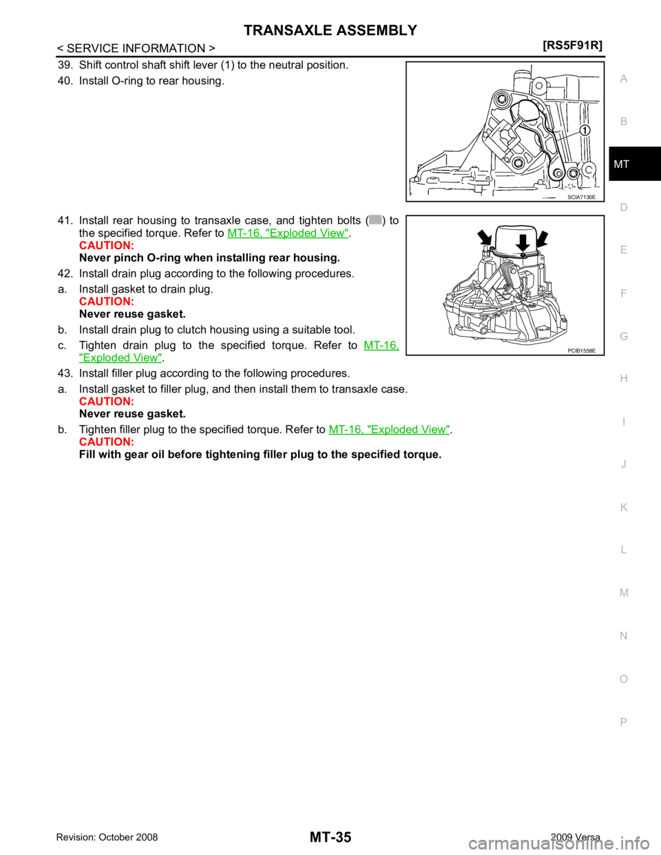
39. Shift control shaft shift lever (1) to the neutral position.
40. Install O-ring to rear housing.
41. Install rear housing to transaxle case, and tighten bolts ( ) to the specified torque. Refer to MT-16, " Exploded View " .
CAUTION:
Never pinch O-ring when installing rear housing.
42. Install drain plug according to the following procedures.
a. Install gasket to drain plug. CAUTION:
Never reuse gasket.
b. Install drain plug to clutch housing using a suitable tool.
c. Tighten drain plug to the specified torque. Refer to MT-16," Exploded View " .
43. Install filler plug according to the following procedures.
a. Install gasket to filler plug, and then install them to transaxle case. CAUTION:
Never reuse gasket.
b. Tighten filler plug to the specified torque. Refer to MT-16, " Exploded View " .
CAUTION:
Fill with gear oil before tightening filler plug to the specified torque.
Page 3830 of 4331
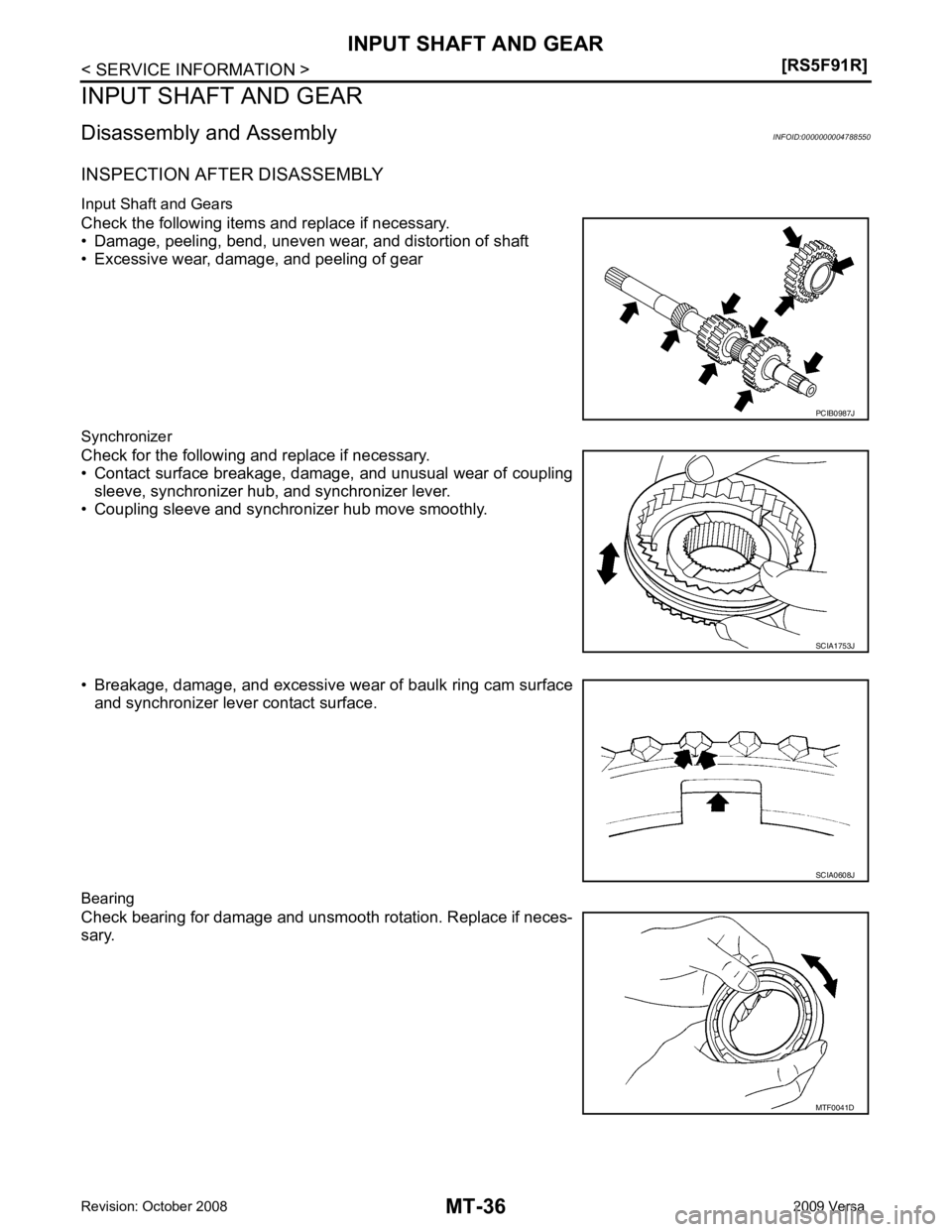
SCIA1753J
MTF0041D