NISSAN X-TRAIL 2001 Service Repair Manual
Manufacturer: NISSAN, Model Year: 2001, Model line: X-TRAIL, Model: NISSAN X-TRAIL 2001Pages: 3833, PDF Size: 39.49 MB
Page 2611 of 3833
TF-1
TRANSFER
D DRIVELINE/AXLE
CONTENTS
C
E
F
G
H
I
J
K
L
M
SECTION
A
B
TF
TRANSFER
PRECAUTIONS .......................................................... 3
Caution ..................................................................... 3
PREPARATION ........................................................... 4
Special Service Tools ............................................... 4
NOISE, VIBRATION, AND HARSHNESS (NVH)
TROUBLESHOOTING ................................................ 7
NVH Troubleshooting Chart ..................................... 7
TRANSFER FLUID ..................................................... 8
Replacement ............................................................ 8
DRAINING ............................................................. 8
FILLING ................................................................. 8
Inspection ................................................................. 8
OIL LEAKAGE AND OIL LEVEL ........................... 8
SIDE OIL SEAL .......................................................... 9
Removal and Installation .......................................... 9
REMOVAL ............................................................. 9
INSTALLATION ..................................................... 9
AIR BREATHER HOSE ............................................ 10
Removal and Installation ........................................ 10
TRANSFER ASSEMBLY ...........................................11
Removal and Installation from Vehicle .................... 11
REMOVAL ............................................................ 11
INSTALLATION .................................................... 11
Component Parts Drawing ..................................... 13
Assembly Inspection .............................................. 14
BACKLASH ......................................................... 14
TOOTH CONTACT .............................................. 14
PRELOAD TORQUE ........................................... 16
COMPANION FLANGE RUNOUT ...................... 17
Disassembly and Assembly ................................... 18
DISASSEMBLY ................................................... 18
INSPECTION AFTER DISASSEMBLY ............... 22
SELECTIONG ADJUSTING SHIMS ................... 23
ASSEMBLY ......................................................... 24
ALL MODE 4X4 SYSTEM ........................................ 30
Precautions ............................................................ 30
System Component ................................................ 30
System Description ................................................ 30
ELECTRONIC COUPLING ................................. 30
4WD CONTROL UNIT ........................................ 304WD MODE SWITCH ......................................... 31
4WD WARNING LAMP ....................................... 31
FAIL- SAFE FUNCTION ...................................... 32
System Diagram ..................................................... 32
CAN Communication ...........................................
... 32
SYSTEM DESCRIPTION .................................... 32
SYSTEM DIAGRAM ............................................ 32
INPUT/OUTPUT SIGNAL .................................... 33
Circuit Diagram ....................................................... 34
Wiring Diagram ....................................................... 35
TROUBLE DIAGNOSIS ............................................ 40
Fail-safe function .................................................... 40
How to proceed with trouble diagnosis ................... 40
BASIC CONCEPT ............................................... 40
Trouble diagnosis chart by symptom ...................... 41
4WD control unit input/output signal standard ........ 42
4WD CONTROL UNIT CONNECTOR TERMI-
NAL ARRANGEMENT ........................................ 42
REFERENCE STANDARD TABLE ...................... 43
CONSULT-II functions ............................................ 45
CONSULT-II FUNCTION APPLICATION TABLE ... 45
SELF-DIAGNOSIS .............................................. 45
DATA MONITOR ................................................. 46
ACTIVE TEST ..................................................... 48
ECU PART NUMBER .......................................... 49
Component Inspection ............................................ 49
4WD SOLENOID VALVE ..................................... 49
System Inspection .................................................. 49
CONTROL UNIT POWER SUPPLY SYSTEM .... 49
G-SENSOR SYSTEM ......................................... 50
4WD SOLENOID, ACTUATOR RELAY SYSTEM ... 52
CAN COMMUNICATION SYSTEM ..................... 53
4WD MODE SWITCH SYSTEM .......................... 54
Trouble Diagnoses for Symptoms .......................... 55
4WD INDICATOR LAMP DOSE NOT COME ON
FOR APPROXIMATELY 1 SECOND WHEN THE
IGNITION SWITCH IS TURNED TO ON ............. 55
4WD WARNING LAMP DOES NOT ILLUMINATE
WITH IGNITION ON ............................................ 55
4WD WARNING LAMP DOES NOT GO OUT
Page 2612 of 3833
TF-2
SEVERAL SECONDS AFTER ENGINE
STARTED.(4WD MODE INDICATOR LAMP
GOES OUT) ........................................................ 56
HEAVY TIGHT-CORNER BRAKING SYMPTOM
OCCURS WHEN THE VEHICLE IS DRIVEN IN
AUTO MODE AND THE STEERING WHEEL IS
TURNED FULLY TO EITHER SIDE AFTER THE
ENGINE IS STARTED ......................................... 56
4WD MODES CANNOT BE SWITCHED AFTER
ENGINE IS STARTED ......................................... 57
WHILE DRIVING, 4WD WARNING LAMP
FLASHES RAPIDLY. (WHEN IT FLASHERS FOR
APPROX. ONE MINUTE, THEN DOES NOT
ILLUMINATE.) ..................................................... 57
WHILE DRIVING, 4WD WARNING LAMP
FLASHES SLOWLY. (WHEN IT CONTINUES TO
ILLUMINATE UNTIL ENGINE TURNS OFF.) ...... 57
VEHICLE DOES NOT ENTER 4WD MODE EVEN THOUGH 4WD WARNING LAMP IS OFF. ... 58
TIGHT-CONER BRAKING SYMPTOM OCCURS
WHEN THE VEHICLE IS STARTED IN AUTO
WARNING LAMP REMAIN OFF). ....................... 58
4WD ACTUATOR RELAY (4WD SOLENOID
ACTUATOR RELAY) TURNS ON/OFF FRE-
QUENTLY ............................................................ 58
SERVICE DATA AND SPECIFICATIONS (SDS) ...... 59
General Specifications ......................................... ... 59
Inspection and Adjustment ...................................... 59
PRELOAD TORQUE BEFORE DISASSEMBLY ... 59
PRELOAD TORQUE AFTER DISASSEMBLY
AND REASSEMBLY ............................................ 59
BACKLSH ............................................................ 59
COMPANION FLANGE RUNOUT ....................... 59
SELECTIVE PARTS ............................................ 59
PINION SLEEVE SHIM ........................................ 60
Page 2613 of 3833
PRECAUTIONS
TF-3
C
E
F
G
H
I
J
K
L
MA
B
TF
PRECAUTIONSPFP:00001
CautionEDS0004O
●Do not reuse the drained transfer oil.
●Check the oil level with the vehicle on the level ground.
●During removal and installation, be careful not to allow foreign material such as dust or dirt to enter into
the transfer unit.
●Before starting diagnosis of the vehicle, understand trouble symptoms well. Perform correct and system-
atic operations.
●Check for the correct installation status prior to removal or disassembly. If mating marks are required, be
certain they do not interfere with the function of the parts they are applied to.
●Carry out the work in a clean work place. Using a dust proof room is recommended.
●Before disassembly, using steam or white gasoline, completely remove sand and mud from the exterior of
the unit, preventing them from entering into the unit during disassembly or assembly.
●Check appearance of the disassembled parts for damage, deformation, and abnormal wear. If a malfunc-
tion is detected, replace it with a new one.
●Normally replace O-rings, oil seals, bearings, and lock nuts with new ones every time they are removed.
●In principle, tighten bolts or nuts gradually in several steps working diagonally from inside to outside. If
tightening sequence is specified, observe it.
●Clean and flush the parts sufficiently and blow them dry.
●Be careful not to damage sliding surfaces and mating surfaces.
●Always use shop paper for cleaning the inside of components.
●Do not use cotton gloves or a shop cloth. Using them may leave lint on the surface of the parts.
●During assembly always tighten bolts and screws to specified torque. New transfer oil a petroleum jelly
such as "Vaseline", or multi-purpose grease as appropriate.
●Discard waste oil after oil changes or part treatment in accordance with local laws and regulations.
Page 2614 of 3833
TF-4
PREPARATION
PREPARATION
PFP:00002
Special Service ToolsEDS0004P
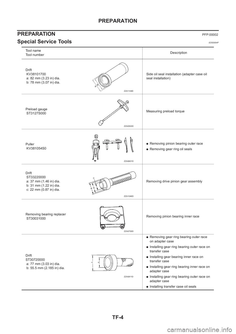
Tool name
Tool numberDescription
Drift
KV38101700
a: 82 mm (3.23 in) dia.
b: 78 mm (3.07 in) dia.Side oil seal installation (adapter case oil
seal installation)
Preload gauge
ST3127S000Measuring preload torque
Puller
KV381054S0
●Removing pinion bearing outer race
●Removing gear ring oil seals
Drift
ST33220000
a: 37 mm (1.46 in) dia.
b: 31 mm (1.22 in) dia.
c: 22 mm (0.87 in) dia.Removing drive pinion gear assembly
Removing bearing replacer
ST30031000Removing pinion bearing inner race
Drift
ST30720000
a: 77 mm (3.03 in) dia.
b: 55.5 mm (2.185 in) dia.
●Removing gear ring bearing outer race
on adapter case
●Installing gear ring bearing outer race on
transfer case
●Installing gear bearing inner race on
transfer case
●Installing gear ring bearing inner race on
adapter case
●Installing gear ring bearing outer race on
adapter case
●Installing transfer case oil seals
ZZA1149D
ZZA0503D
ZZA0601D
ZZA1046D
ZZA0700D
ZZA0811D
Page 2615 of 3833
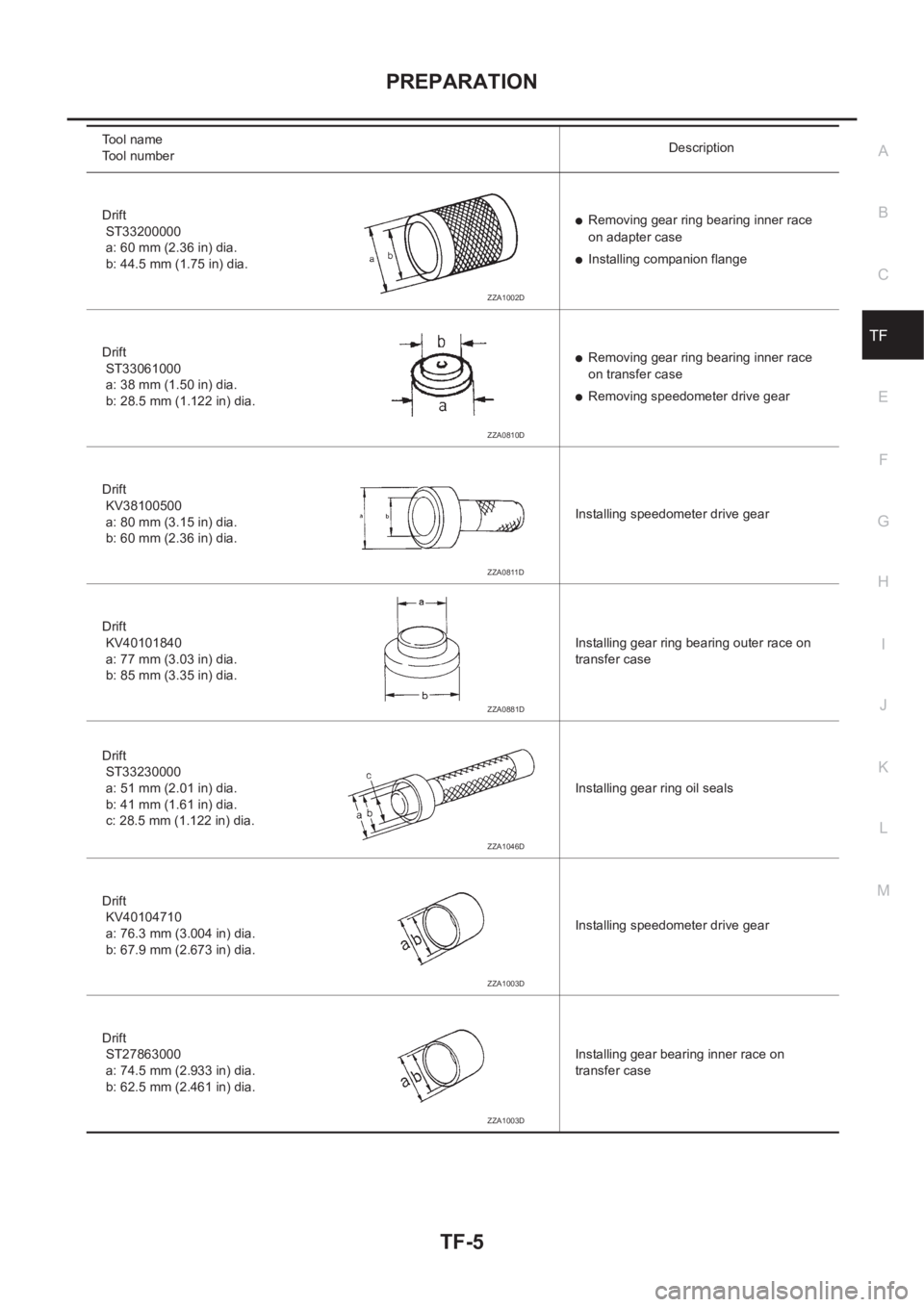
PREPARATION
TF-5
C
E
F
G
H
I
J
K
L
MA
B
TF
Drift
ST33200000
a: 60 mm (2.36 in) dia.
b: 44.5 mm (1.75 in) dia.●Removing gear ring bearing inner race
on adapter case
●Installing companion flange
Drift
ST33061000
a: 38 mm (1.50 in) dia.
b: 28.5 mm (1.122 in) dia.
●Removing gear ring bearing inner race
on transfer case
●Removing speedometer drive gear
Drift
KV38100500
a: 80 mm (3.15 in) dia.
b: 60 mm (2.36 in) dia.Installing speedometer drive gear
Drift
KV40101840
a: 77 mm (3.03 in) dia.
b: 85 mm (3.35 in) dia.Installing gear ring bearing outer race on
transfer case
Drift
ST33230000
a: 51 mm (2.01 in) dia.
b: 41 mm (1.61 in) dia.
c: 28.5 mm (1.122 in) dia.Installing gear ring oil seals
Drift
KV40104710
a: 76.3 mm (3.004 in) dia.
b: 67.9 mm (2.673 in) dia.Installing speedometer drive gear
Drift
ST27863000
a: 74.5 mm (2.933 in) dia.
b: 62.5 mm (2.461 in) dia.Installing gear bearing inner race on
transfer case Tool name
Tool numberDescription
ZZA1002D
ZZA0810D
ZZA0811D
ZZA0881D
ZZA1046D
ZZA1003D
ZZA1003D
Page 2616 of 3833
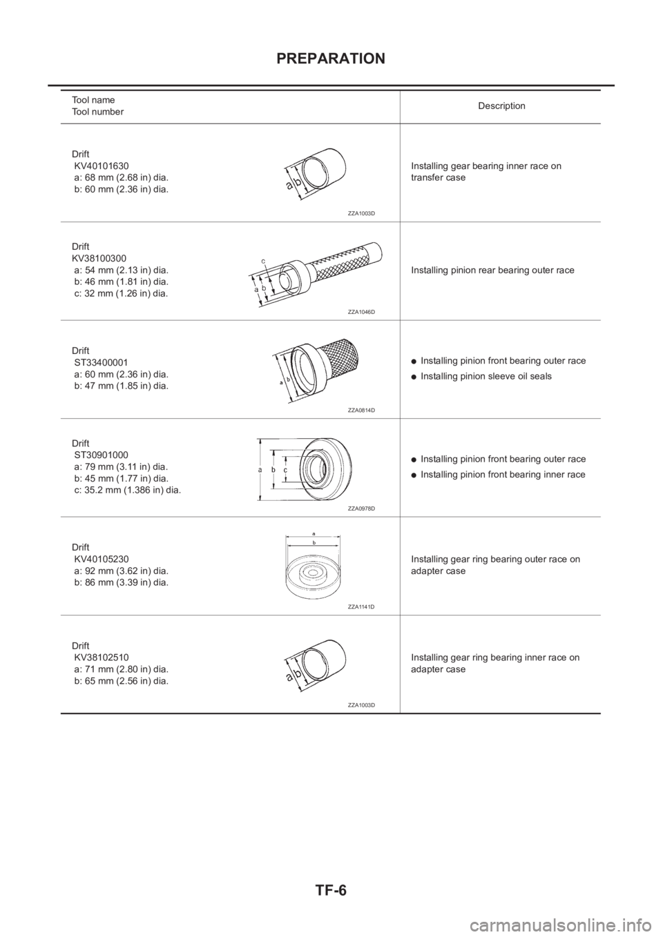
TF-6
PREPARATION
Drift
KV40101630
a: 68 mm (2.68 in) dia.
b: 60 mm (2.36 in) dia.Installing gear bearing inner race on
transfer case
Drift
KV38100300
a: 54 mm (2.13 in) dia.
b: 46 mm (1.81 in) dia.
c: 32 mm (1.26 in) dia.Installing pinion rear bearing outer race
Drift
ST33400001
a: 60 mm (2.36 in) dia.
b: 47 mm (1.85 in) dia.
●Installing pinion front bearing outer race
●Installing pinion sleeve oil seals
Drift
ST30901000
a: 79 mm (3.11 in) dia.
b: 45 mm (1.77 in) dia.
c: 35.2 mm (1.386 in) dia.
●Installing pinion front bearing outer race
●Installing pinion front bearing inner race
Drift
KV40105230
a: 92 mm (3.62 in) dia.
b: 86 mm (3.39 in) dia.Installing gear ring bearing outer race on
adapter case
Drift
KV38102510
a: 71 mm (2.80 in) dia.
b: 65 mm (2.56 in) dia.Installing gear ring bearing inner race on
adapter case Tool name
Tool numberDescription
ZZA1003D
ZZA1046D
ZZA0814D
ZZA0978D
ZZA1141D
ZZA1003D
Page 2617 of 3833
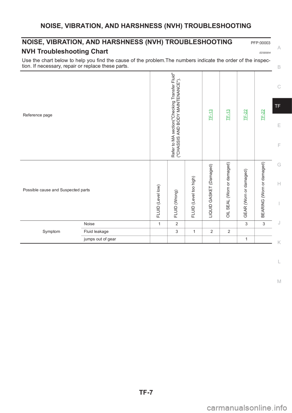
NOISE, VIBRATION, AND HARSHNESS (NVH) TROUBLESHOOTING
TF-7
C
E
F
G
H
I
J
K
L
MA
B
TF
NOISE, VIBRATION, AND HARSHNESS (NVH) TROUBLESHOOTINGPFP:00003
NVH Troubleshooting ChartEDS000I4
Use the chart below to help you find the cause of the problem.The numbers indicate the order of the inspec-
tion. If necessary, repair or replace these parts.
Reference page
Refer to MA section("Checking Transfer Fluid"
("CHASSIS AND BODY MAINTENANCE").
TF-13
TF-13TF-22TF-22
Possible cause and Suspected parts
FLUID (Level low)
FLUID (Wrong)
FLUID (Level too high)
LIQUID GASKET (Damaged)
OIL SEAL (Worn or damaged)
GEAR (Worn or damaged)
BEARING (Worn or damaged)
SymptomNoise 1 2 3 3
Fluid leakage 3 1 2 2
jumps out of gear 1
Page 2618 of 3833
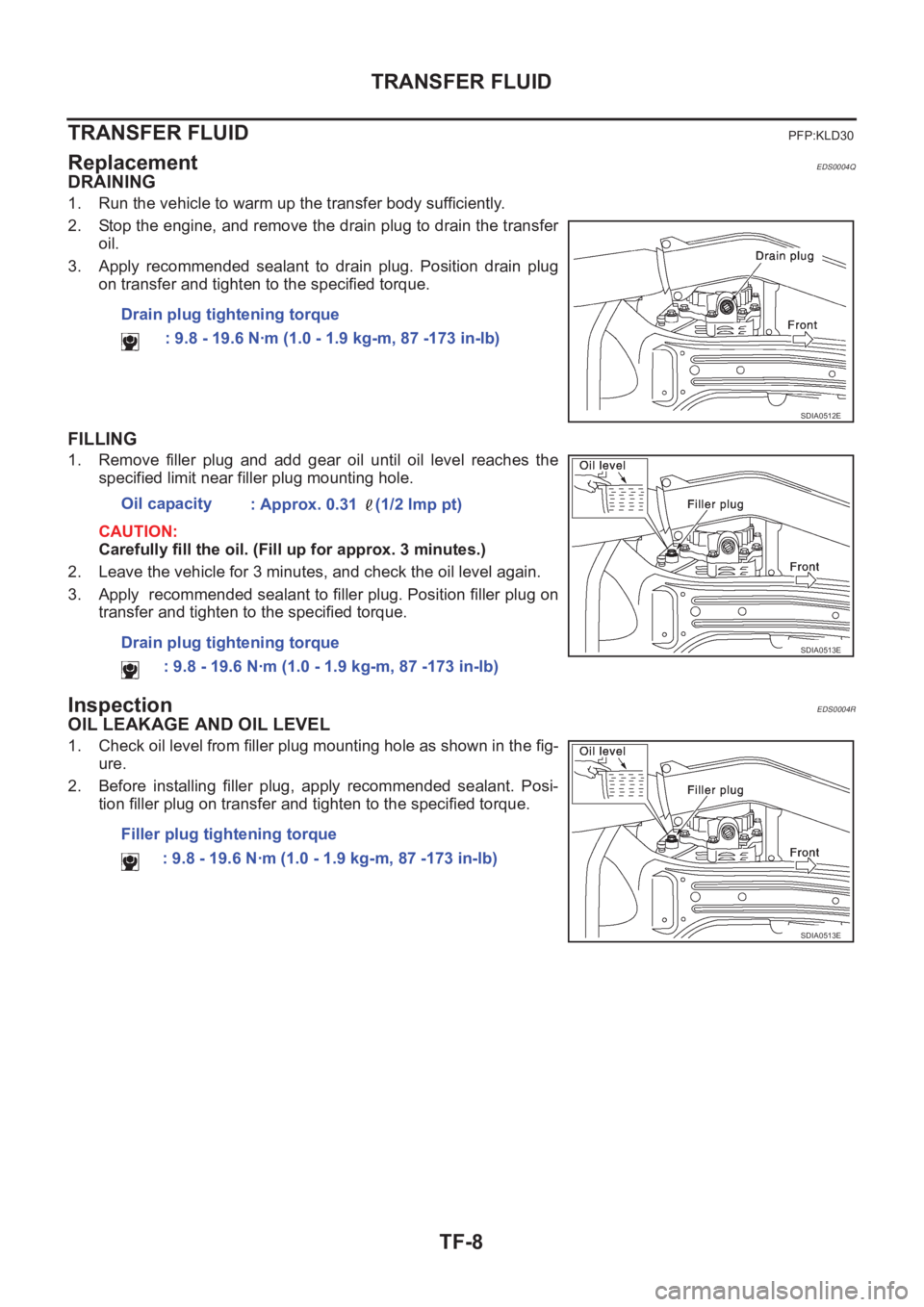
TF-8
TRANSFER FLUID
TRANSFER FLUID
PFP:KLD30
ReplacementEDS0004Q
DRAINING
1. Run the vehicle to warm up the transfer body sufficiently.
2. Stop the engine, and remove the drain plug to drain the transfer
oil.
3. Apply recommended sealant to drain plug. Position drain plug
on transfer and tighten to the specified torque.
FILLING
1. Remove filler plug and add gear oil until oil level reaches the
specified limit near filler plug mounting hole.
CAUTION:
Carefully fill the oil. (Fill up for approx. 3 minutes.)
2. Leave the vehicle for 3 minutes, and check the oil level again.
3. Apply recommended sealant to filler plug. Position filler plug on
transfer and tighten to the specified torque.
InspectionEDS0004R
OIL LEAKAGE AND OIL LEVEL
1. Check oil level from filler plug mounting hole as shown in the fig-
ure.
2. Before installing filler plug, apply recommended sealant. Posi-
tion filler plug on transfer and tighten to the specified torque. Drain plug tightening torque
: 9.8 - 19.6 N·m (1.0 - 1.9 kg-m, 87 -173 in-lb)
SDIA0512E
Oil capacity
: Approx. 0.31 (1/2 lmp pt)
Drain plug tightening torque
: 9.8 - 19.6 N·m (1.0 - 1.9 kg-m, 87 -173 in-lb)
SDIA0513E
Filler plug tightening torque
: 9.8 - 19.6 N·m (1.0 - 1.9 kg-m, 87 -173 in-lb)
SDIA0513E
Page 2619 of 3833
SIDE OIL SEAL
TF-9
C
E
F
G
H
I
J
K
L
MA
B
TF
SIDE OIL SEALPFP:33142
Removal and InstallationEDS0004S
REMOVAL
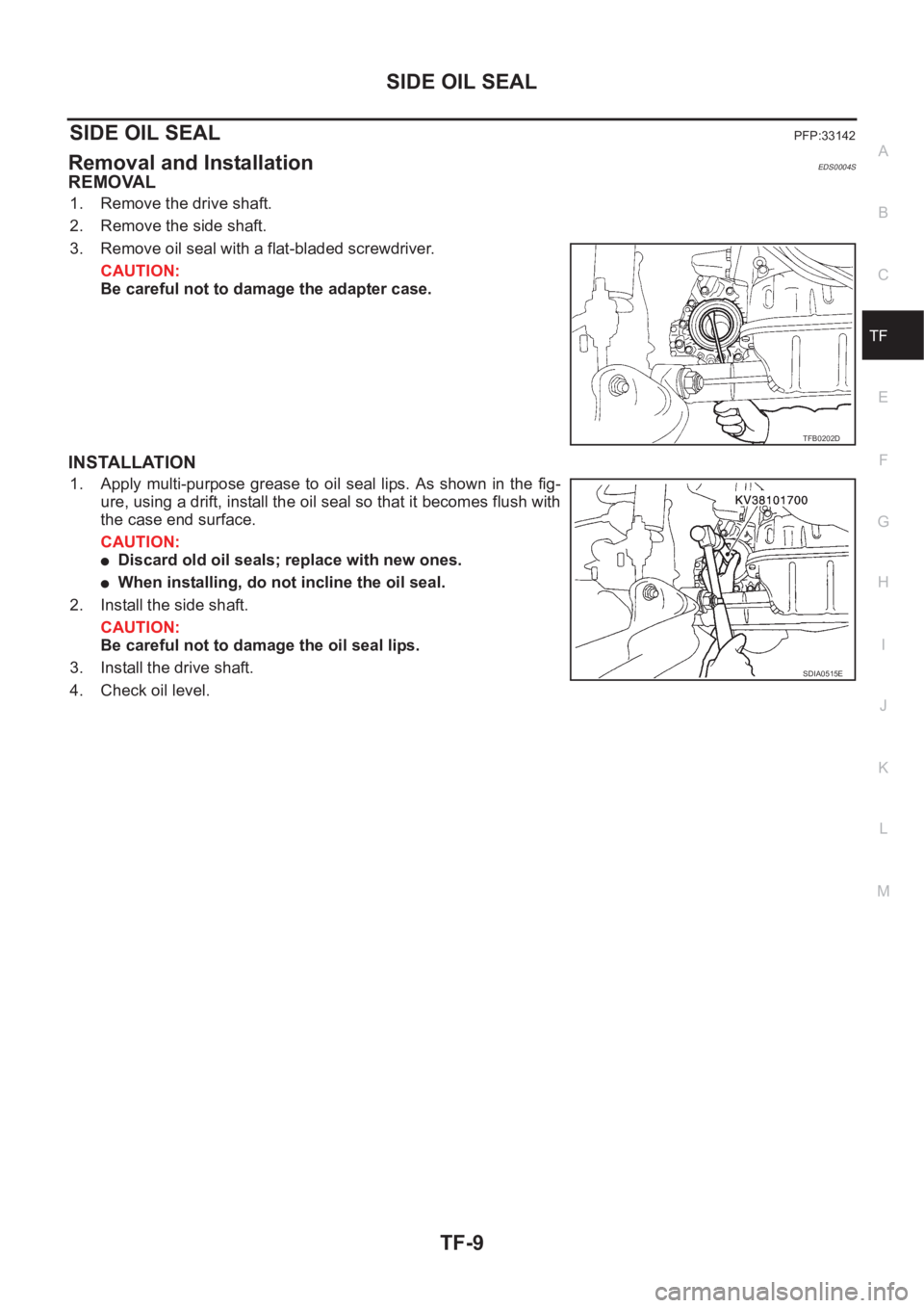
1. Remove the drive shaft.
2. Remove the side shaft.
3. Remove oil seal with a flat-bladed screwdriver.
CAUTION:
Be careful not to damage the adapter case.
INSTALLATION
1. Apply multi-purpose grease to oil seal lips. As shown in the fig-
ure, using a drift, install the oil seal so that it becomes flush with
the case end surface.
CAUTION:
●Discard old oil seals; replace with new ones.
●When installing, do not incline the oil seal.
2. Install the side shaft.
CAUTION:
Be careful not to damage the oil seal lips.
3. Install the drive shaft.
4. Check oil level.
TFB0202D
SDIA0515E
Page 2620 of 3833
TF-10
AIR BREATHER HOSE
AIR BREATHER HOSE
PFP:31098
Removal and InstallationEDS0004T
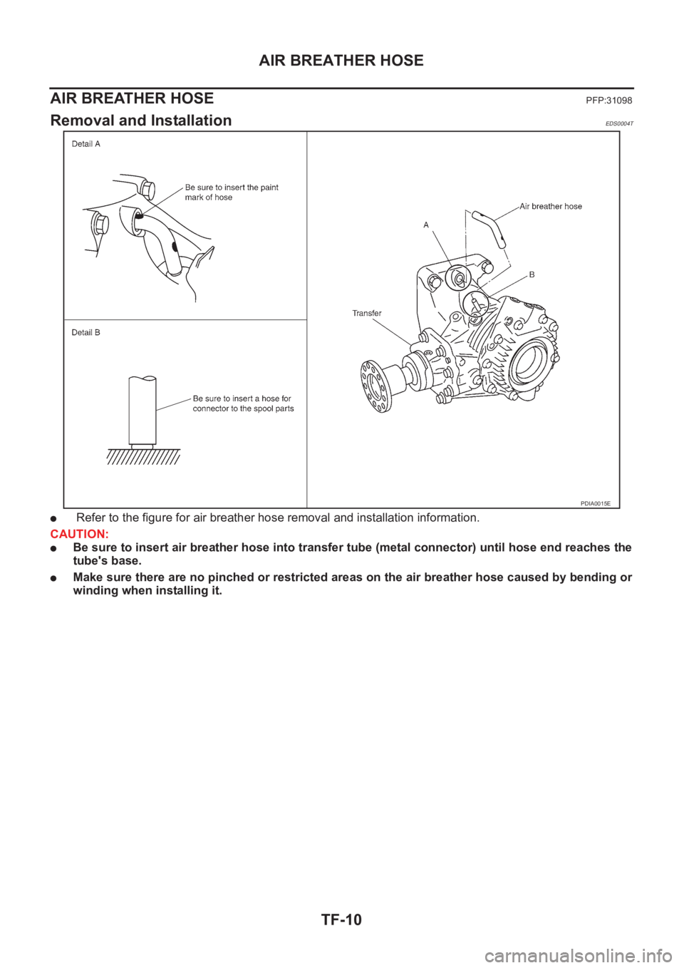
● Refer to the figure for air breather hose removal and installation information.
CAUTION:
●Be sure to insert air breather hose into transfer tube (metal connector) until hose end reaches the
tube's base.
●Make sure there are no pinched or restricted areas on the air breather hose caused by bending or
winding when installing it.
PDIA0015E