NISSAN X-TRAIL 2001 Service Repair Manual
X-TRAIL 2001
NISSAN
NISSAN
https://www.carmanualsonline.info/img/5/57405/w960_57405-0.png
NISSAN X-TRAIL 2001 Service Repair Manual
Trending: jack points, fuse, oil level, ec-478, overheating, Di-10, turn signal
Page 3391 of 3833
INTAKE SENSOR CIRCUIT
ATC-115
C
D
E
F
G
H
I
K
L
MA
B
AT C
INTAKE SENSOR CIRCUITPFP:27723
Removal and InstallationEJS000UK
1. Remove the evaporator. Refer to ATC-145, "Removal and Instal-
lation for Evaporator"
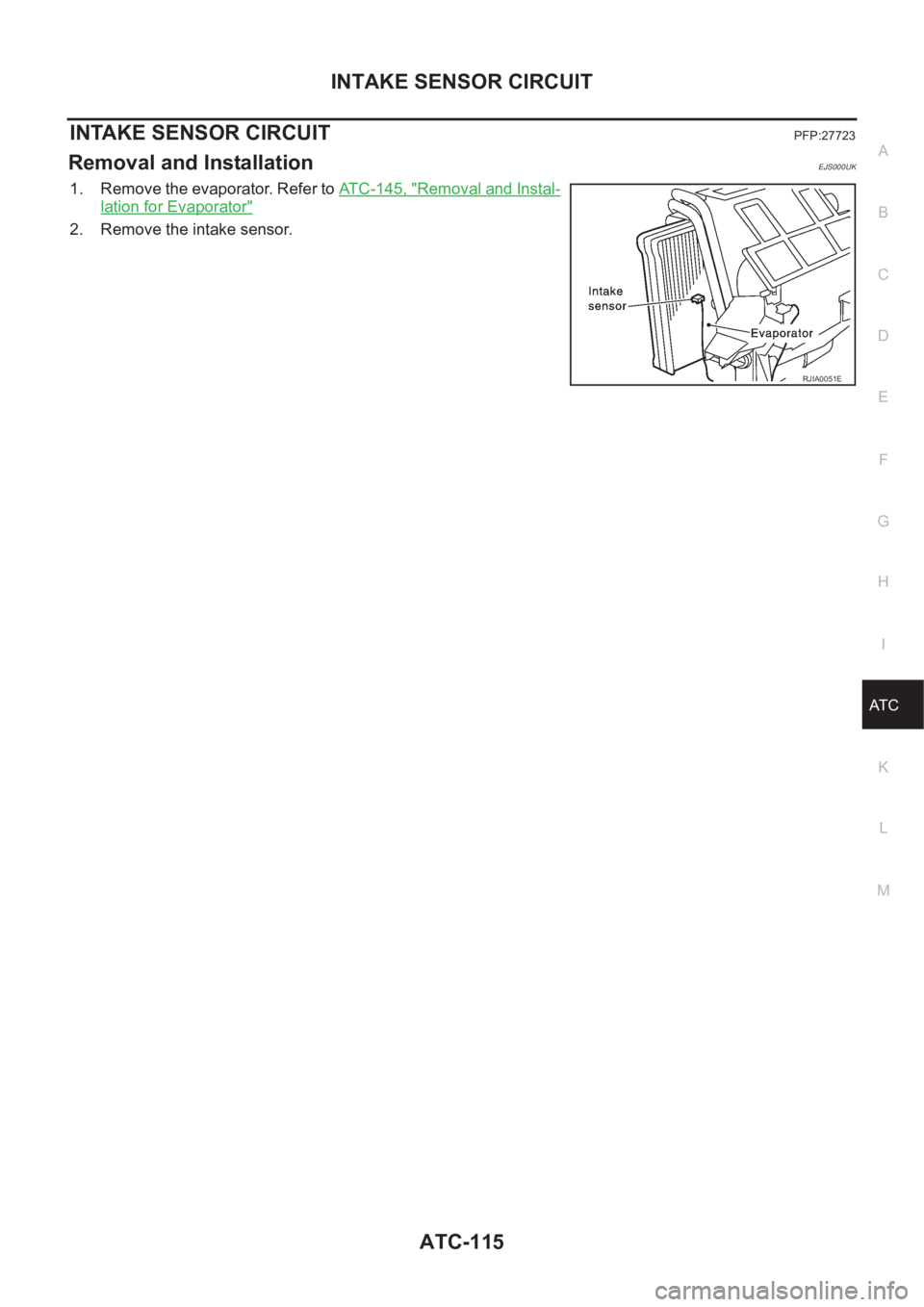
2. Remove the intake sensor.
RJIA0051E
Page 3392 of 3833
ATC-116
BLOWER UNIT
BLOWER UNIT
PFP:27200
Removal and InstallationEJS000UL
REMOVAL
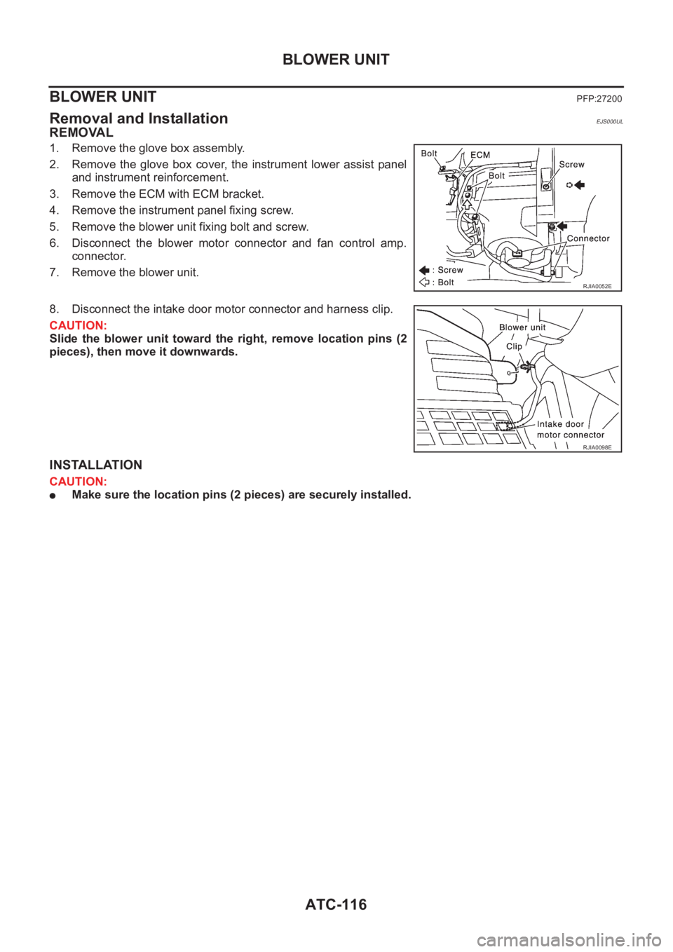
1. Remove the glove box assembly.
2. Remove the glove box cover, the instrument lower assist panel
and instrument reinforcement.
3. Remove the ECM with ECM bracket.
4. Remove the instrument panel fixing screw.
5. Remove the blower unit fixing bolt and screw.
6. Disconnect the blower motor connector and fan control amp.
connector.
7. Remove the blower unit.
8. Disconnect the intake door motor connector and harness clip.
CAUTION:
Slide the blower unit toward the right, remove location pins (2
pieces), then move it downwards.
INSTALLATION
CAUTION:
●Make sure the location pins (2 pieces) are securely installed.
RJIA0052E
RJIA0098E
Page 3393 of 3833
BLOWER UNIT
ATC-117
C
D
E
F
G
H
I
K
L
MA
B
AT C
Disassembly and AssemblyEJS000UM
NOTE:
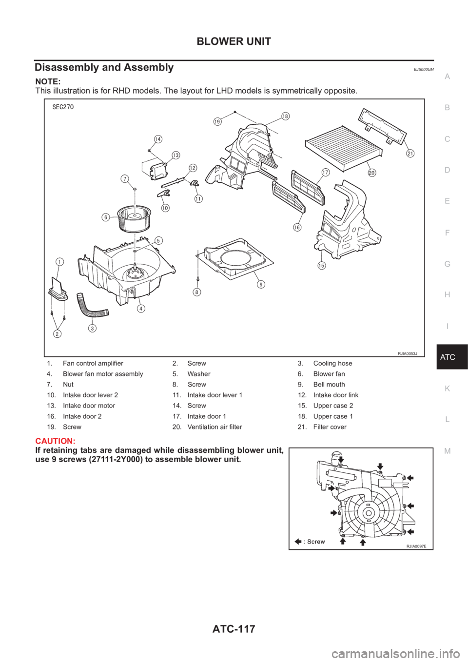
This illustration is for RHD models. The layout for LHD models is symmetrically opposite.
CAUTION:
If retaining tabs are damaged while disassembling blower unit,
use 9 screws (27111-2Y000) to assemble blower unit.
1. Fan control amplifier 2. Screw 3. Cooling hose
4. Blower fan motor assembly 5. Washer 6. Blower fan
7. Nut 8. Screw 9. Bell mouth
10. Intake door lever 2 11. Intake door lever 1 12. Intake door link
13. Intake door motor 14. Screw 15. Upper case 2
16. Intake door 2 17. Intake door 1 18. Upper case 1
19. Screw 20. Ventilation air filter 21. Filter cover
RJIA0053J
RJIA0097E
Page 3394 of 3833
ATC-118
BLOWER MOTOR
BLOWER MOTOR
PFP:27226
Removal and InstallationEJS000UN
1. Remove the blower unit. Refer to AT C - 11 6 , "Removal and Instal-
lation"
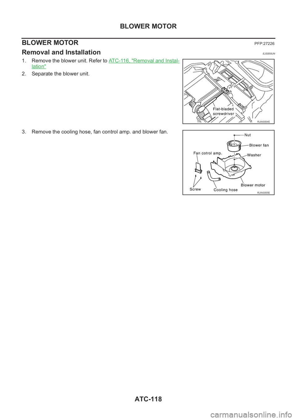
2. Separate the blower unit.
3. Remove the cooling hose, fan control amp. and blower fan.
RJIA0054E
RJIA0055E
Page 3395 of 3833
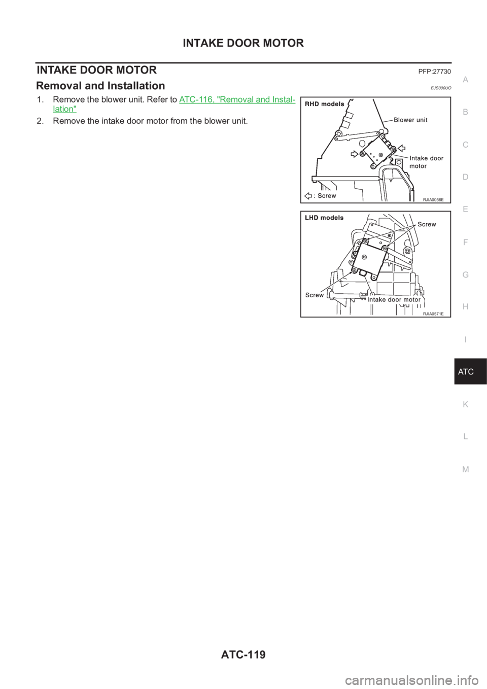
INTAKE DOOR MOTOR
ATC-119
C
D
E
F
G
H
I
K
L
MA
B
AT C
INTAKE DOOR MOTORPFP:27730
Removal and InstallationEJS000UO
1. Remove the blower unit. Refer to AT C - 11 6 , "Removal and Instal-
lation"
2. Remove the intake door motor from the blower unit.
RJIA0056E
RJIA0571E
Page 3396 of 3833
ATC-120
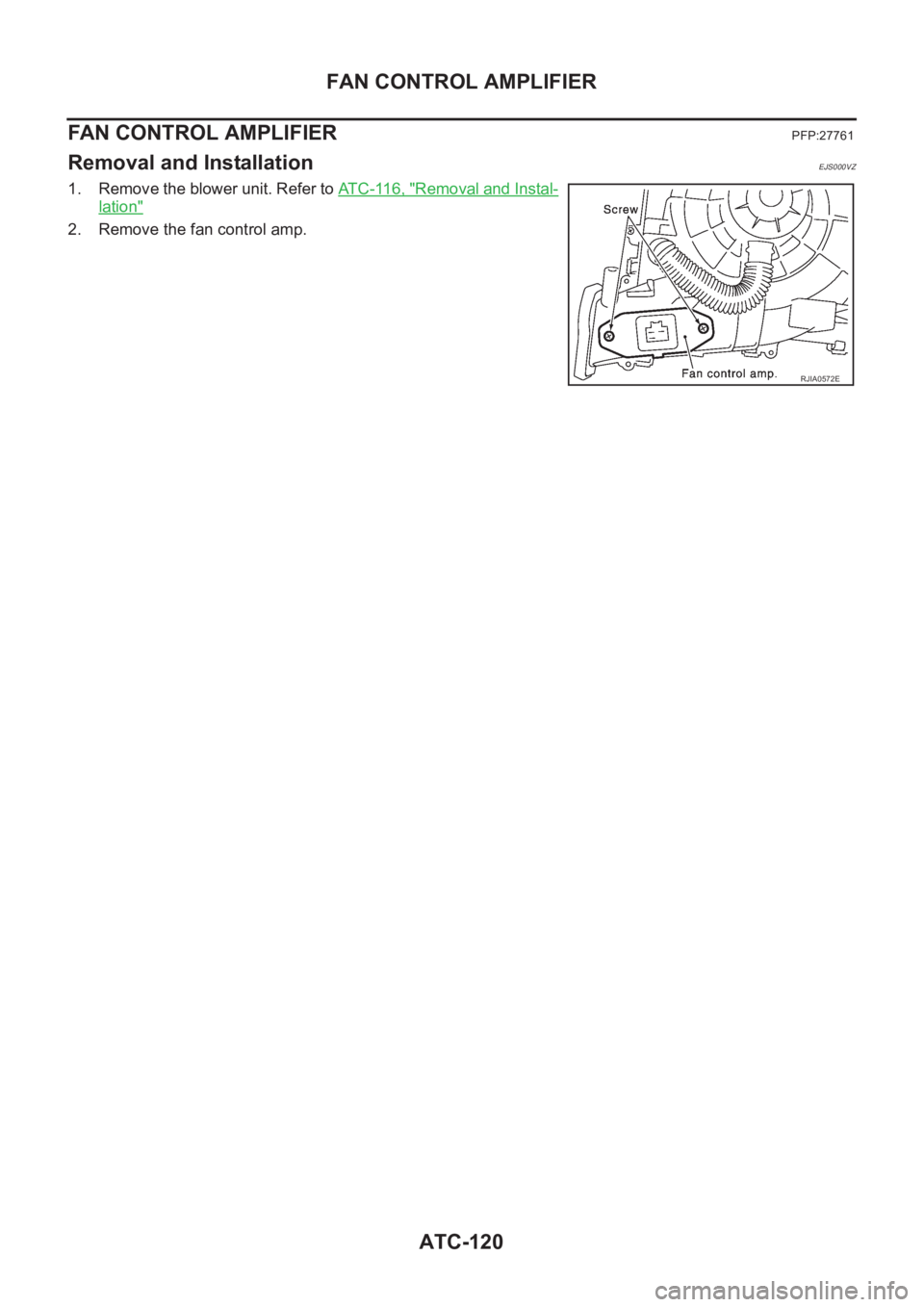
FAN CONTROL AMPLIFIER
FAN CONTROL AMPLIFIER
PFP:27761
Removal and InstallationEJS000VZ
1. Remove the blower unit. Refer to AT C - 11 6 , "Removal and Instal-
lation"
2. Remove the fan control amp.
RJIA0572E
Page 3397 of 3833
VENTILATION AIR FILTER
ATC-121
C
D
E
F
G
H
I
K
L
MA
B
AT C
VENTILATION AIR FILTER PFP:27277
Removal and InstallationEJS000UP
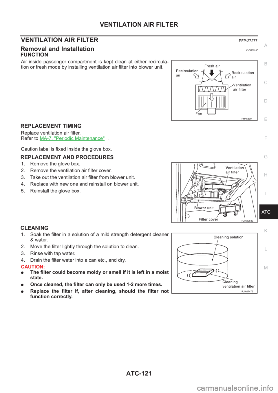
FUNCTION
Air inside passenger compartment is kept clean at either recircula-
tion or fresh mode by installing ventilation air filter into blower unit.
REPLACEMENT TIMING
Replace ventilation air filter.
Refer to MA-7, "
Periodic Maintenance" .
Caution label is fixed inside the glove box.
REPLACEMENT AND PROCEDURES
1. Remove the glove box.
2. Remove the ventilation air filter cover.
3. Take out the ventilation air filter from blower unit.
4. Replace with new one and reinstall on blower unit.
5. Reinstall the glove box.
CLEANING
1. Soak the filter in a solution of a mild strength detergent cleaner
& water.
2. Move the filter lightly through the solution to clean.
3. Rinse with tap water.
4. Drain the filter water into a can etc., and dry.
CAUTION:
●The filter could become moldy or smell if it is left in a moist
state.
●Once cleaned, the filter can only be used 1-2 more times.
●Replace the filter if, after cleaning, should the filter not
function correctly.
RHA680H
RJIA0058E
RJIA0747E
Page 3398 of 3833
ATC-122
HEATER & COOLING UNIT ASSEMBLY
HEATER & COOLING UNIT ASSEMBLY
PFP:27110
Removal and InstallationEJS000UT
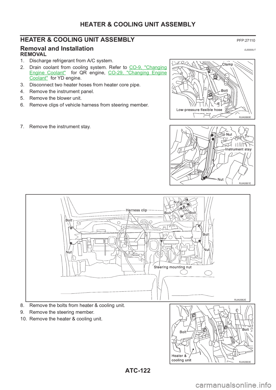
REMOVAL
1. Discharge refrigerant from A/C system.
2. Drain coolant from cooling system. Refer to CO-9, "
Changing
Engine Coolant" for QR engine, CO-29, "Changing Engine
Coolant" for YD engine.
3. Disconnect two heater hoses from heater core pipe.
4. Remove the instrument panel.
5. Remove the blower unit.
6. Remove clips of vehicle harness from steering member.
7. Remove the instrument stay.
8. Remove the bolts from heater & cooling unit.
9. Remove the steering member.
10. Remove the heater & cooling unit.
RJIA0060E
RJIA0061E
RJIA0062E
RJIA0063E
Page 3399 of 3833
HEATER & COOLING UNIT ASSEMBLY
ATC-123
C
D
E
F
G
H
I
K
L
MA
B
AT C
INSTALLATION
1. Installation is basically the reverse order of removal.
NOTE:
When filling radiator with coolant, refer to CO-9, "
Changing Engine Coolant" for QR engine, CO-29, "Chang-
ing Engine Coolant" for YD engine.
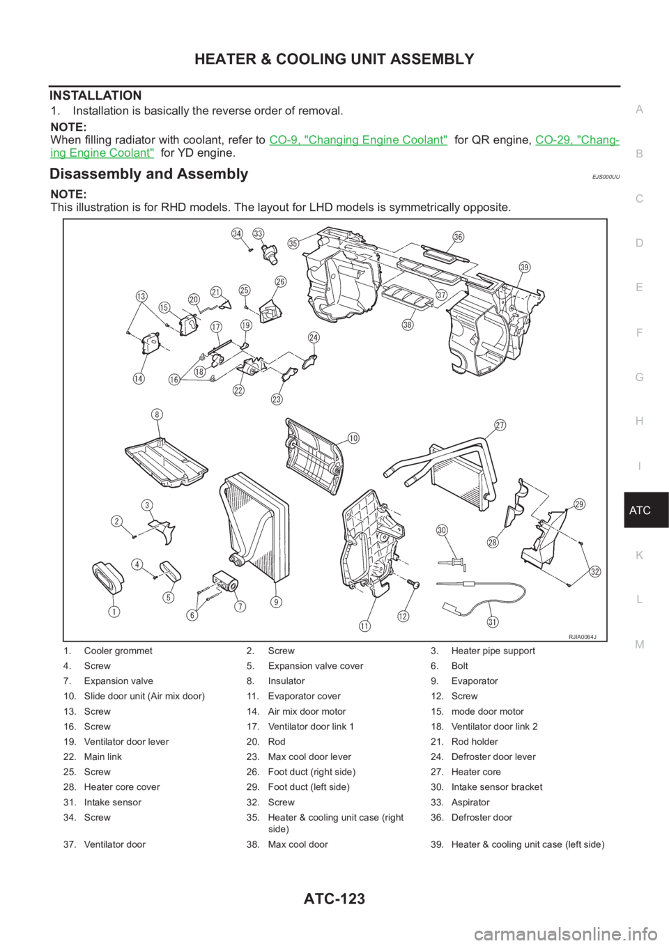
Disassembly and AssemblyEJS000UU
NOTE:
This illustration is for RHD models. The layout for LHD models is symmetrically opposite.
1. Cooler grommet 2. Screw 3. Heater pipe support
4. Screw 5. Expansion valve cover 6. Bolt
7. Expansion valve 8. Insulator 9. Evaporator
10. Slide door unit (Air mix door) 11. Evaporator cover 12. Screw
13. Screw 14. Air mix door motor 15. mode door motor
16. Screw 17. Ventilator door link 1 18. Ventilator door link 2
19. Ventilator door lever 20. Rod 21. Rod holder
22. Main link 23. Max cool door lever 24. Defroster door lever
25. Screw 26. Foot duct (right side) 27. Heater core
28. Heater core cover 29. Foot duct (left side) 30. Intake sensor bracket
31. Intake sensor 32. Screw 33. Aspirator
34. Screw 35. Heater & cooling unit case (right
side)36. Defroster door
37. Ventilator door 38. Max cool door 39. Heater & cooling unit case (left side)
RJIA0064J
Page 3400 of 3833
ATC-124
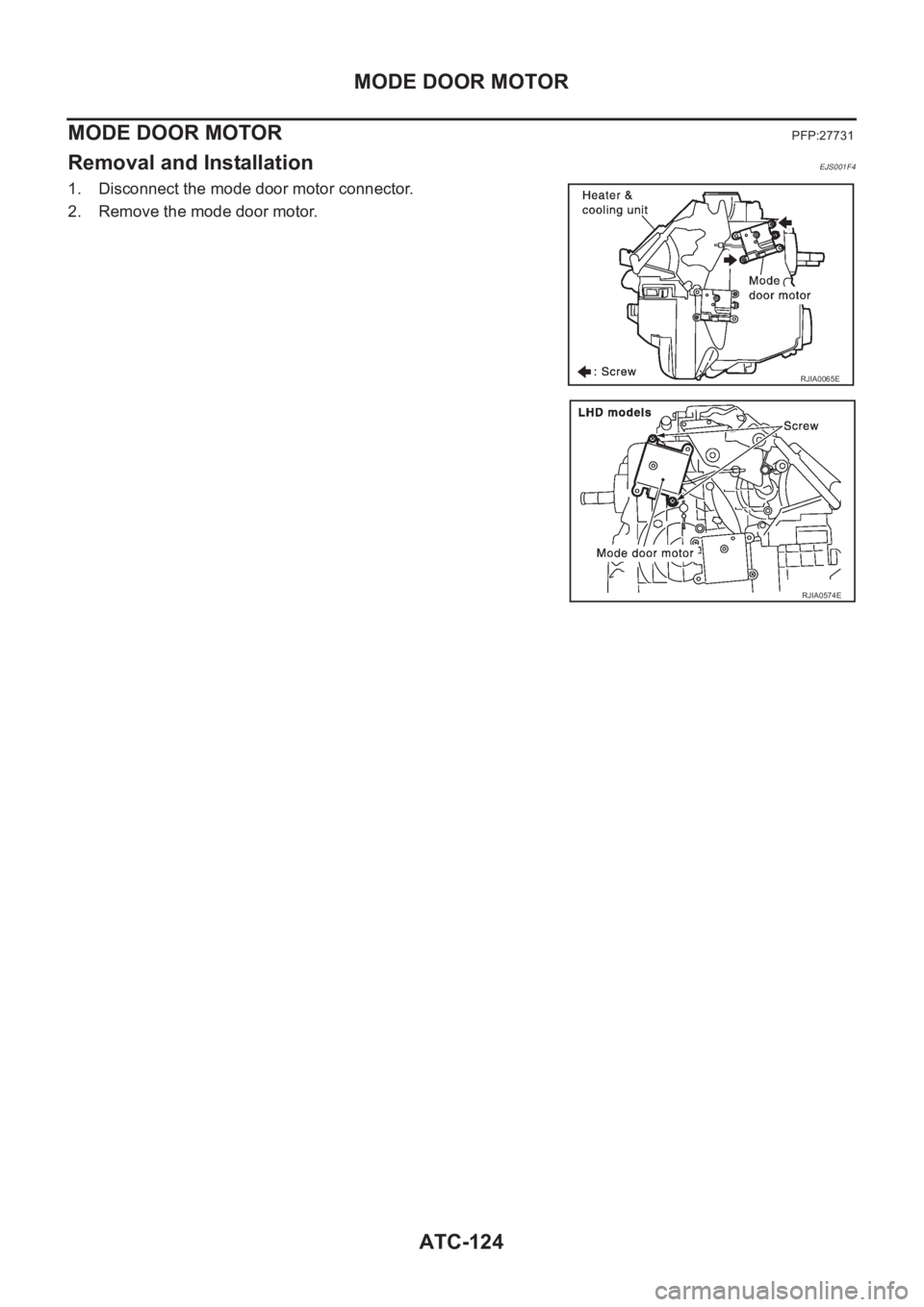
MODE DOOR MOTOR
MODE DOOR MOTOR
PFP:27731
Removal and InstallationEJS001F4
1. Disconnect the mode door motor connector.
2. Remove the mode door motor.
RJIA0065E
RJIA0574E
Trending: roof rack, oil temperature, Tf-31, center console, radiator, electrical cigarette lighter, octane
