NISSAN X-TRAIL 2001 Service Repair Manual
Manufacturer: NISSAN, Model Year: 2001, Model line: X-TRAIL, Model: NISSAN X-TRAIL 2001Pages: 3833, PDF Size: 39.49 MB
Page 361 of 3833
EC-11
C
D
E
F
G
H
I
J
K
L
M
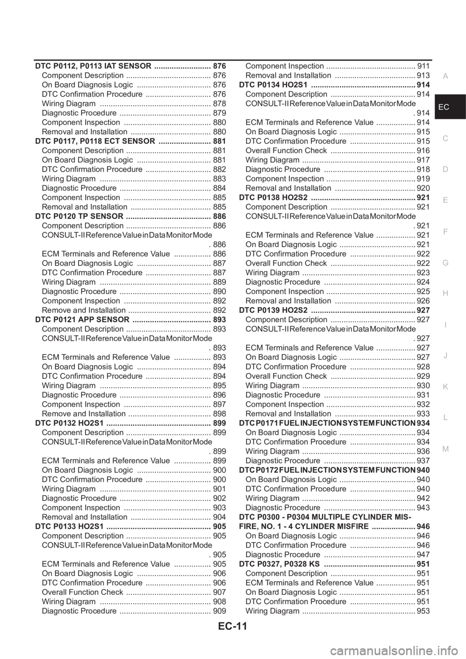
ECA DTC P0112, P0113 IAT SENSOR ........................... 876
Component Description ........................................ 876
On Board Diagnosis Logic ................................... 876
DTC Confirmation Procedure ............................... 876
Wiring Diagram .................................................... 878
Diagnostic Procedure ........................................... 879
Component Inspection ......................................... 880
Removal and Installation ...................................... 880
DTC P0117, P0118 ECT SENSOR ......................... 881
Component Description ........................................ 881
On Board Diagnosis Logic ................................... 881
DTC Confirmation Procedure ............................... 882
Wiring Diagram .................................................... 883
Diagnostic Procedure ........................................... 884
Component Inspection ......................................... 885
Removal and Installation ...................................... 885
DTC P0120 TP SENSOR ........................................ 886
Component Description ........................................ 886
CONSULT-II Reference Value in Data Monitor Mode
. 886
ECM Terminals and Reference Value .................. 886
On Board Diagnosis Logic ................................... 887
DTC Confirmation Procedure ............................... 887
Wiring Diagram .................................................... 889
Diagnostic Procedure ........................................... 890
Component Inspection ......................................... 892
Remove and Installation ....................................... 892
DTC P0121 APP SENSOR ..................................... 893
Component Description ........................................ 893
CONSULT-II Reference Value in Data Monitor Mode
. 893
ECM Terminals and Reference Value .................. 893
On Board Diagnosis Logic ................................... 894
DTC Confirmation Procedure ............................... 894
Wiring Diagram .................................................... 895
Diagnostic Procedure ........................................... 896
Component Inspection ......................................... 897
Remove and Installation ....................................... 898
DTC P0132 HO2S1 ................................................. 899
Component Description ........................................ 899
CONSULT-II Reference Value in Data Monitor Mode
. 899
ECM Terminals and Reference Value .................. 899
On Board Diagnosis Logic ................................... 900
DTC Confirmation Procedure ............................... 900
Wiring Diagram .................................................... 901
Diagnostic Procedure ........................................... 902
Component Inspection ......................................... 903
Removal and Installation ...................................... 904
DTC P0133 HO2S1 ...............................................
.. 905
Component Description ........................................ 905
CONSULT-II Reference Value in Data Monitor Mode
. 905
ECM Terminals and Reference Value .................. 905
On Board Diagnosis Logic ................................... 906
DTC Confirmation Procedure ............................... 906
Overall Function Check ........................................ 907
Wiring Diagram .................................................... 908
Diagnostic Procedure ........................................... 909Component Inspection ..........................................911
Removal and Installation ......................................913
DTC P0134 HO2S1 ................................................ .914
Component Description ........................................914
CONSULT-II Reference Value in Data Monitor Mode
.914
ECM Terminals and Reference Value ...................914
On Board Diagnosis Logic ....................................915
DTC Confirmation Procedure ...............................915
Overall Function Check ........................................916
Wiring Diagram .....................................................917
Diagnostic Procedure ...........................................918
Component Inspection ..........................................919
Removal and Installation ......................................920
DTC P0138 HO2S2 ................................................ .921
Component Description ........................................921
CONSULT-II Reference Value in Data Monitor Mode
.921
ECM Terminals and Reference Value ...................921
On Board Diagnosis Logic ....................................921
DTC Confirmation Procedure ...............................922
Overall Function Check ........................................922
Wiring Diagram .....................................................923
Diagnostic Procedure ...........................................924
Component Inspection ..........................................925
Removal and Installation ......................................926
DTC P0139 HO2S2 ................................................ .927
Component Description ........................................927
CONSULT-II Reference Value in Data Monitor Mode
.927
ECM Terminals and Reference Value ...................927
On Board Diagnosis Logic ....................................927
DTC Confirmation Procedure ...............................928
Overall Function Check ........................................929
Wiring Diagram .....................................................930
Diagnostic Procedure ...........................................931
Component Inspection ..........................................932
Removal and Installation ......................................933
DTC P0171 FUEL INJECTION SYSTEM FUNCTION .934
On Board Diagnosis Logic ....................................934
DTC Confirmation Procedure ...............................934
Wiring Diagram .....................................................936
Diagnostic Procedure ...........................................937
DTC P0172 FUEL INJECTION SYSTEM FUNCTION .940
On Board Diagnosis Logic ....................................940
DTC Confirmation Procedure ...............................940
Wiring Diagram .....................................................942
Diagnostic Procedure ...........................................943
DTC P0300 - P0304 MULTIPLE CYLINDER MIS-
FIRE, NO. 1 - 4 CYLINDER MISFIRE .....................946
On Board Diagnosis Logic ....................................946
DTC Confirmation Procedure ...............................946
Diagnostic Procedure ...........................................947
DTC P0327, P0328 KS ...........................................951
Component Description ........................................951
ECM Terminals and Reference Value ...................951
On Board Diagnosis Logic ....................................951
DTC Confirmation Procedure ...............................951
Wiring Diagram .....................................................953
Page 362 of 3833
EC-12
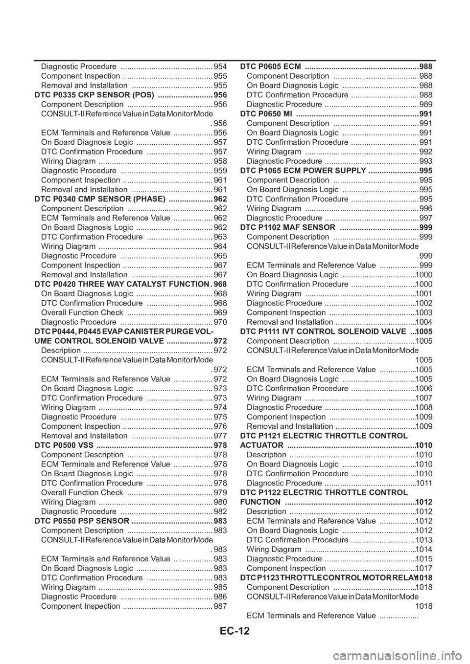
Diagnostic Procedure ...........................................954
Component Inspection ..........................................955
Removal and Installation ......................................955
DTC P0335 CKP SENSOR (POS) ..........................956
Component Description ........................................956
CONSULT-II Reference Value in Data Monitor Mode
.956
ECM Terminals and Reference Value ...................956
On Board Diagnosis Logic ....................................957
DTC Confirmation Procedure ...............................957
Wiring Diagram .....................................................958
Diagnostic Procedure ...........................................959
Component Inspection ..........................................961
Removal and Installation ......................................961
DTC P0340 CMP SENSOR (PHASE) .....................962
Component Description ........................................962
ECM Terminals and Reference Value ...................962
On Board Diagnosis Logic ....................................962
DTC Confirmation Procedure ...............................963
Wiring Diagram .....................................................964
Diagnostic Procedure ...........................................965
Component Inspection ..........................................967
Removal and Installation ......................................967
DTC P0420 THREE WAY CATALYST FUNCTION . 968
On Board Diagnosis Logic ....................................968
DTC Confirmation Procedure ...............................968
Overall Function Check ........................................969
Diagnostic Procedure ...........................................970
DTC P0444, P0445 EVAP CANISTER PURGE VOL-
UME CONTROL SOLENOID VALVE ......................972
Description ............................................................972
CONSULT-II Reference Value in Data Monitor Mode
.972
ECM Terminals and Reference Value ...................972
On Board Diagnosis Logic ....................................973
DTC Confirmation Procedure ...............................973
Wiring Diagram .....................................................974
Diagnostic Procedure ...........................................975
Component Inspection ..........................................976
Removal and Installation ......................................977
DTC P0500 VSS ......................................................978
Component Description ........................................978
ECM Terminals and Reference Value ...................978
On Board Diagnosis Logic ....................................978
DTC Confirmation Procedure ...............................978
Overall Function Check ........................................979
Wiring Diagram .....................................................980
Diagnostic Procedure ...........................................982
DTC P0550 PSP SENSOR ......................................983
Component Description ........................................983
CONSULT-II Reference Value in Data Monitor Mode
.983
ECM Terminals and Reference Value ...................983
On Board Diagnosis Logic ....................................983
DTC Confirmation Procedure ...............................983
Wiring Diagram .....................................................985
Diagnostic Procedure ...........................................986
Component Inspection ..........................................987DTC P0605 ECM .....................................................988
Component Description ........................................988
On Board Diagnosis Logic ....................................988
DTC Confirmation Procedure ................................988
Diagnostic Procedure ............................................989
DTC P0650 MI .........................................................991
Component Description ........................................991
On Board Diagnosis Logic ....................................991
DTC Confirmation Procedure ................................991
Wiring Diagram .....................................................992
Diagnostic Procedure ............................................993
DTC P1065 ECM POWER SUPPLY ........................995
Component Description ........................................995
On Board Diagnosis Logic ....................................995
DTC Confirmation Procedure ................................995
Wiring Diagram .....................................................996
Diagnostic Procedure ............................................997
DTC P1102 MAF SENSOR .....................................999
Component Description ........................................999
CONSULT-II Reference Value in Data Monitor Mode
.999
ECM Terminals and Reference Value ...................999
On Board Diagnosis Logic ...................................1000
DTC Confirmation Procedure ...............................1000
Wiring Diagram ....................................................1001
Diagnostic Procedure ........................................... 1002
Component Inspection .........................................1003
Removal and Installation ......................................1004
DTC P1111 IVT CONTROL SOLENOID VALVE ....1005
Component Description .......................................1005
CONSULT-II Reference Value in Data Monitor Mode
1005
ECM Terminals and Reference Value ..................1005
On Board Diagnosis Logic ...................................1005
DTC Confirmation Procedure ...............................1006
Wiring Diagram ....................................................1007
Diagnostic Procedure ........................................... 1008
Component Inspection .........................................1009
Removal and Installation ......................................1009
DTC P1121 ELECTRIC THROTTLE CONTROL
ACTUATOR ............................................................1010
Description ...........................................................1010
On Board Diagnosis Logic ...................................1010
DTC Confirmation Procedure ...............................1010
Diagnostic Procedure ........................................... 1011
DTC P1122 ELECTRIC THROTTLE CONTROL
FUNCTION .............................................................1012
Description ...........................................................1012
ECM Terminals and Reference Value ..................1012
On Board Diagnosis Logic ...................................1012
DTC Confirmation Procedure ...............................1013
Wiring Diagram ....................................................1014
Diagnostic Procedure ........................................... 1015
Component Inspection .........................................1017
DTC P1123 THROTTLE CONTROL MOTOR RELAY 1018
Component Description .......................................1018
CONSULT-II Reference Value in Data Monitor Mode
1018
ECM Terminals and Reference Value ..................
Page 363 of 3833
EC-13
C
D
E
F
G
H
I
J
K
L
M
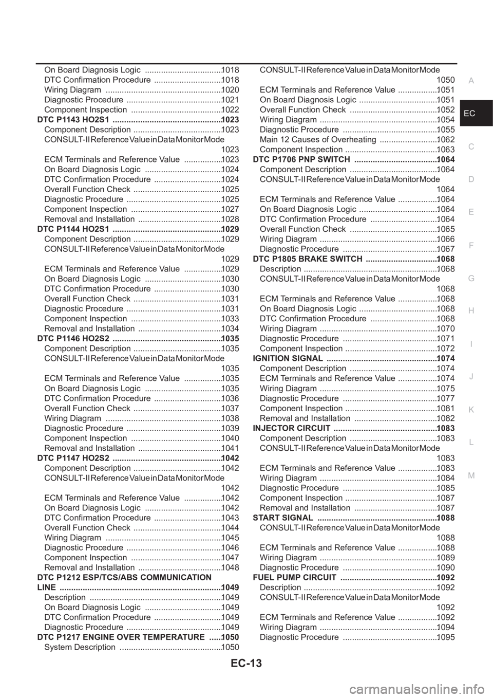
ECA On Board Diagnosis Logic ..................................1018
DTC Confirmation Procedure ..............................1018
Wiring Diagram ...................................................1020
Diagnostic Procedure ..........................................1021
Component Inspection ........................................1022
DTC P1143 HO2S1 ................................................1023
Component Description .......................................1023
CONSULT-II Reference Value in Data Monitor Mode
1023
ECM Terminals and Reference Value .................1023
On Board Diagnosis Logic ..................................1024
DTC Confirmation Procedure ..............................1024
Overall Function Check .......................................1025
Diagnostic Procedure ..........................................1025
Component Inspection ........................................1027
Removal and Installation .....................................1028
DTC P1144 HO2S1 ................................................1029
Component Description .......................................1029
CONSULT-II Reference Value in Data Monitor Mode
1029
ECM Terminals and Reference Value .................1029
On Board Diagnosis Logic ..................................1030
DTC Confirmation Procedure ..............................1030
Overall Function Check .......................................1031
Diagnostic Procedure ..........................................1031
Component Inspection ........................................1033
Removal and Installation .....................................1034
DTC P1146 HO2S2 ................................................1035
Component Description .......................................1035
CONSULT-II Reference Value in Data Monitor Mode
1035
ECM Terminals and Reference Value .................1035
On Board Diagnosis Logic ..................................1035
DTC Confirmation Procedure ..............................1036
Overall Function Check .......................................1037
Wiring Diagram ...................................................1038
Diagnostic Procedure ..........................................1039
Component Inspection ........................................1040
Removal and Installation .....................................1041
DTC P1147 HO2S2 ................................................1042
Component Description .......................................1042
CONSULT-II Reference Value in Data Monitor Mode
1042
ECM Terminals and Reference Value .................1042
On Board Diagnosis Logic ..................................1042
DTC Confirmation Procedure ..............................1043
Overall Function Check .......................................1044
Wiring Diagram ...................................................1045
Diagnostic Procedure ..........................................1046
Component Inspection ........................................1047
Removal and Installation .....................................1048
DTC P1212 ESP/TCS/ABS COMMUNICATION
LINE .......................................................................1049
Description ..........................................................1049
On Board Diagnosis Logic ..................................1049
DTC Confirmation Procedure ..............................1049
Diagnostic Procedure ..........................................1049
DTC P1217 ENGINE OVER TEMPERATURE ......1050
System Description .............................................1050CONSULT-II Reference Value in Data Monitor Mode
1050
ECM Terminals and Reference Value ..................1051
On Board Diagnosis Logic ...................................1051
Overall Function Check .......................................1052
Wiring Diagram ....................................................1054
Diagnostic Procedure ..........................................1055
Main 12 Causes of Overheating ..........................1062
Component Inspection .........................................1063
DTC P1706 PNP SWITCH .....................................1064
Component Description .......................................1064
CONSULT-II Reference Value in Data Monitor Mode
1064
ECM Terminals and Reference Value ..................1064
On Board Diagnosis Logic ...................................1064
DTC Confirmation Procedure ..............................1064
Overall Function Check .......................................1065
Wiring Diagram ....................................................1066
Diagnostic Procedure ..........................................1067
DTC P1805 BRAKE SWITCH ................................1068
Description ...........................................................1068
CONSULT-II Reference Value in Data Monitor Mode
1068
ECM Terminals and Reference Value ..................1068
On Board Diagnosis Logic ...................................1068
DTC Confirmation Procedure ..............................1068
Wiring Diagram ....................................................1070
Diagnostic Procedure ..........................................1071
Component Inspection .........................................1072
IGNITION SIGNAL .................................................1074
Component Description .......................................1074
ECM Terminals and Reference Value ..................1074
Wiring Diagram ....................................................1075
Diagnostic Procedure ..........................................1077
Component Inspection .........................................1081
Removal and Installation .....................................1082
INJECTOR CIRCUIT ..............................................1083
Component Description .......................................1083
CONSULT-II Reference Value in Data Monitor Mode
1083
ECM Terminals and Reference Value ..................1083
Wiring Diagram ....................................................
1084
Diagnostic Procedure ..........................................1085
Component Inspection .........................................1087
Removal and Installation .....................................1087
START SIGNAL .....................................................1088
CONSULT-II Reference Value in Data Monitor Mode
1088
ECM Terminals and Reference Value ..................1088
Wiring Diagram ....................................................1089
Diagnostic Procedure ..........................................1090
FUEL PUMP CIRCUIT ...........................................1092
Description ...........................................................1092
CONSULT-II Reference Value in Data Monitor Mode
1092
ECM Terminals and Reference Value ..................1092
Wiring Diagram ....................................................1094
Diagnostic Procedure ..........................................1095
Page 364 of 3833
EC-14
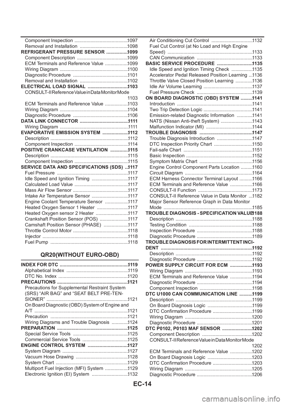
Component Inspection .........................................1097
Removal and Installation .....................................1098
REFRIGERANT PRESSURE SENSOR .................1099
Component Description .......................................1099
ECM Terminals and Reference Value ..................1099
Wiring Diagram ....................................................11 0 0
Diagnostic Procedure ..........................................11 0 1
Removal and Installation .....................................11 0 2
ELECTRICAL LOAD SIGNAL ...............................110 3
CONSULT-II Reference Value in Data Monitor Mode
11 0 3
ECM Terminals and Reference Value ..................11 0 3
Wiring Diagram ....................................................11 0 4
Diagnostic Procedure ..........................................11 0 6
DATA LINK CONNECTOR .....................................1111
Wiring Diagram ....................................................1111
EVAPORATIVE EMISSION SYSTEM ....................111 2
Description ...........................................................111 2
Component Inspection .........................................111 4
POSITIVE CRANKCASE VENTILATION ..............111 5
Description ...........................................................111 5
Component Inspection .........................................111 5
SERVICE DATA AND SPECIFICATIONS (SDS) ...111 7
Fuel Pressure ......................................................111 7
Idle Speed and Ignition Timing ............................111 7
Calculated Load Value .........................................111 7
Mass Air Flow Sensor ..........................................111 7
Intake Air Temperature Sensor ............................111 7
Engine Coolant Temperature Sensor ..................111 7
Heated Oxygen Sensor 1 Heater ........................111 7
Heated Oxygen sensor 2 Heater .........................111 7
Crankshaft Position Sensor (POS) ......................111 7
Camshaft Position Sensor (PHASE) ...................111 7
Throttle Control Motor ..........................................111 8
Injector .................................................................111 8
Fuel Pump ...........................................................111 8
QR20(WITHOUT EURO-OBD)
INDEX FOR DTC ....................................................111 9
Alphabetical Index ...............................................111 9
DTC No. Index .....................................................11 2 0
PRECAUTIONS ......................................................112 1
Precautions for Supplemental Restraint System
(SRS) “AIR BAG” and “SEAT BELT PRE-TEN-
SIONER” ..............................................................11 2 1
On Board Diagnostic (OBD) System of Engine and
A/T .......................................................................11 2 1
Precaution ...........................................................11 2 1
Wiring Diagrams and Trouble Diagnosis .............11 2 4
PREPARATION ......................................................112 5
Special Service Tools .......................................... 11 2 5
Commercial Service Tools ...................................11 2 5
ENGINE CONTROL SYSTEM ...............................112 7
System Diagram ..................................................11 2 7
Vacuum Hose Drawing ........................................11 2 8
System Chart .......................................................11 2 9
Multiport Fuel Injection (MFI) System ..................11 2 9
Electronic Ignition (EI) System ............................11 3 2Air Conditioning Cut Control ................................11 3 2
Fuel Cut Control (at No Load and High Engine
Speed) .................................................................11 3 3
CAN Communication ...........................................11 3 3
BASIC SERVICE PROCEDURE ............................11 35
Idle Speed and Ignition Timing Check .................11 3 5
Accelerator Pedal Released Position Learning ....11 3 6
Throttle Valve Closed Position Learning ..............11 3 6
Idle Air Volume Learning ......................................11 3 7
Fuel Pressure Check ...........................................11 3 9
ON BOARD DIAGNOSTIC (OBD) SYSTEM ..........11 41
Introduction ..........................................................11 4 1
Two Trip Detection Logic ......................................11 4 1
Emission-related Diagnostic Information .............11 4 1
NATS (Nissan Anti-theft System) .........................11 4 3
Malfunction Indicator (MI) ....................................11 4 4
TROUBLE DIAGNOSIS .........................................11 47
Trouble Diagnosis Introduction ............................11 4 7
DTC Inspection Priority Chart ..............................11 5 0
Fail-safe Chart .....................................................11 5 1
Basic Inspection ...................................................11 5 2
Symptom Matrix Chart .........................................11 5 6
Engine Control Component Parts Location ..........11 6 0
Circuit Diagram ....................................................11 6 4
ECM Harness Connector Terminal Layout ...........11 6 6
ECM Terminals and Reference Value ..................11 6 6
CONSULT-II Function ..........................................
11 7 3
CONSULT-II Reference Value in Data Monitor ....11 8 2
Major Sensor Reference Graph in Data Monitor
Mode ....................................................................11 8 5
TROUBLE DIAGNOSIS - SPECIFICATION VALUE 11 88
Description ...........................................................11 8 8
Testing Condition .................................................11 8 8
Inspection Procedure ........................................... 11 8 8
Diagnostic Procedure ........................................... 11 8 9
TROUBLE DIAGNOSIS FOR INTERMITTENT INCI-
DENT ......................................................................11 92
Description ...........................................................11 9 2
Diagnostic Procedure ........................................... 11 9 2
POWER SUPPLY CIRCUIT FOR ECM ..................11 93
Wiring Diagram ....................................................11 9 3
ECM Terminals and Reference Value ..................11 9 4
Diagnostic Procedure ........................................... 11 9 4
Component Inspection .........................................11 9 8
DTC U1000 CAN COMMUNICATION LINE ...........11 99
Description ...........................................................11 9 9
On Board Diagnosis Logic ...................................11 9 9
DTC Confirmation Procedure ...............................11 9 9
Wiring Diagram ....................................................1200
Diagnostic Procedure ........................................... 1201
DTC P0102, P0103 MAF SENSOR ........................1202
Component Description .......................................1202
CONSULT-II Reference Value in Data Monitor Mode
1202
ECM Terminals and Reference Value ..................1202
On Board Diagnosis Logic ...................................1203
DTC Confirmation Procedure ...............................1203
Wiring Diagram ....................................................1205
Diagnostic Procedure ........................................... 1206
Page 365 of 3833
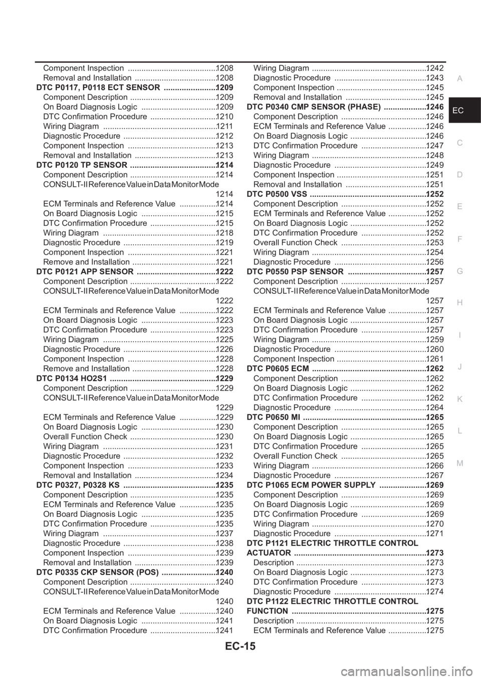
EC-15
C
D
E
F
G
H
I
J
K
L
M
ECA Component Inspection ........................................1208
Removal and Installation .....................................1208
DTC P0117, P0118 ECT SENSOR ........................1209
Component Description .......................................1209
On Board Diagnosis Logic ..................................1209
DTC Confirmation Procedure ..............................1210
Wiring Diagram ...................................................1211
Diagnostic Procedure ..........................................1212
Component Inspection ........................................1213
Removal and Installation .....................................1213
DTC P0120 TP SENSOR .......................................1214
Component Description .......................................1214
CONSULT-II Reference Value in Data Monitor Mode
1214
ECM Terminals and Reference Value .................1214
On Board Diagnosis Logic ..................................1215
DTC Confirmation Procedure ..............................1215
Wiring Diagram ...................................................1218
Diagnostic Procedure ..........................................1219
Component Inspection ........................................1221
Remove and Installation ......................................1221
DTC P0121 APP SENSOR ....................................1222
Component Description .......................................1222
CONSULT-II Reference Value in Data Monitor Mode
1222
ECM Terminals and Reference Value .................1222
On Board Diagnosis Logic ..................................1223
DTC Confirmation Procedure ..............................1223
Wiring Diagram ...................................................1225
Diagnostic Procedure ..........................................1226
Component Inspection ........................................1228
Remove and Installation ......................................1228
DTC P0134 HO2S1 ................................................1229
Component Description .......................................1229
CONSULT-II Reference Value in Data Monitor Mode
1229
ECM Terminals and Reference Value .................1229
On Board Diagnosis Logic ..................................1230
Overall Function Check .......................................1230
Wiring Diagram ...................................................1231
Diagnostic Procedure ..........................................1232
Component Inspection ........................................1233
Removal and Installation .....................................1234
DTC P0327, P0328 KS ..........................................1235
Component Description .......................................1235
ECM Terminals and Reference Value .................1235
On Board Diagnosis Logic ..................................1235
DTC Confirmation Procedure ..............................1235
Wiring Diagram ...................................................1237
Diagnostic Procedure ..........................................1238
Component Inspection ........................................1239
Removal and Installation .....................................1239
DTC P0335 CKP SENSOR (POS) .........................1240
Component Description .......................................1240
CONSULT-II Reference Value in Data Monitor Mode
1240
ECM Terminals and Reference Value .................1240
On Board Diagnosis Logic ..................................1241
DTC Confirmation Procedure ..............................1241Wiring Diagram ....................................................1242
Diagnostic Procedure ..........................................1243
Component Inspection .........................................1245
Removal and Installation .....................................1245
DTC P0340 CMP SENSOR (PHASE) ....................1246
Component Description .......................................1246
ECM Terminals and Reference Value ..................1246
On Board Diagnosis Logic ...................................1246
DTC Confirmation Procedure ..............................1247
Wiring Diagram ....................................................1248
Diagnostic Procedure ..........................................1249
Component Inspection .........................................1251
Removal and Installation .....................................1251
DTC P0500 VSS .....................................................1252
Component Description .......................................1252
ECM Terminals and Reference Value ..................1252
On Board Diagnosis Logic ...................................1252
DTC Confirmation Procedure ..............................1252
Overall Function Check .......................................1253
Wiring Diagram ....................................................1254
Diagnostic Procedure ..........................................1256
DTC P0550 PSP SENSOR ....................................1257
Component Description .......................................1257
CONSULT-II Reference Value in Data Monitor Mode
1257
ECM Terminals and Reference Value ..................1257
On Board Diagnosis Logic ...................................1257
DTC Confirmation Procedure ..............................1257
Wiring Diagram ....................................................1259
Diagnostic Procedure ..........................................1260
Component Inspection .........................................1261
DTC P0605 ECM ....................................................1262
Component Description .......................................1262
On Board Diagnosis Logic ...................................1262
DTC Confirmation Procedure ..............................1262
Diagnostic Procedure ..........................................1264
DTC P0650 MI ........................................................1265
Component Description .......................................1265
On Board Diagnosis Logic ...................................1265
DTC Confirmation Procedure ..............................1265
Overall Function Check .......................................1265
Wiring Diagram ....................................................1266
Diagnostic Procedure ..........................................1267
DTC P1065 ECM POWER SUPPLY ......................1269
Component Description .......................................1269
On Board Diagnosis Logic ...................................1269
DTC Confirmation Procedure ..............................1269
Wiring Diagram ....................................................1270
Diagnostic Procedure ..........................................1271
DTC P1121 ELECTRIC THROTTLE CONTROL
ACTUATOR ............................................................1273
Description ...........................................................1273
On Board Diagnosis Logic ...................................1273
DTC Confirmation Procedure ..............................1273
Diagnostic Procedure ..........................................1274
DTC P1122 ELECTRIC THROTTLE CONTROL
FUNCTION .............................................................1275
Description ...........................................................1275
ECM Terminals and Reference Value ..................1275
Page 366 of 3833
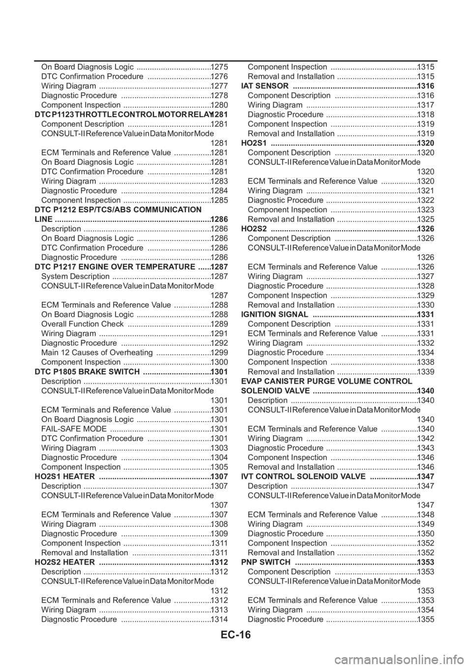
EC-16
On Board Diagnosis Logic ...................................1275
DTC Confirmation Procedure ..............................1276
Wiring Diagram ....................................................1277
Diagnostic Procedure ..........................................1278
Component Inspection .........................................1280
DTC P1123 THROTTLE CONTROL MOTOR RELAY 1281
Component Description .......................................1281
CONSULT-II Reference Value in Data Monitor Mode
1281
ECM Terminals and Reference Value ..................1281
On Board Diagnosis Logic ...................................1281
DTC Confirmation Procedure ..............................1281
Wiring Diagram ....................................................1283
Diagnostic Procedure ..........................................1284
Component Inspection .........................................1285
DTC P1212 ESP/TCS/ABS COMMUNICATION
LINE ........................................................................1286
Description ...........................................................1286
On Board Diagnosis Logic ...................................1286
DTC Confirmation Procedure ..............................1286
Diagnostic Procedure ..........................................1286
DTC P1217 ENGINE OVER TEMPERATURE .......1287
System Description ..............................................1287
CONSULT-II Reference Value in Data Monitor Mode
1287
ECM Terminals and Reference Value ..................1288
On Board Diagnosis Logic ...................................1288
Overall Function Check .......................................1289
Wiring Diagram ....................................................1291
Diagnostic Procedure ..........................................1292
Main 12 Causes of Overheating ..........................1299
Component Inspection .........................................1300
DTC P1805 BRAKE SWITCH ................................1301
Description ...........................................................1301
CONSULT-II Reference Value in Data Monitor Mode
1301
ECM Terminals and Reference Value ..................1301
On Board Diagnosis Logic ...................................1301
FAIL-SAFE MODE ...............................................1301
DTC Confirmation Procedure ..............................1301
Wiring Diagram ....................................................1303
Diagnostic Procedure ..........................................1304
Component Inspection .........................................1305
HO2S1 HEATER ....................................................1307
Description ...........................................................1307
CONSULT-II Reference Value in Data Monitor Mode
1307
ECM Terminals and Reference Value ..................1307
Wiring Diagram ....................................................1308
Diagnostic Procedure ..........................................1309
Component Inspection .........................................1311
Removal and Installation .....................................1311
HO2S2 HEATER ....................................................1312
Description ...........................................................1312
CONSULT-II Reference Value in Data Monitor Mode
1312
ECM Terminals and Reference Value ..................1312
Wiring Diagram ....................................................1313
Diagnostic Procedure ..........................................1314Component Inspection .........................................1315
Removal and Installation ......................................1315
IAT SENSOR ..........................................................1316
Component Description .......................................1316
Wiring Diagram ....................................................1317
Diagnostic Procedure ........................................... 1318
Component Inspection .........................................1319
Removal and Installation ......................................1319
HO2S1 ....................................................................1320
Component Description .......................................1320
CONSULT-II Reference Value in Data Monitor Mode
1320
ECM Terminals and Reference Value ..................1320
Wiring Diagram ....................................................1321
Diagnostic Procedure ........................................... 1322
Component Inspection .........................................1323
Removal and Installation ......................................1325
HO2S2 ....................................................................1326
Component Description .......................................1326
CONSULT-II Reference Value in Data Monitor Mode
1326
ECM Terminals and Reference Value ..................1326
Wiring Diagram ....................................................1327
Diagnostic Procedure ........................................... 1328
Component Inspection .........................................1329
Removal and Installation ......................................1330
IGNITION SIGNAL .................................................1331
Component Description .......................................1331
ECM Terminals and Reference Value ..................1331
Wiring Diagram ....................................................1332
Diagnostic Procedure ........................................... 1334
Component Inspection .........................................1338
Removal and Installation ......................................1339
EVAP CANISTER PURGE VOLUME CONTROL
SOLENOID VALVE ................................................. 1340
Description ...........................................................1340
CONSULT-II Reference Value in Data Monitor Mode
1340
ECM Terminals and Reference Value ..................1340
Wiring Diagram ....................................................1342
Diagnostic Procedure ........................................... 1343
Component Inspection .........................................1346
Removal and Installation ......................................1346
IVT CONTROL SOLENOID VALVE .......................1347
Description ...........................................................1347
CONSULT-II Reference Value in Data Monitor Mode
1347
ECM Terminals and Reference Value ..................1348
Wiring Diagram ....................................................1349
Diagnostic Procedure ........................................... 1350
Component Inspection .........................................1352
Removal and Installation ......................................1352
PNP SWITCH .........................................................1353
Component Description .......................................1353
CONSULT-II Reference Value in Data Monitor Mode
1353
ECM Terminals and Reference Value ..................1353
Wiring Diagram ....................................................1354
Diagnostic Procedure ........................................... 1355
Page 367 of 3833
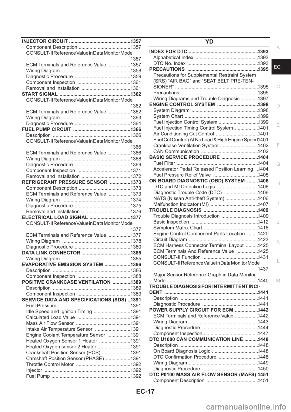
EC-17
C
D
E
F
G
H
I
J
K
L
M
ECA INJECTOR CIRCUIT ..............................................1357
Component Description .......................................1357
CONSULT-II Reference Value in Data Monitor Mode
1357
ECM Terminals and Reference Value .................1357
Wiring Diagram ...................................................1358
Diagnostic Procedure ..........................................1359
Component Inspection ........................................1361
Removal and Installation .....................................1361
START SIGNAL .....................................................1362
CONSULT-II Reference Value in Data Monitor Mode
1362
ECM Terminals and Reference Value .................1362
Wiring Diagram ...................................................1363
Diagnostic Procedure ..........................................1364
FUEL PUMP CIRCUIT ...........................................1366
Description ..........................................................1366
CONSULT-II Reference Value in Data Monitor Mode
1366
ECM Terminals and Reference Value .................1366
Wiring Diagram ...................................................1368
Diagnostic Procedure ..........................................1369
Component Inspection ........................................1371
Removal and Installation .....................................1372
REFRIGERANT PRESSURE SENSOR ................1373
Component Description .......................................1373
ECM Terminals and Reference Value .................1373
Wiring Diagram ...................................................1374
Diagnostic Procedure ..........................................1375
Removal and Installation .....................................1376
ELECTRICAL LOAD SIGNAL ...............................1377
CONSULT-II Reference Value in Data Monitor Mode
1377
ECM Terminals and Reference Value .................1377
Wiring Diagram ...................................................1378
Diagnostic Procedure ..........................................1380
DATA LINK CONNECTOR ....................................1385
Wiring Diagram ...................................................1385
EVAPORATIVE EMISSION SYSTEM ....................1386
Description ..........................................................1386
Component Inspection ........................................1388
POSITIVE CRANKCASE VENTILATION ..............1389
Description ..........................................................1389
Component Inspection ........................................1389
SERVICE DATA AND SPECIFICATIONS (SDS) ...1391
Fuel Pressure ......................................................1391
Idle Speed and Ignition Timing ............................1391
Calculated Load Value ........................................1391
Mass Air Flow Sensor .........................................1391
Intake Air Temperature Sensor ...........................1391
Engine Coolant Temperature Sensor ..................1391
Heated Oxygen Sensor 1 Heater ........................1391
Heated Oxygen sensor 2 Heater .........................1391
Crankshaft Position Sensor (POS) ......................1391
Camshaft Position Sensor (PHASE) ...................1391
Throttle Control Motor ......................................... 1392
Injector ................................................................1392
Fuel Pump ...........................................................1392
YD
INDEX FOR DTC ....................................................1393
Alphabetical Index ...............................................1393
DTC No. Index .....................................................1393
PRECAUTIONS .....................................................1395
Precautions for Supplemental Restraint System
(SRS) “AIR BAG” and “SEAT BELT PRE-TEN-
SIONER” ..............................................................1395
Precautions ..........................................................1395
Wiring Diagrams and Trouble Diagnosis .............1397
ENGINE CONTROL SYSTEM ...............................1398
System Diagram ..................................................1398
System Chart .......................................................1399
Fuel Injection Control System ..............................1399
Fuel Injection Timing Control System ..................1401
Air Conditioning Cut Control ................................1401
F u e l C u t C o n t r o l ( A t N o L o a d & H i g h E n g i n e S p e e d ) 1401
Crankcase Ventilation System .............................1402
CAN Communication ...........................................1402
BASIC SERVICE PROCEDURE ............................1404
Fuel Filter .............................................................1404
Accelerator Pedal Released Position Learning ...1404
Fuel Pressure Relief Valve ..................................1405
ON BOARD DIAGNOSTIC (OBD) SYSTEM .........1406
DTC and MI Detection Logic ...............................1406
Diagnostic Trouble Code (DTC) ..........................1406
NATS (Nissan Anti-theft System) ........................1406
Malfunction Indicator (MI) ....................................1407
TROUBLE DIAGNOSIS .........................................1409
Trouble Diagnosis Introduction ............................1409
Basic Inspection ..................................................1412
Symptom Matrix Chart .........................................1416
Engine Control Component Parts Location .........1420
Circuit Diagram ....................................................1423
ECM Harness Connector Terminal Layout ..........1425
ECM Terminals And Reference Value .................1425
CONSULT-II Function ..........................................1431
CONSULT-II Reference Value in Data Monitor Mode
1437
Major Sensor Reference Graph in Data Monitor
Mode ....................................................................1440
TROUBLE DIAGNOSIS FOR INTERMITTENT INCI-
DENT ......................................................................1441
Description ...........................................................1441
Diagnostic Procedure ..........................................1441
POWER SUPPLY CIRCUIT FOR ECM ..................1442
ECM Terminals and Reference Value ..................1442
Wiring Diagram ....................................................1443
Diagnostic Procedure ..........................................1444
Component Inspection .........................................1447
DTC U1000 CAN COMMUNICATION LINE ...........1448
Description ...........................................................1448
On Board Diagnosis Logic ...................................1448
DTC Confirmation Procedure ..............................1448
Wiring Diagram ....................................................1449
Diagnostic Procedure ..........................................1450
DTC P0100 MASS AIR FLOW SENSOR (MAFS) .1451
Component Description .......................................1451
Page 368 of 3833
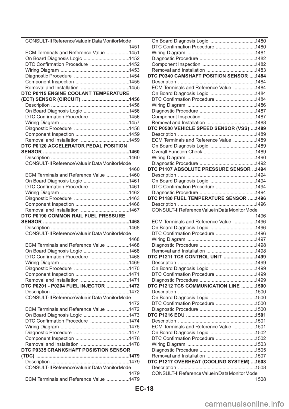
EC-18
CONSULT-II Reference Value in Data Monitor Mode
1451
ECM Terminals and Reference Value ..................1451
On Board Diagnosis Logic ...................................1452
DTC Confirmation Procedure ..............................1452
Wiring Diagram ....................................................1453
Diagnostic Procedure ..........................................1454
Component Inspection .........................................1455
Removal and Installation .....................................1455
DTC P0115 ENGINE COOLANT TEMPERATURE
(ECT) SENSOR (CIRCUIT) ....................................1456
Description ...........................................................1456
On Board Diagnosis Logic ...................................1456
DTC Confirmation Procedure ..............................1456
Wiring Diagram ....................................................1457
Diagnostic Procedure ..........................................1458
Component Inspection .........................................1459
Removal and Installation .....................................1459
DTC P0120 ACCELERATOR PEDAL POSITION
SENSOR .................................................................1460
Description ...........................................................1460
CONSULT-II Reference Value in Data Monitor Mode
1460
ECM Terminals and Reference Value ..................1460
On Board Diagnosis Logic ...................................1461
DTC Confirmation Procedure ..............................1461
Wiring Diagram ....................................................1462
Diagnostic Procedure ..........................................1463
Component Inspection .........................................1466
Removal and Installation .....................................1467
DTC P0190 COMMON RAIL FUEL PRESSURE
SENSOR .................................................................1468
Description ...........................................................1468
CONSULT-II Reference Value in Data Monitor Mode
1468
ECM Terminals and Reference Value ..................1468
On Board Diagnosis Logic ...................................1468
DTC Confirmation Procedure ..............................1468
Wiring Diagram ....................................................1469
Diagnostic Procedure ..........................................1470
Component Inspection .........................................1471
Removal and Installation .....................................1471
DTC P0201 - P0204 FUEL INJECTOR ..................1472
Description ...........................................................1472
CONSULT-II Reference Value in Data Monitor Mode
1472
ECM Terminals and Reference Value ..................1472
On Board Diagnosis Logic ...................................1473
DTC Confirmation Procedure ..............................1474
Wiring Diagram ....................................................1475
Diagnostic Procedure ..........................................1477
Component Inspection .........................................
1478
Removal and Installation .....................................1478
DTC P0335 CRANKSHAFT POSISTION SENSOR
(TDC) ......................................................................1479
Description ...........................................................1479
CONSULT-II Reference Value in Data Monitor Mode
1479
ECM Terminals and Reference Value ..................1479On Board Diagnosis Logic ...................................1480
DTC Confirmation Procedure ...............................1480
Wiring Diagram ....................................................1481
Diagnostic Procedure ........................................... 1482
Component Inspection .........................................1482
Removal and Installation ......................................1483
DTC P0340 CAMSHAFT POSITION SENSOR ......1484
Description ...........................................................1484
ECM Terminals and Reference Value ..................1484
On Board Diagnosis Logic ...................................1484
DTC Confirmation Procedure ...............................1484
Wiring Diagram ....................................................1486
Diagnostic Procedure ........................................... 1487
Component Inspection .........................................1487
Removal and Installation ......................................1488
DTC P0500 VEHICLE SPEED SENSOR (VSS) .....1489
Description ...........................................................1489
ECM Terminals and Reference Value ..................1489
On Board Diagnosis Logic ...................................1489
Overall Function Check ........................................1489
Wiring Diagram ....................................................1490
Diagnostic Procedure ........................................... 1492
DTC P1107 ABSOLUTE PRESSURE SENSOR ....1494
Description ...........................................................1494
On Board Diagnosis Logic ...................................1494
DTC Confirmation Procedure ...............................1494
Diagnostic Procedure ........................................... 1494
DTC P1180 FUEL TEMPERATURE SENSOR .......1496
Description ...........................................................1496
CONSULT-II Reference Value in Data Monitor Mode
1496
ECM Terminals and Reference Value ..................1496
On Board Diagnosis Logic ...................................1496
DTC Confirmation Procedure ...............................1496
Wiring Diagram ....................................................1497
Diagnostic Procedure ........................................... 1498
Removal and Installation ......................................1498
DTC P1211 TCS CONTROL UNIT .........................1499
Description ...................................................
........1499
On Board Diagnosis Logic ...................................1499
DTC Confirmation Procedure ...............................1499
Diagnostic Procedure ........................................... 1499
DTC P1212 TCS COMMUNICATION LINE ............1500
Description ...........................................................1500
On Board Diagnosis Logic ...................................1500
DTC Confirmation Procedure ...............................1500
Diagnostic Procedure ........................................... 1500
DTC P1216 EDU .....................................................1501
Description ...........................................................1501
ECM Terminals and Reference Value ..................1501
On Board Diagnosis Logic ...................................1502
DTC Confirmation Procedure ...............................1502
Wiring Diagram ....................................................1503
Diagnostic Procedure ........................................... 1505
Removal and Installation ......................................1507
DTC P1217 OVERHEAT (COOLING SYSTEM) .....1508
Description ...........................................................1508
CONSULT-II Reference Value in Data Monitor Mode
1508
Page 369 of 3833
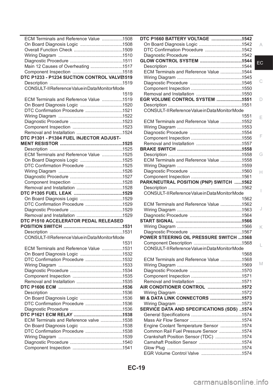
EC-19
C
D
E
F
G
H
I
J
K
L
M
ECA ECM Terminals and Reference Value .................1508
On Board Diagnosis Logic ..................................1508
Overall Function Check .......................................1509
Wiring Diagram ...................................................1510
Diagnostic Procedure ..........................................1511
Main 12 Causes of Overheating ..........................1517
Component Inspection ........................................1518
DTC P1233 - P1234 SUCTION CONTROL VALVE 1519
Description ..........................................................1519
CONSULT-II Reference Value in Data Monitor Mode
1519
ECM Terminals and Reference Value .................1519
On Board Diagnosis Logic ..................................1520
DTC Confirmation Procedure ..............................1521
Wiring Diagram ...................................................1522
Diagnostic Procedure ..........................................1523
Component Inspection ........................................1523
Removal and Installation .....................................1524
DTC P1301 - P1304 FUEL INJECTOR ADJUST-
MENT RESISTOR .................................................. 1525
Description ..........................................................1525
ECM Terminals and Reference Value .................1525
On Board Diagnosis Logic ..................................1525
DTC Confirmation Procedure ..............................1525
Wiring Diagram ...................................................1526
Diagnostic Procedure ..........................................1527
Component Inspection ........................................1528
Removal and Installation .....................................1528
DTC P1305 FUEL LEAK .......................................1529
On Board Diagnosis Logic ..................................1529
DTC Confirmation Procedure ..............................1529
Diagnostic Procedure ..........................................1529
Removal and Installation .....................................1529
DTC P1510 ACCELERATOR PEDAL RELEASED
POSITION SWITCH ...............................................1531
Description ..........................................................1531
CONSULT-II Reference Value in Data Monitor Mode
1531
ECM Terminals and Reference Value .................1531
On Board Diagnosis Logic ..................................1532
DTC Confirmation Procedure ..............................1532
Wiring Diagram ...................................................1533
Diagnostic Procedure ..........................................1534
Component Inspection ........................................1535
Removal and Installation .....................................1535
DTC P1606 ECM ...................................................1536
Description ..........................................................1536
On Board Diagnosis Logic ..................................1536
DTC Confirmation Procedure ..............................
1536
Diagnostic Procedure ..........................................1536
DTC P1621 ECM RELAY .......................................1538
ECM Terminals and Reference valve ..................1538
On Board Diagnosis Logic ..................................1538
DTC Confirmation Procedure ..............................1538
Wiring Diagram ...................................................1539
Diagnostic Procedure ..........................................1540
Component Inspection ........................................1541DTC P1660 BATTERY VOLTAGE .........................1542
On Board Diagnosis Logic ...................................1542
DTC Confirmation Procedure ..............................1542
Diagnostic Procedure ..........................................1542
GLOW CONTROL SYSTEM ..................................1544
Description ...........................................................1544
ECM Terminals and Reference Value ..................1544
Wiring Diagram ....................................................1545
Diagnostic Procedure ..........................................1546
Component Inspection .........................................1550
Removal and Installation .....................................1550
EGR VOLUME CONTROL SYSTEM .....................1551
Description ...........................................................1551
CONSULT-II Reference Value in Data Monitor Mode
1551
ECM Terminals and Reference Value ..................1552
Wiring Diagram ....................................................1553
Diagnostic Procedure ..........................................1554
Component Inspection .........................................1556
Removal and Installation .....................................1557
BRAKE SWITCH ....................................................1558
Description ...........................................................1558
ECM Terminals and Reference Value ..................1558
Wiring Diagram ....................................................1559
Diagnostic Procedure ..........................................1560
Component Inspection .........................................1561
PARK/NEUTRAL POSITION (PNP) SWITCH .......1562
Description ...........................................................1562
CONSULT-II Reference Value in Data Monitor Mode
1562
ECM Terminals and Reference Value ..................1562
Wiring Diagram ....................................................1563
Diagnostic Procedure ..........................................1564
START SIGNAL .....................................................1566
Wiring Diagram ....................................................1566
Diagnostic Procedure ..........................................1567
POWER STEERING OIL PRESSURE SWITCH ....1568
Component Description .......................................1568
CONSULT-II Reference Value in Data Monitor Mode
1568
ECM Terminals and Reference Value ..................1568
Wiring Diagram ....................................................1569
Diagnostic Procedure ..........................................1570
Component Inspection .........................................1571
Removal and Installation .....................................1571
AIR CONDITIONER CONTROL ............................1572
Wiring Diagram ....................................................1572
MI & DATA LINK CONNECTORS ..........................1573
Wiring Diagram ....................................................1573
SERVICE DATA AND SPECIFICATIONS (SDS) ...1574
General Specifications ......................................... 1574
Mass Air Flow Sensor ..........................................1574
Engine Coolant Temperature Sensor ..................1574
Common Rail Fuel Pressure Sensor ...................1574
Crankshaft Position Sensor (TDC) ......................1574
Camshaft Position Sensor ...................................1574
Glow Plug ............................................................1574
EGR Volume Control Valve .................................1574
Page 370 of 3833
![NISSAN X-TRAIL 2001 Service Repair Manual EC-20
[QR25(WITH EURO-OBD)]
INDEX FOR DTC
[QR25(WITH EURO-OBD)]INDEX FOR DTCPFP:00024
Alphabetical IndexEBS00M01
Check if the vehicle is a model with Euro-OBD (E-OBD) system or not by the “Type appr NISSAN X-TRAIL 2001 Service Repair Manual EC-20
[QR25(WITH EURO-OBD)]
INDEX FOR DTC
[QR25(WITH EURO-OBD)]INDEX FOR DTCPFP:00024
Alphabetical IndexEBS00M01
Check if the vehicle is a model with Euro-OBD (E-OBD) system or not by the “Type appr](/img/5/57405/w960_57405-369.png)
EC-20
[QR25(WITH EURO-OBD)]
INDEX FOR DTC
[QR25(WITH EURO-OBD)]INDEX FOR DTCPFP:00024
Alphabetical IndexEBS00M01
Check if the vehicle is a model with Euro-OBD (E-OBD) system or not by the “Type approval number” on the
identification plate. Refer to GI-43, "
IDENTIFICATION PLATE" .
NOTE:
If DTC U1000 is displayed with other DTC, first perform the trouble diagnosis for DTC U1000. Refer to
EC-122
.
×: Applicable –: Not applicable
Items
(CONSULT-II screen terms)DTC*
1
TripMI lighting
upReference page
CONSULT-II
GST*
2ECM*3
APP SENSOR P2138 2138 1×EC-373
APP SEN 1/CIRC P2122 2122 1×EC-355
APP SEN 1/CIRC P2123 2123 1×EC-355
APP SEN 2/CIRC P2127 2127 1×EC-361
APP SEN 2/CIRC P2128 2128 1×EC-361
A/T 1ST GR FNCTN P0731 0731 2×AT- 1 3 1
A/T 2ND GR FNCTN P0732 0732 2×AT- 1 3 7
A/T 3RD GR FNCTN P0733 0733 2×AT- 1 4 3
A/T 4TH GR FNCTN P0734 0734 2×AT- 1 4 9
ATF TEMP SEN/CIRC P0710 0710 2×AT- 11 6
BRAKE SW/CIRCUIT P1805 1805 2 –EC-349
CAN COMM CIRCUIT*6U1000
1000*51×EC-122
CKP SEN/CIRCUIT P0335 0335 2×EC-227
CMP SEN/CIRCUIT P0340 0340 2×EC-233
CTP LEARNING P1225 1225 2 –EC-337
CTP LEARNING P1226 1226 2 –EC-339
CYL 1 MISFIRE P0301 0301 2×EC-217
CYL 2 MISFIRE P0302 0302 2×EC-217
CYL 3 MISFIRE P0303 0303 2×EC-217
CYL 4 MISFIRE P0304 0304 2×EC-217
ECM P0605 0605 1 or 2× or –EC-260
ECM BACK UP/CIRC P1065 1065 2×EC-267
ECT SEN/CIRCUIT P0117 0117 1×EC-149
ECT SEN/CIRCUIT P0118 0118 1×EC-149
ENG OVER TEMP P1217 1217 1×EC-323
ENGINE SPEED SIG P0725 0725 2×AT- 1 2 7
ETC ACTR P1121 1121 1 or 2×EC-276
ETC FUNCTION/CIRC P1122 1122 1×EC-278
ETC MOT P1128 1128 1×EC-290
ETC MOT PWR P1124 1124 1×EC-285
ETC MOT PWR P1126 1126 1×EC-285
FUEL SYS-LEAN-B1 P0171 0171 2×EC-200
FUEL SYS-RICH-B1 P0172 0172 2×EC-206
HO2S1 (B1) P0132 0132 2×EC-163
HO2S1 (B1) P0133 0133 2×EC-169