fog light NISSAN X-TRAIL 2001 Service Service Manual
[x] Cancel search | Manufacturer: NISSAN, Model Year: 2001, Model line: X-TRAIL, Model: NISSAN X-TRAIL 2001Pages: 3833, PDF Size: 39.49 MB
Page 1762 of 3833

EC-1412
[YD]
TROUBLE DIAGNOSIS
Worksheet Sample
Basic InspectionEBS0037E
Precaution:
Perform Basic Inspection without electrical or mechanical loads applied;
●Headlamp switch is OFF.
●On vehicles equipped with daytime light systems, set lighting switch to the 1st position to light
only small lamps.
●Air conditioner switch is OFF.
●Rear defogger switch is OFF.
●Steering wheel is in the straight-ahead position, etc.
MTBL0533
Page 1788 of 3833

EC-1438
[YD]
TROUBLE DIAGNOSIS
ACCEL SEN 2*●Ignition switch: ON
(Engine stopped)Accelerator pedal: fully released 0.3 - 1.8V
Accelerator pedal: fully depressed More than 3.0V
OFF ACCEL SW
●Ignition switch: ON
(Engine stopped)Accelerator pedal: fully released ON
Accelerator pedal: slightly
depressed OFF
MAS AIR/FL SE
●Engine: After warming up
●Air conditioner switch: OFF
●Shift lever: Neutral position
●No-loadIdle 1.0 - 2.5V
2,000 rpm 2.1 - 2.7V
BATTERY VOLT
●Ignition switch: ON (Engine stopped) 11 - 14V
P/N POSI SW
●Ignition switch: ONShift lever: Neutral position ON
Except above OFF
START SIGNAL
●Ignition switch: ON → START → ON OFF → ON → OFF
PW/ST SIGNAL
●Engine: After warming up, idle
the engineSteering wheel is in neutral posi-
tion. (Forward direction)OFF
Steering wheel is turned. ON
BRAKE SW
●Ignition switch: ONBrake pedal: Fully released OFF
Brake pedal: Slightly depressed ON
IGN SW
●Ignition switch: ON → OFF ON → OFF
ACT CR PRESS
●Engine: After warming up
●Air conditioner switch: OFF
●Shift lever: Neutral position
●No-loadIdle 30 - 40 MPa
2,000 rpm 40 - 50 MPa
SUCTION CV
●Engine: After warming up
●Air conditioner switch: OFF
●Shift lever: Neutral position
●No-loadIdle 70.0 - 71.5°CA
2,000 rpm 73.5 - 75.0°CA
MAIN INJ WID
●Engine: After warming up
●Shift lever: Neutral position
●Idle speedNo-load 0.68 - 0.78 msec
Air conditioner switch: ON
Rear window defogger switch: ON0.78 - 0.88 msec
GLOW RLY Refer to EC-1544, "
GLOW CONTROL SYSTEM" .
COOLING FAN
●When cooling fan is stopped. OFF
●When cooling fans operate at low speed. LOW
●When cooling fans operate at high speed. HIGH
EGR VOL CON/V
●Engine: After warming up
●Air conditioner switch: OFF
●Shift lever: Neutral position
●No-loadAfter one minute at idle More than 10 steps
Revving engine from idle to 3,600
rpm0 step
INT/A VOLUME
●Engine: After warming up, idle the engine 150 - 450 mg/st MONITOR ITEM CONDITION SPECIFICATION
Page 3173 of 3833
REAR WINDOW DEFOGGER
GW-21
C
D
E
F
G
H
J
K
L
MA
B
GW
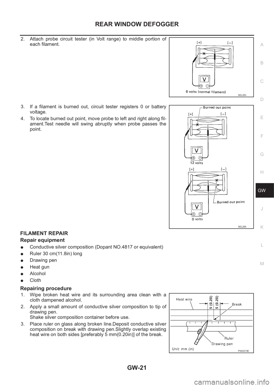
2. Attach probe circuit tester (in Volt range) to middle portion of
each filament.
3. If a filament is burned out, circuit tester registers 0 or battery
voltage.
4. To locate burned out point, move probe to left and right along fil-
ament.Test needle will swing abruptly when probe passes the
point.
FILAMENT REPAIR
Repair equipment
●Conductive silver composition (Dopant NO.4817 or equivalent)
●Ruler 30 cm(11.8in) long
●Drawing pen
●Heat gun
●Alcohol
●Cloth
Repairing procedure
1. Wipe broken heat wire and its surrounding area clean with a
cloth dampened alcohol.
2. Apply a small amount of conductive silver composition to tip of
drawing pen.
Shake silver composition container before use.
3. Place ruler on glass along broken line.Deposit conductive silver
composition on break with drawing pen.Slightly overlap existing
heat wire on both sides [preferably 5 mm(0.20in)] of the break.
SEL263
SEL265
PIIA0215E
Page 3514 of 3833

LT-24
LIGHTING AND TURN SIGNAL SWITCH
LIGHTING AND TURN SIGNAL SWITCH
PFP:25540
Removal and InstallationEKS0034F
1. Remove the steering column cover. Refer to PS-9, "STEERING
COLUMN" in “POWER STEERING SYSTEM (PS)” section.
2. Remove lighting and turn signal switch fixing pawls and remove
the lighting and turn signal switch from the spiral cable.
3. Disconnect the lighting and turn signal switch connector.
Switch Circuit InspectionEKS0034G
Using circuit tester, check continuity between the lighting and turn signal switch connector terminals in each
operation status of the switch.
Lighting switch is refer toLT- 5 , "
Wiring Diagram — H/LAMP —"
Turn signal lamp switch is refer toLT-19, "Wiring Diagram — TURN —"
Front fog lamp switch is refer toLT-34, "Wiring Diagram — F/FOG —"
Rear fog lamp switch is refer toLT- 3 7 , "Wiring Diagram -R/FOG-/Without Front Fog Lamp" ,LT-38, "Wiring Dia-
gram -R/FOG-/With Front Fog Lamp"
SKIA4168E
Page 3523 of 3833

FRONT FOG LAMP
LT-33
C
D
E
F
G
H
I
J
L
MA
B
LT
FRONT FOG LAMP PFP:00011
System Description EKS003DF
DESCRIPTION
Power is supplied at all times to fog lamp relay terminal 3
●through 15A fuse (No. 42, located in the fuse and fusible link box).
With the lighting switch in the 2ND position and LOW (“B”) position, power is supplied
●through 10A fuse (No. 31, located in the fuse and fusible link box).
●to lighting switch terminal 11
●through terminal 12 of the lighting switch
●to fog lamp switch terminal 32
●through terminal 31 of the fog lamp switch
●to fog lamp relay terminal 2.
FOG LAMP OPERATION
The fog lamp switch is built into the combination switch. The lighting switch must be in the 1st or 2nd position
for fog lamp operation.
With the fog lamp switch in the ON position, ground is supplied
●to fog lamp relay terminal 1
●through the fog lamp switch and body grounds E24 and E50.
The fog lamp relay is energized and power is supplied
●from fog lamp relay terminal 5
●to terminal 1 of each fog lamp.
Ground is supplied to terminal 2 of each fog lamp through body grounds E24 and E50.
With power and ground supplied, the fog lamps illuminate.
Page 3535 of 3833

ILLUMINATION
LT-45
C
D
E
F
G
H
I
J
L
MA
B
LT
ILLUMINATIONPFP:27545
System Description EKS003C7
Power is supplied at all times
●through 10A fuse [No. 31, located in the fuse and fusible link box]
●to lighting switch terminal 11.
The lighting switch must be in the 1ST or 2ND position for illumination.
The following chart shows the power and ground connector terminals for the components included in the illu-
mination system.
Component Connector No. Power terminal Ground terminal
Headlamp washier switch M23 3 4
Headlamp aiming switch M24 3 4
Door mirror remote control
switchM26 10 1
ESP off switch M25 3 4
Hazard switch M51 7 8
4WD mode switch M39 4 3
Rear window defogger switch M50 5 6
A/C auto amp. M52 12 11
Combination meter
(LHD models)M46 56 66
Combination meter
(RHD models)M46 45 56
Audio M42 2 1
CD auto changer M82 34 35
Heater control panel M55 2 6
A/T device M58 3 4
Cigarette lighter M56 3 2
Heated seat switch LH
(LHD models)B131 5 6
Heated seat switch RH
(LHD models)B132 5 6
Heated seat switch LH
(RHD models)B35 5 6
Heated seat switch RH
(RHD models)B34 5 6
Page 3659 of 3833
TIME CONTROL UNIT
BCS-3
C
D
E
F
G
H
I
J
L
MA
B
BCS
TIME CONTROL UNITPFP:28491
DescriptionEKS002ZU
OUTLINE
The time control unit totally controls the following body electrical system operations.
●Warning chime
●Rear defogger
●Power door lock
●Interior lamp
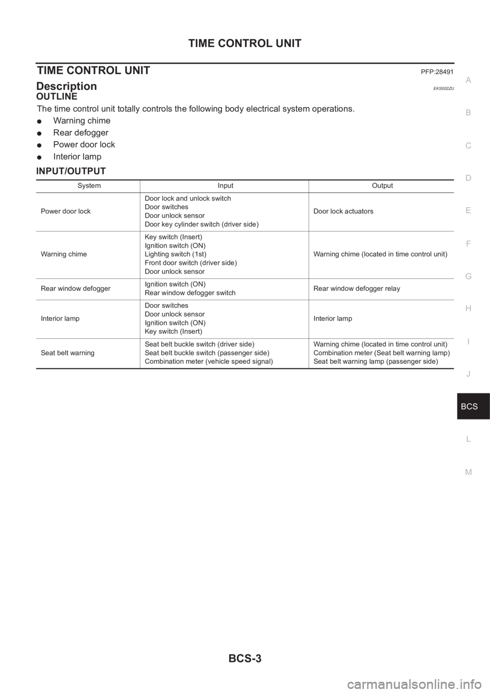
INPUT/OUTPUT
System Input Output
Power door lockDoor lock and unlock switch
Door switches
Door unlock sensor
Door key cylinder switch (driver side)Door lock actuators
Warning chimeKey switch (Insert)
Ignition switch (ON)
Lighting switch (1st)
Front door switch (driver side)
Door unlock sensorWarning chime (located in time control unit)
Rear window defoggerIgnition switch (ON)
Rear window defogger switchRear window defogger relay
Interior lampDoor switches
Door unlock sensor
Ignition switch (ON)
Key switch (Insert)Interior lamp
Seat belt warningSeat belt buckle switch (driver side)
Seat belt buckle switch (passenger side)
Combination meter (vehicle speed signal)Warning chime (located in time control unit)
Combination meter (Seat belt warning lamp)
Seat belt warning lamp (passenger side)
Page 3661 of 3833

TIME CONTROL UNIT
BCS-5
C
D
E
F
G
H
I
J
L
MA
B
BCS
Time Control Unit Inspection TableEKS002ZW
Terminal
No.Wire
colorConnections Operation condition Voltage (Approximate values)
1 L/B Power source (Fuse) — 12V
3 L/Y Super lock actuator Door key cylinder switchFree 0V
Released 12V
4G/RPassenger and rear doors lock
actuatorDoor lock/unlock switchFree 0V
Unlocked 12V
6 Y/R Super lock actuator Door key cylinder switchFree 0V
Sat 12V
8W/BCombination meter [seat belt
(driver side)]Seat belt warning lamp (driver side) is
illuminated (seat belt is unfastened).12V
Seat belt warning lamp (driver side) is
not illuminated (seat belt is fastened).0
10 W Power source (C/B) — 12V
11 LFront door lock actuator (driver
side)Door lock/unlock switchFree 0V
Unlocked 12V
14 R/B Door lock actuator Door lock/unlock switchFree 0V
Locked 12V
15 W/GSeat belt warning lamp (passen-
ger side)Seat belt warning lamp (passenger
side) is illuminated (seat belt is unfas-
tened).12V
Seat belt warning lamp (passenger
side) is not illuminated (seat belt is
unfastened).0
16 B Ground — 0V
17 G Ignition switch (ON) — 12V
18 W/L Ignition key switch (Insert)Key inserted → key removed from
Ignition key cylinder12V → 0V
19 R/L Lighting switch 1ST, 2ND position: ON → OFF 12V → 0V
20 GY Door lock/Unlock switch Neutral → Locks 5V → 0V
21 BR/WSeat belt buckle switch (driver
side)Seat be lt buckle switch (d river side) is
unfastened.*10
Seat be lt buckle switch (d river side) is
fastened.*112V
22 G/ORSeat belt buckle switch (passen-
ger side)Seat belt buckle switch (passenger
side) is unfastened.0
Seat belt buckle switch (passenger
side) is fastened.12V
23 PU Door lock/Unlock switch Neutral → Unlocks 5V → 0V
24 OR/LDoor key cylinder switch (driver
side)OFF (Neutral) → ON (Locked) 5V → 0V
25 W/LDoor key cylinder switch (driver
side)OFF (Neutral) → ON (Unlocked) 5V → 0V
26 R/Y Interior room lampWhen interior room lamp is operated
using remote controller (Lamp switch
is “DOOR” position)12V → 0V
27 G/W Rear window defogger relayOFF→ ON (Ignition key is in “ON”
position)12V → 0V
28 Y/G Door unlock sensor (driver side) Driver door: Locked → Unlocked 5V → 0V
29 Y/L Door unlock sensor (Passenger) Passenger door: Locked → Unlocked 5V → 0V
Page 3764 of 3833

PG-60
HARNESS
Wiring Diagram Codes (Cell Codes)
EKS0032J
Use the chart below to find out what each wiring diagram code stands for.
Refer to the wiring diagram code in the alphabetical index to find the location (page number) of each wiring
diagram.
Code Section Wiring Diagram Name
1STSIG AT A/T 1st Signal
2NDSIG AT A/T 2nd Signal
3RDSIG AT A/T 3rd Signal
4THSIG AT A/T 4th Signal
4WD BRC 4WD Control system
A/C ATC Air Conditioner
ABS BRC ABS Control System
APPS EC Accelerator Pedal Position (APP) Sensor
APRSW EC Accelerator Pedal Released Position Sensor
AT/IND DI A/T Indicator
AUDIO AV Audio
BA/FTS AT A/T Fluid Temperature Sensor and TCM Power Supply
BACK/L LT Back-up Lamp
BRK/SW EC Brake Switch
CAN EC,AT CAN Communication Line
CAN LAN CAN System
CHARGE SC Charging System
CHIME DI Warning Chime
CIGAR WW Cigarette Lighter
CLOCK DI Clock
CKPS EC Crankshaft Position Sensor
CMPS EC Camshaft Position Sensor
COOL/F EC Cooling Fan Control
CRFPS EC Common Rail Fuel Pressure Sensor
D/LOCK BL Power Door Lock
DEF GW Rear Window Defogger
DTRL LT Headlamp - With Daytime Light System
ECM/PW EC ECM Power
ECMRLY EC ECM Relay
ECTS EC Engine Coolant Temperature Sensor
EGRC/V EC EGR Volume Control Valve
ENGSS AT Engine Speed Signal
ETC1 EC Electric Throttle Function
ETC2 EC Electric Throttle Control Motor Relay
ETC3 EC Electric Throttle Control Motor
F/FOG LT Front Fog Lamp
FIAR EC Fuel Injector Adjustment resister
FRO2 EC Heated Oxygen Sensor 1 (Front)
FRO2/H EC Heated Oxygen Sensor 1 Heater (Front)
FTS EC Fuel Temperature Sensor
FTS AT A/T Fluid Temperature Sensor
Page 3828 of 3833

IDX-4
ALPHABETICAL INDEX
Cylinder head bolt tightening(YD22DDTi) ....... EM-184
Cylinder head gasket selection(YD22DDTi) ... EM-185
Cylinder head(QR20DE•QR25DE) ................... EM-59
Cylinder head(YD22DDTi) .............................. EM-182
D
Data link connector .......... EC-424
,EC-745,EC-1111,
EC-1385
Data link connector for Consult ........... EC-96,EC-488,
EC-827
,EC-1174,EC-1431
Daytime light system ............................................. LT-9
Daytime running light - See Daytime light system LT-9
DEF - Wiring diagram ....................................... GW-15
Desiccant Assembly ....................... ATC-30,ATC-146
Diagnosis sensor unit ..................................... SRS-40
Diagnostic trouble code (DTC) ...................... EC-1406
Diagnostic trouble code (DTC) for OBD system EC-20,
EC-47
,EC-432,EC-454,EC-753,EC-779,EC-1119,
EC-1141
,EC-1393
Diagnostic trouble code (DTC) inspection priority chart
EC-70
,EC-463,EC-802,EC-1150
Differential gear (FF M/T) ..................... MT-21,MT-26
DLC - Wiring diagram ...... EC-424,EC-745,EC-1111,
EC-1385
Door glass ........................................... GW-44,GW-46
Door glass Fitting Adjustment ............. GW-44,GW-46
Door lock ................................................. BL-65,BL-68
Door mirror ........................................................ GW-49
Door trim ............................................................. EI-23
Door, front ............................................................ BL-8
Door, rear ............................................................. BL-8
Drive belt inspection(QR20DE•QR25DE) ......... MA-19
Drive belt inspection(YD22DDTi) ...................... MA-26
Drive belt(QR20DE•QR25DE) .......................... EM-12
Drive belt(YD22DDTi) ..................................... EM-118
Drive shaft (front) ............................................. FAX-11
Drive shaft (rear) ............................................... RAX-9
Driver air bag .................................................. SRS-29
Dropping resistor (A/T) ...................... AT-169,AT-402
DTC work support .............................. EC-103,EC-834
DTRL - Wiring diagram ......................................... LT-9
Dual pressure switch ........ ATC-18,ATC-85,ATC-143
Duct and grilles ............................... ATC-127,MTC-29
E
ECM input/output signal ....... EC-87
,EC-479,EC-819,
EC-1166
ECM power supply EC-116,EC-267,EC-507,EC-580,
EC-848
,EC-995,EC-1193,EC-1269,EC-1442
ECM relay ...................................................... EC-1538
ECM/PW - Wiring diagram . EC-268,EC-581,EC-996,
EC-1270
ECMRLY - Wiring diagram ............................ EC-1539
ECTS - Wiring diagram ...... EC-151,EC-525,EC-883,
EC-1211
,EC-1457
EDU - Wiring diagram .................................... EC-1503
EGR function ................................................. EC-1551
EGR volume control valve ............................. EC-1551
EGRC/V - Wiring diagram .............................. EC-1553
Electric sunroof .................................................... RF-3
Electric throttle control actuator ....... EC-276,EC-278,
EC-584
,EC-586,EC-1010,EC-1012,EC-1273,
EC-1275
Electrical unit .................................................... PG-71
Electrical units location ..................................... PG-63
Electronic drive unit (EDU) ............................ EC-1501
Electronic fuel injection pump(YD22DDTi) ...... EM-147
Electronic ignition (EI) system EC-35,EC-445,EC-768,
EC-1132
Engine control circuit diagram EC-85,EC-477,EC-817,
EC-1164
,EC-1423
Engine control component parts location .......... EC-81,
EC-473
,EC-813,EC-1160
Engine control module (ECM) .......... EC-260,EC-573,
EC-988
,EC-1262,EC-1536
Engine control system diagram and chart ........ EC-31,
EC-441
,EC-763,EC-1127,EC-1398
Engine coolant temperature sensor (ECTS) ... EC-149,
EC-523
,EC-881,EC-1209,EC-1456
Engine coolant(QR20DE•QR25DE) .................... CO-9
Engine coolant(YD22DDTi) .............................. CO-29
Engine fail-safe system ........ EC-71,EC-464,EC-803,
EC-1151
Engine oil filter replacement(QR20DE•QR25DE) .........
MA-23
Engine oil filter replacement(YD22DDTi) .......... MA-33
Engine oil precautions .......................................... GI-7
Engine oil replacement(QR20DE•QR25DE) ..... MA-23
Engine oil replacement(YD22DDTi) .................. MA-32
Engine oil(QR20DE•QR25DE) ............................. LU-7
Engine oil(YD22DDTi) ....................................... LU-18
Engine removal(QR20DE•QR25DE) ................ EM-69
Engine removal(YD22DDTi) ........................... EM-193
ETC1 - Wiring diagram ..................... EC-280,EC-588
ETC2 - Wiring diagram ..................... EC-287,EC-595
ETC3 - Wiring diagram ..................... EC-292,EC-600
EVAP canister purge volume control solenoid valve ....
EC-244
,EC-425,EC-692,EC-746,EC-972,EC-1112,
EC-1340
,EC-1388
EVAP vapor lines inspection(QR20DE•QR25DE) ........
MA-25
Evaporative emission (EVAP) system EC-425,EC-746,
EC-1112
,EC-1386
Evaporator .................................................... ATC-145
Exhaust manifold(QR20DE•QR25DE) .............. EM-24
Exhaust manifold(YD22DDTi) ......................... EM-127
Exhaust system ................................................... EX-2
Exhaust system inspection ..................... EX-2,MA-35
Expansion valve ............................................ ATC-146
Exterior EI-13,EI-14,EI-16,EI-17,EI-18,EI-19,EI-21,
EI-22
F
F/FOG - Wiring diagram ......................... LT-33
,LT-34
F/PUMP - Wiring diagram EC-407,EC-728,EC-1094,