battery NISSAN X-TRAIL 2003 Electronic Repair Manual
[x] Cancel search | Manufacturer: NISSAN, Model Year: 2003, Model line: X-TRAIL, Model: NISSAN X-TRAIL 2003Pages: 3066, PDF Size: 51.47 MB
Page 1084 of 3066
![NISSAN X-TRAIL 2003 Electronic Repair Manual DI-30
COMBINATION METERS (RHD MODELS)
Power Supply and Ground Circuit Check
EKS0030O
1.POWER SUPPLY CIRCUIT CHECK
OK or NG ?
OK >> GO TO 2.
NG >>
l10A fuse [No. 11, located in fuse block (J/B)].
l10A](/img/5/57402/w960_57402-1083.png "NISSAN X-TRAIL 2003 Electronic Repair Manual DI-30
COMBINATION METERS (RHD MODELS)
Power Supply and Ground Circuit Check
EKS0030O
1.POWER SUPPLY CIRCUIT CHECK
OK or NG ?
OK >> GO TO 2.
NG >>
l10A fuse [No. 11, located in fuse block (J/B)].
l10A")
DI-30
COMBINATION METERS (RHD MODELS)
Power Supply and Ground Circuit Check
EKS0030O
1.POWER SUPPLY CIRCUIT CHECK
OK or NG ?
OK >> GO TO 2.
NG >>
l10A fuse [No. 11, located in fuse block (J/B)].
l10A fuse [No. 28, located in fuse block (J/B)].
lHarness for open or short between fuse and combination meter.
2.GROUND CIRCUIT CHECK
OK or NG ?
OK >> Inspection end.
NG >> Harness for open ground circuit.
Inspection/Engine Speed SignalEKS0030P
1.CHECK ECM OUTPUT
1. Start engine.
2. Check voltage between combination meter harness connector
M46 terminals 41 (L/OR) and ground at idle and 2,000 rpm.
OK or NG ?
OK >> Engine speed signal is OK.
NG >> Harness for open or short between ECM and combina-
tion meter.
Terminals Ignition switch position
(+)
(-)OFF ACC ON
ConnectorTe r m i n a l
(wire
color)
M46 58(L) GroundBattery
voltageBattery
voltageBattery
voltage
M46 59(W/L) Ground 0V 0VBattery
voltage
SKIA1019E
Te r m i n a l s
Continuity (+)
(-)
Connector Terminal
M46 60 Ground Yes
SKIA1020E
Higher rpm = Higher voltage
Lower rpm = Lower voltage
Voltage should change with rpm.
SKIA1021E
Page 1085 of 3066
COMBINATION METERS (RHD MODELS)
DI-31
C
D
E
F
G
H
I
J
L
MA
B
DI
Inspection/Water Temperature Gauge /Gasoline Engine ModelsEKS0030Q
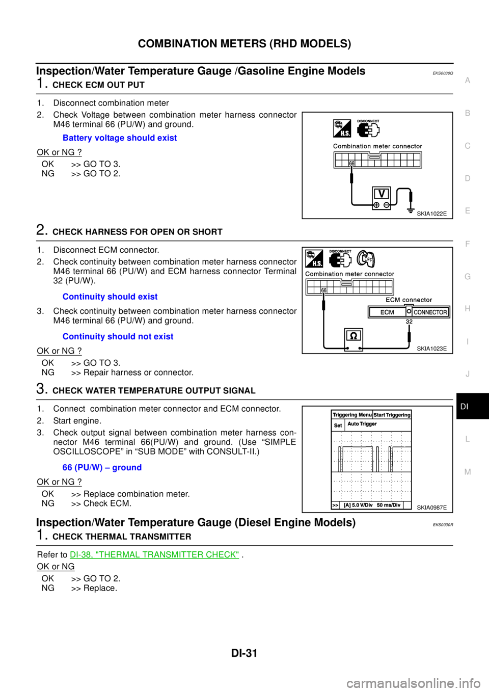
1.CHECK ECM OUT PUT
1. Disconnect combination meter
2. Check Voltage between combination meter harness connector
M46 terminal 66 (PU/W) and ground.
OK or NG ?
OK >> GO TO 3.
NG >> GO TO 2.
2.CHECK HARNESS FOR OPEN OR SHORT
1. Disconnect ECM connector.
2. Check continuity between combination meter harness connector
M46 terminal 66 (PU/W) and ECM harness connector Terminal
32 (PU/W).
3. Check continuity between combination meter harness connector
M46 terminal 66 (PU/W) and ground.
OK or NG ?
OK >> GO TO 3.
NG >> Repair harness or connector.
3.CHECK WATER TEMPERATURE OUTPUT SIGNAL
1. Connect combination meter connector and ECM connector.
2. Start engine.
3. Check output signal between combination meter harness con-
nector M46 terminal 66(PU/W) and ground. (Use “SIMPLE
OSCILLOSCOPE” in “SUB MODE” with CONSULT-II.)
OK or NG ?
OK >> Replace combination meter.
NG >> Check ECM.
Inspection/Water Temperature Gauge (Diesel Engine Models)EKS0030R
1.CHECK THERMAL TRANSMITTER
Refer toDI-38, "
THERMAL TRANSMITTER CHECK".
OK or NG
OK >> GO TO 2.
NG >> Replace.Battery voltage should exist
SKIA1022E
Continuity should exist
Continuity should not exist
SKIA1023E
66 (PU/W) – ground
SKIA0987E
Page 1110 of 3066
DI-56
WARNING CHIME
Symptom Chart
EKS002XQ
Power Supply and Ground Circuit CheckEKS002YF
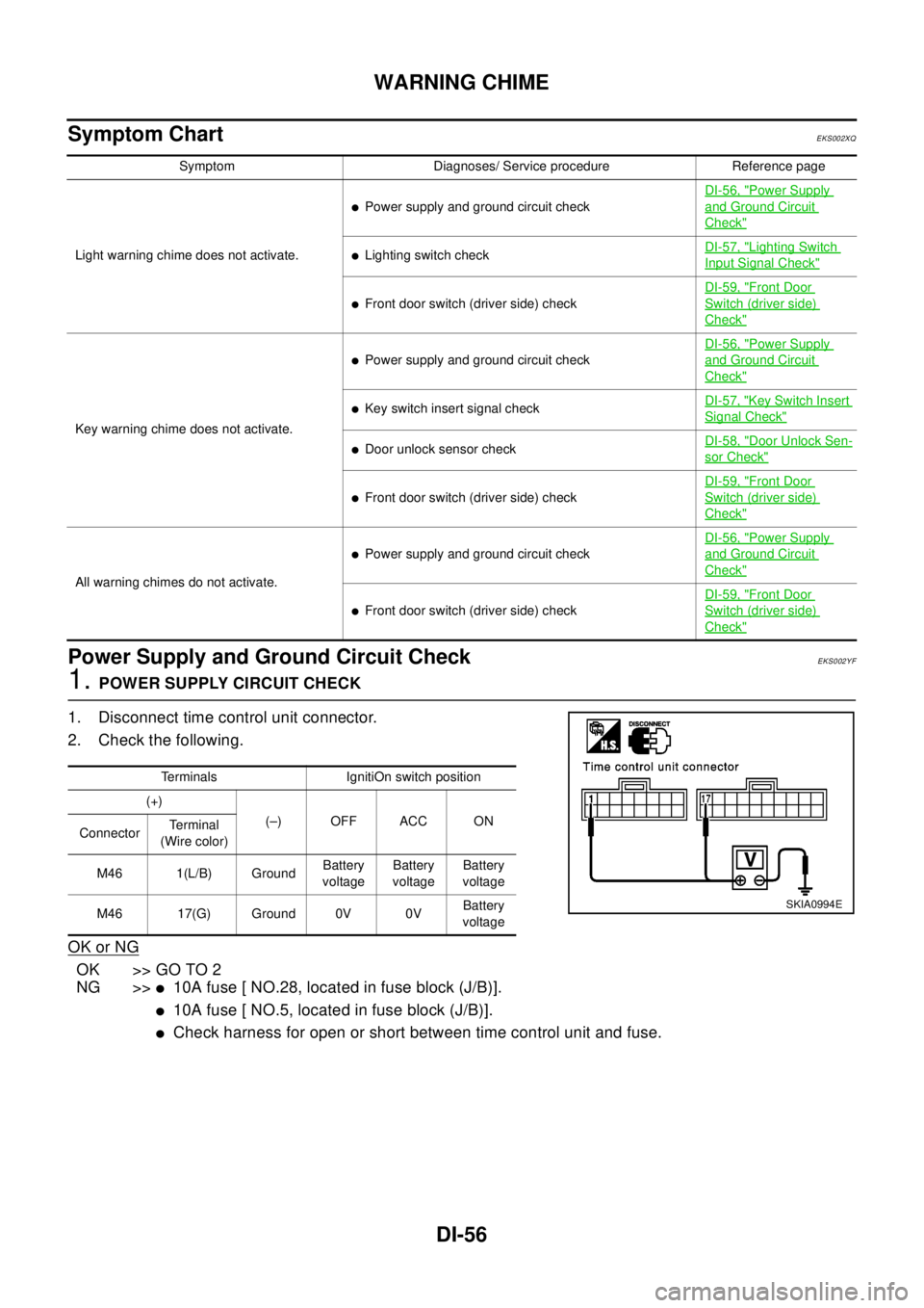
1.POWER SUPPLY CIRCUIT CHECK
1. Disconnect time control unit connector.
2. Check the following.
OK or NG
OK >> GO TO 2
NG >>
l10A fuse [ NO.28, located in fuse block (J/B)].
l10A fuse [ NO.5, located in fuse block (J/B)].
lCheck harness for open or short between time control unit and fuse.
Symptom Diagnoses/ Service procedure Reference page
Light warning chime does not activate.
lPower supply and ground circuit checkDI-56, "
Power Supply
and Ground Circuit
Check"
lLighting switch checkDI-57, "Lighting Switch
Input Signal Check"
lFront door switch (driver side) checkDI-59, "
Front Door
Switch (driver side)
Check"
Key warning chime does not activate.
lPower supply and ground circuit checkDI-56, "
Power Supply
and Ground Circuit
Check"
lKey switch insert signal checkDI-57, "Key Switch Insert
Signal Check"
lDoor unlock sensor checkDI-58, "Door Unlock Sen-
sor Check"
lFront door switch (driver side) checkDI-59, "
Front Door
Switch (driver side)
Check"
All warning chimes do not activate.
lPower supply and ground circuit checkDI-56, "
Power Supply
and Ground Circuit
Check"
lFront door switch (driver side) checkDI-59, "
Front Door
Switch (driver side)
Check"
Terminals IgnitiOn switch position
(+)
(–) OFF ACC ON
ConnectorTe r m i n a l
(Wire color)
M46 1(L/B) GroundBattery
voltageBattery
voltageBattery
voltage
M46 17(G) Ground 0V 0VBattery
voltage
SKIA0994E
Page 1124 of 3066

EC-10
DTC P0500 VEHICLESPEED SENSOR (VSS) .....744
Description ............................................................744
ECM Terminals and Reference Value ...................744
On Board Diagnosis Logic ....................................744
Overall Function Check ........................................744
Wiring Diagram .....................................................745
Diagnostic Procedure ...........................................747
DTC P1107 ABSOLUTE PRESSURE SENSOR ....749
Description ............................................................749
On Board Diagnosis Logic ....................................749
DTC Confirmation Procedure ...............................749
Diagnostic Procedure ...........................................749
DTC P1180 FUEL TEMPERATURE SENSOR .......751
Description ............................................................751
CONSULT-II Reference Value in Data Monitor Mode
.751
ECM Terminals and Reference Value ...................751
On Board Diagnosis Logic ....................................751
DTC Confirmation Procedure ...............................751
Wiring Diagram .....................................................752
Diagnostic Procedure ...........................................753
Removal and Installation ......................................753
DTC P1216 EDU .....................................................754
Description ............................................................754
ECM Terminals and Reference Value ...................754
On Board Diagnosis Logic ....................................755
DTC Confirmation Procedure ...............................755
Wiring Diagram .....................................................756
Diagnostic Procedure ...........................................758
Removal and Installation ......................................760
DTC P1217 OVERHEAT (COOLING SYSTEM) .....761
Description ............................................................761
CONSULT-II Reference Value in Data Monitor Mode
.761
ECM Terminals and Reference Value ...................761
On Board Diagnosis Logic ....................................761
Overall Function Check ........................................762
Wiring Diagram .....................................................763
Diagnostic Procedure ...........................................764
Main 12 Causes of Overheating ...........................770
Component Inspection ..........................................771
DTC P1233 - P1234 SUCTION CONTROL VALVE. 772
Description ............................................................772
CONSULT-II Reference Value in Data Monitor Mode
.772
ECM Terminals and Reference Value ...................772
On Board Diagnosis Logic ....................................773
DTC Confirmation Procedure ...............................773
Wiring Diagram .....................................................774
Diagnostic Procedure ...........................................775
Component Inspection ..........................................776
Removal and Installation ......................................776
DTC P1301 - P1304 FUEL INJECTOR ADJUST-
MENT RESISTOR ...................................................777
Description ............................................................777
ECM Terminals and Reference Value ...................777
On Board Diagnosis Logic ....................................777
DTC Confirmation Procedure ...............................777Wiring Diagram ..................................................... 778
Diagnostic Procedure ............................................ 779
Component Inspection .......................................... 780
Removal and Installation ....................................... 780
DTC P1305 FUEL LEAK ......................................... 781
On Board Diagnosis Logic .................................... 781
DTC Confirmation Procedure ................................ 781
Diagnostic Procedure ............................................ 781
Removal and Installation ....................................... 781
DTC P1510 ACCELERATOR PEDAL RELEASED
POSITION SWITCH ................................................. 783
Description ............................................................ 783
CONSULT-II Reference Value in Data Monitor Mode
. 783
ECM Terminals and Reference Value ................... 783
On Board Diagnosis Logic .................................... 784
DTC Confirmation Procedure ................................ 784
Wiring Diagram ..................................................... 785
Diagnostic Procedure ............................................ 786
Component Inspection .......................................... 787
Removal and Installation ....................................... 787
DTC P1606 ECM ..................................................... 788
Description ............................................................ 788
On Board Diagnosis Logic .................................... 788
DTC Confirmation Procedure ................................ 788
Diagnostic Procedure ............................................ 788
DTC P1621 ECM RELAY ........................................ 790
ECM Terminals and Reference valve .................... 790
On Board Diagnosis Logic .................................... 790
DTC Confirmation Procedure ................................ 790
Wiring Diagram ..................................................... 791
Diagnostic Procedure ............................................ 792
Component Inspection .......................................... 793
DTC P1660 BATTERY VOLTAGE ........................... 794
On Board Diagnosis Logic .................................... 794
DTC Confirmation Procedure ................................ 794
Diagnostic Procedure ............................................ 794
GLOW CONTROL SYSTEM ................................... 796
Description ............................................................ 796
ECM Terminals and Reference Value ................... 796
Wiring Diagram ..................................................... 797
Diagnostic Procedure ............................................ 798
Component Inspection .......................................... 802
Removal and Installation ....................................... 802
EGR VOLUME CONTROL SYSTEM ...................... 803
Description ............................................................ 803
CONSULT-II Reference Value in Data Monitor Mode
. 803
ECM Terminals and Reference Value ................... 804
Wiring Diagram ..................................................... 805
Diagnostic Procedure ............................................ 806
Component Inspection .......................................... 808
Removal and Installation ....................................... 809
BRAKE SWITCH ..................................................... 810
Description ............................................................ 810
ECM Terminals and Reference Value ................... 810
Wiring Diagram .....................................................811
Page 1130 of 3066
![NISSAN X-TRAIL 2003 Electronic Repair Manual EC-16
[QR (WITH EURO-OBD)]
PRECAUTIONS
PRECAUTIONS
PFP:00001
Precautions for Supplemental Restraint System (SRS) “AIR BAG” and “SEAT
BELT PRE-TENSIONER”
EBS00B0I
The Supplemental Restraint Sys](/img/5/57402/w960_57402-1129.png "NISSAN X-TRAIL 2003 Electronic Repair Manual EC-16
[QR (WITH EURO-OBD)]
PRECAUTIONS
PRECAUTIONS
PFP:00001
Precautions for Supplemental Restraint System (SRS) “AIR BAG” and “SEAT
BELT PRE-TENSIONER”
EBS00B0I
The Supplemental Restraint Sys")
EC-16
[QR (WITH EURO-OBD)]
PRECAUTIONS
PRECAUTIONS
PFP:00001
Precautions for Supplemental Restraint System (SRS) “AIR BAG” and “SEAT
BELT PRE-TENSIONER”
EBS00B0I
The Supplemental Restraint System such as “AIR BAG” and “SEAT BELT PRE-TENSIONER”, used along
with a front seat belt, helps to reduce the risk or severity of injury to the driver and front passenger for certain
types of collision. Information necessary to service the system safely is included in the SRS and SB section of
this Service Manual.
WAR NIN G:
lTo avoid rendering the SRS inoperative, which could increase the risk of personal injury or death
in the event of a collision which would result in air bag inflation, all maintenance must be per-
formed by an authorized NISSAN/INFINITI dealer.
lImproper maintenance, including incorrect removal and installation of the SRS, can lead to per-
sonal injury caused by unintentional activation of the system. For removal of Spiral Cable and Air
Bag Module, see the SRS section.
lDo not use electrical test equipment on any circuit related to the SRS unless instructed to in this
Service Manual. SRS wiring harnesses can be identified by yellow harness connectors.
On Board Diagnostic (OBD) System of Engine and A/TEBS00B0J
The ECM has an on board diagnostic system. It will light up the malfunction indicator (MI) to warn the driver of
a malfunction causing emission deterioration.
CAUTION:
lBe sure to turn the ignition switch OFF and disconnect the negative battery terminal before any
repair or inspection work. The open/short circuit of related switches, sensors, solenoid valves,
etc. will cause the MI to light up.
lBe sure to connect and lock the connectors securely after work. A loose (unlocked) connector will
cause the MI to light up due to the open circuit. (Be sure the connector is free from water, grease,
dirt, bent terminals, etc.)
lCertain systems and components, especially those related to OBD, may use a new style slide-
locking type harness connector. For description and how to disconnect, refer toPG-70, "
HAR-
NESS CONNECTOR".
lBe sure to route and secure the harnesses properly after work. The interference of the harness
with a bracket, etc. may cause the MI to light up due to the short circuit.
lBe sure to connect rubber tubes properly after work. A misconnected or disconnected rubber tube
may cause the MI to light up due to the malfunction of the fuel injection system, etc.
lBe sure to erase the unnecessary malfunction information (repairs completed) from the ECM and
TCM (Transmission control module) before returning the vehicle to the customer.
PrecautionEBS00B0K
lAlways use a 12 volt battery as power source.
lDo not attempt to disconnect battery cables while engine is
running.
lBefore connecting or disconnecting the ECM harness con-
nector, turn ignition switch OFF and disconnect negative
battery terminal. Failure to do so may damage the ECM
because battery voltage is applied to ECM even if ignition
switch is turned off.
lBefore removing parts, turn ignition switch OFF and then
disconnect battery ground cable.
SEF289H
Page 1131 of 3066
![NISSAN X-TRAIL 2003 Electronic Repair Manual PRECAUTIONS
EC-17
[QR (WITH EURO-OBD)]
C
D
E
F
G
H
I
J
K
L
MA
EC
lDo not disassemble ECM.
lIf a battery terminal is disconnected, the memory will return
to the ECM value.
The ECM will now start to sel](/img/5/57402/w960_57402-1130.png "NISSAN X-TRAIL 2003 Electronic Repair Manual PRECAUTIONS
EC-17
[QR (WITH EURO-OBD)]
C
D
E
F
G
H
I
J
K
L
MA
EC
lDo not disassemble ECM.
lIf a battery terminal is disconnected, the memory will return
to the ECM value.
The ECM will now start to sel")
PRECAUTIONS
EC-17
[QR (WITH EURO-OBD)]
C
D
E
F
G
H
I
J
K
L
MA
EC
lDo not disassemble ECM.
lIf a battery terminal is disconnected, the memory will return
to the ECM value.
The ECM will now start to self-control at its initial value.
Engine operation can vary slightly when the terminal is dis-
connected. However, this is not an indication of a problem.
Do not replace parts because of a slight variation.
lWhen connecting ECM harness connector, fasten it
securely with a lever as far as it will go as shown at right.
lWhen connecting or disconnecting pin connectors into or
from ECM, take care not to damage pin terminals (bend or
break).
Make sure that there are not any bends or breaks on ECM
pin terminal, when connecting pin connectors.
lSecurely connect ECM harness connectors.
A poor connection can cause an extremely high (surge)
voltage to develop in coil and condenser, thus resulting in
damage to ICs.
lKeep engine control system harness at least 10 cm (4 in)
away from adjacent harness, to prevent engine control sys-
tem malfunctions due to receiving external noise, degraded
operation of ICs, etc.
lKeep engine control system parts and harness dry.
lBefore replacing ECM, perform “ECM Terminals and Refer-
ence Value” inspection and make sure ECM functions prop-
erly. Refer toEC-79
.
lHandle mass air flow sensor carefully to avoid damage.
lDo not disassemble mass air flow sensor.
lDo not clean mass air flow sensor with any type of deter-
gent.
lDo not disassemble electric throttle control actuator.
lEven a slight leak in the air intake system can cause seri-
ous problems.
lDo not shock or jar the camshaft position sensor (PHASE),
crankshaft position sensor (POS).
SEF707Y
SEF908W
PBIB0090E
MEF040D
Page 1138 of 3066
![NISSAN X-TRAIL 2003 Electronic Repair Manual EC-24
[QR (WITH EURO-OBD)]
ENGINE CONTROL SYSTEM
System Chart
EBS00B0Q
*1: This sensor is not used to control the engine system under normal conditions.
*2: These signals are sent to the ECM through C](/img/5/57402/w960_57402-1137.png "NISSAN X-TRAIL 2003 Electronic Repair Manual EC-24
[QR (WITH EURO-OBD)]
ENGINE CONTROL SYSTEM
System Chart
EBS00B0Q
*1: This sensor is not used to control the engine system under normal conditions.
*2: These signals are sent to the ECM through C")
EC-24
[QR (WITH EURO-OBD)]
ENGINE CONTROL SYSTEM
System Chart
EBS00B0Q
*1: This sensor is not used to control the engine system under normal conditions.
*2: These signals are sent to the ECM through CAN communication line.
Multiport Fuel Injection (MFI) SystemEBS00B0R
INPUT/OUTPUT SIGNAL CHART
*1: Under normal conditions, this sensor is not for engine control operation.
*2: This signal is sent to the ECM through CAN communication line.Input (Sensor) ECM Function Output (Actuator)
lCamshaft position sensor (PHASE)
lCrankshaft position sensor (POS)
lMass air flow sensor
lEngine coolant temperature sensor
lHeated oxygen sensor 1
lThrottle position sensor
lAccelerator pedal position sensor
lPark/neutral position (PNP) switch
lIntake air temperature sensor
lPower steering pressure sensor
lIgnition switch
lBattery voltage
lKnock sensor
lRefrigerant pressure sensor
lHeated oxygen sensor 2 *1
lTCM (Transmission control module) *2
lESP/TCS/ABS control unit *2
lWheel sensor
lAir conditioner switch
lElectrical loadFuel injection & mixture ratio control Fuel injectors
Electronic ignition system Power transistors
Fuel pump control Fuel pump relay
On board diagnostic system MI (On the instrument panel)
Heated oxygen sensor 1 heater control Heated oxygen sensor 1 heater
Heated oxygen sensor 2 heater control Heated oxygen sensor 2 heater
EVAP canister purge flow controlEVAP canister purge volume control
solenoid valve
Air conditioning cut control Air conditioner relay
Cooling fan control Cooling fan relays
Sensor Input Signal to ECMECM func-
tionActuator
Crankshaft position sensor (POS)
Engine speed
Piston position
Fuel injec-
tion & mix-
ture ratio
controlFuel injectors Camshaft position sensor (PHASE)
Mass air flow sensor Amount of intake air
Engine coolant temperature sensor Engine coolant temperature
Heated oxygen sensor 1 Density of oxygen in exhaust gas
Throttle position sensor Throttle position
Accelerator pedal position sensor Accelerator pedal position
Park/neutral position (PNP) switch Gear position
Ignition switch Start signal
Knock sensor Engine knocking condition
Battery Battery voltage
Power steering pressure sensor Power steering operation
Heated oxygen sensor 2 *1 Density of oxygen in exhaust gas
ESP/TCS/ABS control unit *2 ESP/TCS operation command
Wheel sensor Vehicle speed
Air conditioner switch Air conditioner operation
Page 1141 of 3066
![NISSAN X-TRAIL 2003 Electronic Repair Manual ENGINE CONTROL SYSTEM
EC-27
[QR (WITH EURO-OBD)]
C
D
E
F
G
H
I
J
K
L
MA
EC
Electronic Ignition (EI) SystemEBS00B0S
INPUT/OUTPUT SIGNAL CHART
SYSTEM DESCRIPTION
The ignition timing is controlled by the](/img/5/57402/w960_57402-1140.png "NISSAN X-TRAIL 2003 Electronic Repair Manual ENGINE CONTROL SYSTEM
EC-27
[QR (WITH EURO-OBD)]
C
D
E
F
G
H
I
J
K
L
MA
EC
Electronic Ignition (EI) SystemEBS00B0S
INPUT/OUTPUT SIGNAL CHART
SYSTEM DESCRIPTION
The ignition timing is controlled by the")
ENGINE CONTROL SYSTEM
EC-27
[QR (WITH EURO-OBD)]
C
D
E
F
G
H
I
J
K
L
MA
EC
Electronic Ignition (EI) SystemEBS00B0S
INPUT/OUTPUT SIGNAL CHART
SYSTEM DESCRIPTION
The ignition timing is controlled by the ECM to maintain the best air-
fuel ratio for every running condition of the engine. The ignition tim-
ing data is stored in the ECM. This data forms the map shown.
The ECM receives information such as the injection pulse width and
camshaft position sensor signal. Computing this information, ignition
signals are transmitted to the power transistor.
e.g.,N:1,800rpm,Tp:1.50msec
A°BTDC
During the following conditions, the ignition timing is revised by the
ECM according to the other data stored in the ECM.
lAt starting
lDuring warm-up
lAt idle
lAt low battery voltage
lDuring acceleration
The knock sensor retard system is designed only for emergencies. The basic ignition timing is programmed
within the anti-knocking zone, if recommended fuel is used under dry conditions. The retard system does not
operate under normal driving conditions. If engine knocking occurs, the knock sensor monitors the condition.
The signal is transmitted to the ECM. The ECM retards the ignition timing to eliminate the knocking condition.
Air Conditioning Cut ControlEBS00B0T
INPUT/OUTPUT SIGNAL CHART
SYSTEM DESCRIPTION
This system improves engine operation when the air conditioner is used.
Under the following conditions, the air conditioner is turned off.
Sensor Input Signal to ECMECM func-
tionActuator
Crankshaft position sensor (POS)
Engine speed
Piston position
Ignition
timing con-
trolPower transistor Camshaft position sensor (PHASE)
Mass air flow sensor Amount of intake air
Engine coolant temperature sensor Engine coolant temperature
Throttle position sensor Throttle position
Accelerator pedal position sensor Accelerator pedal position
Ignition switch Start signal
Knock sensor Engine knocking
Park/neutral position (PNP) switch Gear position
Battery Battery voltage
Wheel sensor Vehicle speed
SEF742M
Sensor Input Signal to ECM ECM function Actuator
Air conditioner switch Air conditioner “ON” signal
Air conditioner
cut controlAir conditioner relay Throttle position sensor Throttle valve opening angle
Crankshaft position sensor (POS) Engine speed
Engine coolant temperature sensor Engine coolant temperature
Ignition switch Start signal
Refrigerant pressure sensor Refrigerant pressure
Power steering pressure sensor Power steering operation
Wheel sensor Vehicle speed
Page 1146 of 3066
![NISSAN X-TRAIL 2003 Electronic Repair Manual EC-32
[QR (WITH EURO-OBD)]
BASIC SERVICE PROCEDURE
PREPARATION
Before performing “Idle Air Volume Learning”, make sure that all of the following conditions are satisfied.
Learning will be cancelle](/img/5/57402/w960_57402-1145.png "NISSAN X-TRAIL 2003 Electronic Repair Manual EC-32
[QR (WITH EURO-OBD)]
BASIC SERVICE PROCEDURE
PREPARATION
Before performing “Idle Air Volume Learning”, make sure that all of the following conditions are satisfied.
Learning will be cancelle")
EC-32
[QR (WITH EURO-OBD)]
BASIC SERVICE PROCEDURE
PREPARATION
Before performing “Idle Air Volume Learning”, make sure that all of the following conditions are satisfied.
Learning will be cancelled if any of the following conditions are missed for even a moment.
lBattery voltage: More than 12.9V (At idle)
lEngine coolant temperature: 70 - 100°C (158 - 212°F)
lPNP switch: ON
lElectric load switch: OFF
(Air conditioner, headlamp, rear window defogger)
On vehicles equipped with daytime light systems, set lighting switch to the 1st position to light
only small lamps.
lSteering wheel: Neutral (Straight-ahead position)
lVehicle speed: Stopped
lTransmission: Warmed-up
For A/T models with CONSULT-II, drive vehicle until “FLUID TEMP SE” in “DATA MONITOR” mode of “A/
T” system indicates less than 0.9V.
For A/T models without CONSULT-II and M/T models, drive vehicle for 10 minutes.
OPERATION PROCEDURE
With CONSULT-II
1. PerformEC-31, "Accelerator Pedal Released Position Learning".
2. PerformEC-31, "
Throttle Valve Closed Position Learning".
3. Start engine and warm it up to normal operating temperature.
4. Check that all items listed under the topic “PRE-CONDITIONING” (previously mentioned) are in good
order.
5. Select “IDLE AIR VOL LEARN” in “WORK SUPPORT” mode.
6. Touch “START” and wait 20 seconds.
SEF452Y
SEF454Y
Page 1161 of 3066
![NISSAN X-TRAIL 2003 Electronic Repair Manual ON BOARD DIAGNOSTIC (OBD) SYSTEM
EC-47
[QR (WITH EURO-OBD)]
C
D
E
F
G
H
I
J
K
L
MA
EC
7. Touch “ERASE”. (The DTC in the ECM will be erased.)
How to Erase DTC ( With GST)
The emission related diagn](/img/5/57402/w960_57402-1160.png "NISSAN X-TRAIL 2003 Electronic Repair Manual ON BOARD DIAGNOSTIC (OBD) SYSTEM
EC-47
[QR (WITH EURO-OBD)]
C
D
E
F
G
H
I
J
K
L
MA
EC
7. Touch “ERASE”. (The DTC in the ECM will be erased.)
How to Erase DTC ( With GST)
The emission related diagn")
ON BOARD DIAGNOSTIC (OBD) SYSTEM
EC-47
[QR (WITH EURO-OBD)]
C
D
E
F
G
H
I
J
K
L
MA
EC
7. Touch “ERASE”. (The DTC in the ECM will be erased.)
How to Erase DTC ( With GST)
The emission related diagnostic information in the ECM can be erased by selecting Mode 4 with GST.
NOTE:
If the DTC is not for A/T related items (seeEC-12
),skipstep2.
1. If the ignition switch stays “ON” after repair work, be sure to turn ignition switch “OFF” once. Wait at least
10 seconds and then turn it “ON” (engine stopped) again.
2. Perform “SELF-DIAGNOSTIC PROCEDURE (Without CONSULT-II)” in AT section titled “TROUBLE
DIAGNOSIS”, “Self-diagnosis”. (The engine warm-up step can be skipped when performing the diagnosis
only to erase the DTC.)
3. Select Mode 4 with GST (Generic Scan Tool).
How to Erase DTC ( No Tools)
1. If the ignition switch stays "ON" after repair work, be sure to turn ignition switch "OFF" once.
2. Wait at least 10 seconds and then turn it "ON" (engine stopped) again.
3. Change the diagnostic test mode from Mode II to Mode I by depressing the accelerator pedal. Refer to
EC-49, "
HOW TO SWITCH DIAGNOSTIC TEST MODE".
lIf the battery is disconnected, the emission-related diagnostic information will be lost after
approx. 24 hours.
lThe following data are cleared when the ECM memory is erased.
1. Diagnostic trouble codes
2. 1st trip diagnostic trouble codes
3. Freeze frame data
4. 1st trip freeze frame data
SEF966X