battery NISSAN X-TRAIL 2003 Electronic Manual Online
[x] Cancel search | Manufacturer: NISSAN, Model Year: 2003, Model line: X-TRAIL, Model: NISSAN X-TRAIL 2003Pages: 3066, PDF Size: 51.47 MB
Page 830 of 3066
BL-86
NATS (NISSAN ANTI-THEFT SYSTEM)
2.CHECK SECURITY INDICATOR LAMP
1. Install 10A fuse.
2. Perform initialization with CONSULT-II.
For initialization, refer to “CONSULT-II Operation Manual NATS”.
3. Turn ignition switch OFF.
4. Start engine and turn ignition switch OFF.
5. Check the security indicator lamp lighting.
Security indicator lamp should be light up.
OK or NG?
OK >> INSPECTION END
NG >> GO TO 3
3.CHECK SECURITY INDICATOR LAMP POWER SUPPLY CIRCUIT
1. Disconnect security indicator lamp connector.
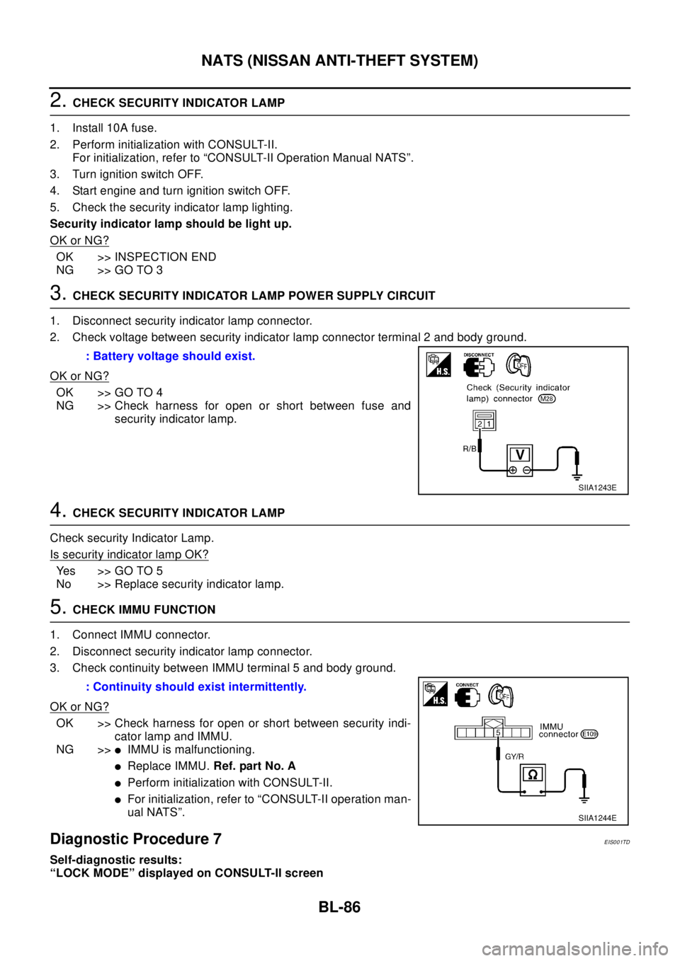
2. Check voltage between security indicator lamp connector terminal 2 and body ground.
OK or NG?
OK >> GO TO 4
NG >> Check harness for open or short between fuse and
security indicator lamp.
4.CHECK SECURITY INDICATOR LAMP
Check security Indicator Lamp.
Is security indicator lamp OK?
Yes >>GOTO5
No >> Replace security indicator lamp.
5.CHECK IMMU FUNCTION
1. Connect IMMU connector.
2. Disconnect security indicator lamp connector.
3. Check continuity between IMMU terminal 5 and body ground.
OK or NG?
OK >> Check harness for open or short between security indi-
cator lamp and IMMU.
NG >>
lIMMU is malfunctioning.
lReplace IMMU.Ref. part No. A
lPerform initialization with CONSULT-II.
lFor initialization, refer to “CONSULT-II operation man-
ual NATS”.
Diagnostic Procedure 7EIS001TD
Self-diagnostic results:
“LOCK MODE” displayed on CONSULT-II screen: Battery voltage should exist.
SIIA1243E
: Continuity should exist intermittently.
SIIA1244E
Page 837 of 3066
PRECAUTIONS
BR-3
C
D
E
G
H
I
J
K
L
MA
B
BR
PRECAUTIONSPFP:00001
Precautions for Models with SRS Air Bag and Pre-Tensioner Seat BeltEFS000BY
WA RN ING:
lBefore removing and installing components and harnesses of SRS air bag and seat belt pre-ten-
sioner system, turn ignition switch OFF, disconnect battery ground cable, and wait at least 3 min-
utes. (This discharges electricity held in the air bag sensor unit's additional power circuit.)
lDo not use pneumatic or electric tools to remove and install the components.
lDo not solder SRS air bag and seat belt pre-tensioner system harnesses when making repairs.
Make sure harness is not pinched and there is no contact with other components.
lWhen checking the SRS air bag and the seat belt pre-tensioner circuit or the components of each
system, do not use an electric tester such as a circuit tester. (This is to prevent accidental trigger-
ing caused by the weak electric current of a tester.)
lNever insert foreign material (such as a screwdriver) in the air bag module and pre-tensioner seat
belt connectors. (The units may be actuated by mistake by static electricity.)
lSeat belt pre-tensioner and SRS air bag harnesses can be distinguished from other harnesses by
their yellow connectors.
lWhen servicing, refer to “SB Seat Belt” and “SRS Air Bag” for safety.
Precautions for Brake SystemEFS000BZ
lClean dust on brake pads, shoes, drums, and back plates with a vacuum dust collector. Do not blow with
compressed air.
lRecommended fluid is brake fluid “DOT 3” or “DOT 4”.
lNever reuse drained brake fluid.
lBe careful not to splash brake fluid on painted areas such as the body. If brake fluid is splashed or spilled
on paint, wipe it off and flush the area with water immediately.
lUse only clean brake fluid when cleaning master cylinder and disc brake components.
lNever use mineral oils such as gasoline or kerosene to clean. They will ruin the rubber parts and cause
improper operation.
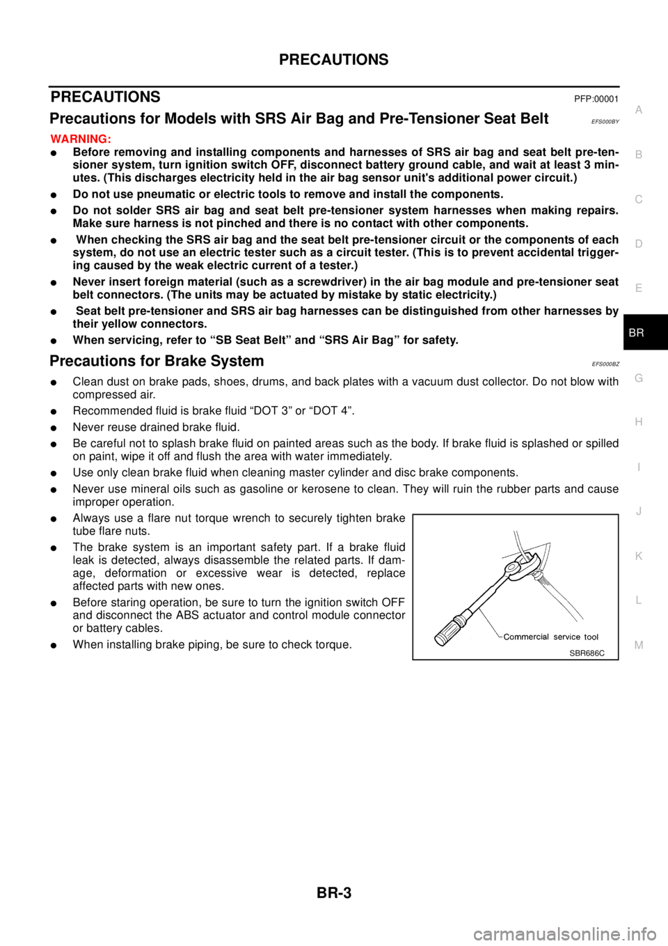
lAlways use a flare nut torque wrench to securely tighten brake
tube flare nuts.
lThe brake system is an important safety part. If a brake fluid
leak is detected, always disassemble the related parts. If dam-
age, deformation or excessive wear is detected, replace
affected parts with new ones.
lBefore staring operation, be sure to turn the ignition switch OFF
and disconnect the ABS actuator and control module connector
or battery cables.
lWhen installing brake piping, be sure to check torque.SBR686C
Page 872 of 3066
![NISSAN X-TRAIL 2003 Electronic Manual Online BRC-4
[4WD/ABS]
PRECAUTIONS
[4WD/ABS]PRECAUTIONSPFP:00001
Precautions for brake systemEFS001B6
lRecommended fluid is brake fluid “DOT 3 ”or “DOT 4”.
lNever reuse drained brake fluid.
lBe caref](/img/5/57402/w960_57402-871.png "NISSAN X-TRAIL 2003 Electronic Manual Online BRC-4
[4WD/ABS]
PRECAUTIONS
[4WD/ABS]PRECAUTIONSPFP:00001
Precautions for brake systemEFS001B6
lRecommended fluid is brake fluid “DOT 3 ”or “DOT 4”.
lNever reuse drained brake fluid.
lBe caref")
BRC-4
[4WD/ABS]
PRECAUTIONS
[4WD/ABS]PRECAUTIONSPFP:00001
Precautions for brake systemEFS001B6
lRecommended fluid is brake fluid “DOT 3 ”or “DOT 4”.
lNever reuse drained brake fluid.
lBe careful not to splash brake fluid on painted areas.
lTo clean or wash all parts of master cylinder, disc brake caliper and wheel cylinder, use clean brake fluid.
lNever use mineral oils such as gasoline or kerosene. They will ruin rubber parts of the hydraulic system.
lUse flare nut wrench when removing and installing brake tube.
lAlways torque brake lines when installing.
lBurnish the brake contact surfaces after refinishing or replacing
drums or rotors, after replacing pads or linings, or if a soft pedal
occurs at very low mileage. Refer toBR-10, "
Brake Burnishing
Procedure".
lBefore working, turn OFF ignition switch. Disconnect connectors
for ABS actuator and control module or battery terminals.
WAR NIN G:
lClean brake pads and shoes with a waste cloth, then wipe
with a dust collector.
Precautions for brake controlEFS001B7
lIf malfunction is indicated by 4WD warning lamp and/or ABS warning lamp, collect necessary information
from customer (what symptoms are present under what conditions). Find out possible causes before start-
ing service. Besides electrical system inspection, check operation of ABS actuator.
lIf malfunction is detected, proceed to trouble diagnosis after checking tire pressure and tire wear.
lStopping distance or steering stability may be deteriorated by the following conditions. Tire size and type
are in improper combination. Brake pads are not Nissan genuine parts.
lFitting tires of different size on vehicle can be cause of longitudinal vibration. Always use tires of the same
size and brand. Exchange front and rear tires on the following conditions: Longitudinal vibration occurs in
vehicle with tires of the same size and brand. After replacement, perform trouble diagnosis. 1580|None
l4WD/ABS function may have a failure or error under following condition: There is radio, antenna, or
antenna lead-in wire (including wiring) near control module.
lIf aftermarket parts (e.g. Car stereo equipment, CD player) have been installed, check electrical har-
nesses for pinches, open, and improper wiring.
SBR686C
Page 887 of 3066
![NISSAN X-TRAIL 2003 Electronic Manual Online TROUBLE DIAGNOSIS
BRC-19
[4WD/ABS]
C
D
E
G
H
I
J
K
L
MA
B
BRC
CAUTION:
1. Light tight-corner braking symptom may occur depending on driving conditions in AUTO mode.
This is not malfunction.
2. Heavy t](/img/5/57402/w960_57402-886.png "NISSAN X-TRAIL 2003 Electronic Manual Online TROUBLE DIAGNOSIS
BRC-19
[4WD/ABS]
C
D
E
G
H
I
J
K
L
MA
B
BRC
CAUTION:
1. Light tight-corner braking symptom may occur depending on driving conditions in AUTO mode.
This is not malfunction.
2. Heavy t")
TROUBLE DIAGNOSIS
BRC-19
[4WD/ABS]
C
D
E
G
H
I
J
K
L
MA
B
BRC
CAUTION:
1. Light tight-corner braking symptom may occur depending on driving conditions in AUTO mode.
This is not malfunction.
2. Heavy tight-corner braking symptom occurs when vehicle is driven in the following conditions:
LOCK mode, steering wheel is turned fully to either sides, and accelerator pedal was depressed.
4WD/ABS Control Unit Input/Output Signal StandardEFS001BG
4WD/ABS CONTROL UINT CONNECTOR TERMINAL ARRANGEMENT
CAUTION:
When ignition switch is turned to ON with connectors of 4WD/ABS control unit and actuator con-
nected.
REFERENCE STANDARD TABLE
Specifications defined by circuit tester
Vehicle running, 4WD warning lamp
flashes slowly. (When it flashes for
Approx. One minute, then does not illu-
minate.)Slow flashing: One flashing
per 2 secondslEngine run-
ning
lDriving at
vehicle speed
30km/hTire size is different for front and rear of vehicle.BRC-45
Vehicle does not enter 4WD mode
even though 4WD warning lamp is off.Engine runningMechanical malfunction of electronically con-
trolled coupling (Mechanical engagement of
clutch is not possible.)BRC-46
Symptom Condition Check items Reference page
SFIA0351E
Terminal No.
Location Standard (note 1)(Note) Check
points when result
was malfunctioning +-
3.
109Power supply Ignition switch ONBattery voltage (Approx.
12V)Control unit power
supply circuit
Page 888 of 3066
![NISSAN X-TRAIL 2003 Electronic Manual Online BRC-20
[4WD/ABS]
TROUBLE DIAGNOSIS
11 5
Body
groundGround -Control unit ground
path 11 3
111
108
106
104
13 Stop lamp signalDepress the brake pedal.
Release brake pedal.Battery voltage (Approx.
12V)
A](/img/5/57402/w960_57402-887.png "NISSAN X-TRAIL 2003 Electronic Manual Online BRC-20
[4WD/ABS]
TROUBLE DIAGNOSIS
11 5
Body
groundGround -Control unit ground
path 11 3
111
108
106
104
13 Stop lamp signalDepress the brake pedal.
Release brake pedal.Battery voltage (Approx.
12V)
A")
BRC-20
[4WD/ABS]
TROUBLE DIAGNOSIS
11 5
Body
groundGround -Control unit ground
path 11 3
111
108
106
104
13 Stop lamp signalDepress the brake pedal.
Release brake pedal.Battery voltage (Approx.
12V)
Approx. 0VStop lamp switch
and path
5ABS MOTOR
RELAYABS motor actuated
(byactivetestmodeofCONSULT)
ABS motor stopped (Ignition switch is in
ON)Approx. 2 V or less
Battery voltage (Approx.
12V)ABS motor, motor
relay and harness
17ABS ACTUATOR
RELAYWhen actuator relay is active.
(the engine running)
When actuator relay is inactive.
(In fail-safe mode, before starting
engine)Approx. 2 V or less
Battery voltage (Approx.
12V)ABS actuator relay
and harness
11 6Front RH wheel IN
solenoid
Actuator is activated (by active test
mode of CONSULT) or actuator relay is
not activated
(In fail-safe mode, before starting
engine)
Actuator is not activated and actuator
relay is activated (Vehicle stopped with
engine running)Approx. 0V
Battery voltage (Approx.
12V)ABS solenoid valve
path 11 4Front RH wheel
OUT solenoid
11 2Front LH wheel IN
solenoid
11 0Front LH wheel
OUT solenoid
107Rear RH wheel IN
solenoid
105Rear RH wheel
OUT solenoid
103Rear LH wheel IN
solenoid
101Rear LH wheel
OUT solenoid
74WD warning lamp
(Note 2)4WD warning lamp ON
4WD warning lamp OFFApprox. 0V
Battery voltage (Approx.
12V)4WD warning lamp
and harness
4ABS warning lamp
(Note 3)ABS warning lamp ON
ABS warning lamp OFFApprox. 0V
Battery voltage (Approx.
12V)ABS warning lamp
and path
16AUTO indicator
lampAUTO indicator lamp ON
AUTO indicator lamp OFFApprox. 0V
Battery voltage (Approx.
12V)AUTO indicator
lamp and harness
6LOCK indicator
lampLOCK indicator lamp ON
LOCK indicator lamp OFFApprox. 0V
Battery voltage (Approx.
12V)LOCK indicator
lamp and harness
46 37 FR RH SENSOR
At vehicle rotating (Approx. 30km/h)Pulse generation
Approx. 200HzSpeed sensor and
harness 34 43FR LH SENSOR
[OPEN]
36 45 RR RH SENSOR
44 35 RR LH SENSOR Te r m i n a l N o .
Location Standard (note 1)(Note) Check
points when result
was malfunctioning +-
Page 889 of 3066
![NISSAN X-TRAIL 2003 Electronic Manual Online TROUBLE DIAGNOSIS
BRC-21
[4WD/ABS]
C
D
E
G
H
I
J
K
L
MA
B
BRC
CAUTION:
1. If a circuit tester for measuring voltage is used for the check, do not forcibly extend any connector
terminals.
CAUTION:
2. 4](/img/5/57402/w960_57402-888.png "NISSAN X-TRAIL 2003 Electronic Manual Online TROUBLE DIAGNOSIS
BRC-21
[4WD/ABS]
C
D
E
G
H
I
J
K
L
MA
B
BRC
CAUTION:
1. If a circuit tester for measuring voltage is used for the check, do not forcibly extend any connector
terminals.
CAUTION:
2. 4")
TROUBLE DIAGNOSIS
BRC-21
[4WD/ABS]
C
D
E
G
H
I
J
K
L
MA
B
BRC
CAUTION:
1. If a circuit tester for measuring voltage is used for the check, do not forcibly extend any connector
terminals.
CAUTION:
2. 4WD warning lamp ON/OFF timing
CAUTION:
3. ABS warning lamp ON/OFF timing
CAUTION:
4. Unit name is indicated by the name used in circuit diagram (4WD solenoid valve). However, it is “E-
TS solenoid” in CONSULT-II data.
Specifications defined by CONSULT
102
Body ground
4WD solenoid valve
(E-TS solenoid
valve)At vehicle stop engine idlingBattery voltage (Approx.
12V)4WD actuator relay
solenoid valve and
harness
18 4WD actuator relay At vehicle stop engine idling 2 V or lower4WD actuator relay
and harness
2
4G - sensor power
supply
At ignition switch ON (vehicle horizontal
stop condition)Approx. 8 V
G -sensor and har-
ness
32Longitudinal G -
sensorApprox. 2.5V
41 G -sensor ground Approx. 0V
22Throttle position
sensorWide open throttle
Closed throttleApprox. 4.0 V
Approx. 0.5 VThrottle position
sensor and har-
ness
24Parking brake
switchIn parking position
In other than parking position-Parking brake
switch and harness
26Drive mode
change-over switch
AUTODrive mode change-over switch: 2WD
Drive mode change-over switch: other
than 2WDSW ON: Approx. 0 V
SW OFF: Approx. 5 VDrive mode
change-over switch
and path
27Drive mode
change-over switch
LOCKDrive mode change-over switch: LOCK
Drive mode change-over switch: other
than LOCKSW ON: Approx. 0 V
SW OFF: Approx. 5 VDrive mode
change-over switch
and path
ON: When ignition switch is turned ON (before engine starts) or when malfunction is
detected
OFF: After engine is started (When the system is in normal condition)
ON: When ignition switch is turned ON (before engine starts) or when malfunction is
detected
OFF: After engine is started (When the system is in normal condition)
Terminal No.
Location Standard (note 1)(Note) Check
points when result
was malfunctioning +-
Items to be monitored ContentsData monitor
(Reference)
Check points when result
was malfunctioning ConditionReference values in
normal operation
Wheel speed sensor
FR,
FL, RR, RL (km/h)Vehicle wheel speedWhen the vehicle is
stopped0km/h
Wheel speed sensor and
harness
While driving (note:1)Almost in accordance
with speedometer dis-
play (within±10%)
LONGITUDINAL G-
SENSOR (4WD mod-
els)G -sensor operating
conditionWith vehicle stopped
on flat road.plus; 0.15 G G -sensor and harness
Page 890 of 3066
![NISSAN X-TRAIL 2003 Electronic Manual Online BRC-22
[4WD/ABS]
TROUBLE DIAGNOSIS
Throttle position sen-
sor [V]Throttle valve open/
close conditionClosed throttle to wide
open throttleWhen closed throttle:
Approx. 0.5V
Throttle position sensor
an](/img/5/57402/w960_57402-889.png "NISSAN X-TRAIL 2003 Electronic Manual Online BRC-22
[4WD/ABS]
TROUBLE DIAGNOSIS
Throttle position sen-
sor [V]Throttle valve open/
close conditionClosed throttle to wide
open throttleWhen closed throttle:
Approx. 0.5V
Throttle position sensor
an")
BRC-22
[4WD/ABS]
TROUBLE DIAGNOSIS
Throttle position sen-
sor [V]Throttle valve open/
close conditionClosed throttle to wide
open throttleWhen closed throttle:
Approx. 0.5V
Throttle position sensor
and harness
When wide open throt-
tle: Approx. 4.0 V
Stop lamp switch Brake pedal statusDepress the brake
pedal.ON
Stop lamp switch and path
Release brake pedal. OFF
ENGINE RPM SIG-
NAL [STOP/RUN]With engine runningEngine RPM below
400 rpmSTOP
Engine RPM signal path
Engine RPM 400 rpm
or higherRUN
ABS inlet S/V
FR, FL, RR, RL (ON/
OFF)
Solenoid valve opera-
tionActuator (solenoid
valve) is activated (by
active test mode of
CONSULT) or actua-
tor relay is not acti-
vated (in fail-safe
mode, before starting
engine)ON
ABS solenoid valve path
ABS outlet S/V
FR, FL, RR, RL (ON/
OFF)Actuator (solenoid
valve) is not activated
and actuator relay is
activated (vehicle
stopped with (Engine
running)OFF
E-TS solenoid valve
(A)
(4WD solenoid valve)4WD solenoid valve
current supply moni-
toring conditionIn LOCK mode, at
starting vehicle (when
accelerator pedal was
depressed)Approx. 2.8 AE-TS solenoid valve (4WD
solenoid valve) and har-
ness
ABS actuator relay
(ON/OFF)Actuator relay acti-
vatedVehicle stopped
Ignition switch ONOFF
ABS actuator relay and
harness
Vehicle stopped
Engine runningON
ABS motor relay (ON/
OFF)Motor relay and motor
activated(Ignition switch ON or
engine is running):
ABS inactiveOFF
ABS motor and motor relay
harness
(Ignition switch ON or
engine is running):
ABS activeON
E-TS actuator relay
(4WD actuator relay)
(ON/OFF)E-TS actuator relay
(4WD actuator relay)
activation conditionVehicle stopped (Igni-
tion switch ON)OFFE-TS actuator relay (4WD
actuator relay) and har-
ness
Engine running ON
Warninglamp(ON/
OFF)ABSwarninglampON
condition (Note 2)ABS warning lamp ON ON
ABS warning lamp and
path ABS warning lamp
OFF conditionOFF
G-SENSOR POWER
(4WD) [V]G -sensor power sup-
ply conditionWith vehicle stopped
on flat road.Approx. 8V (reference
value)G -sensor and harness
POWER VOLTAGE
(V)Battery voltage sup-
plied to control moduleIgnition switch ON Approx. 10 - 16 VControl unit power supply
circuit
4WD WARNING
LAMP [ON/OFF]4WD warning lamp
ON condition4WD warning lamp
ONON4WD warning lamp and
harness
Refer to “4WD Warning
Lamp ”. 4WD warning lamp
OFFOFF
4WD MODE SWITCH
(ON/OFF)Input condition of drive
mode change-over
switchEngine running, vehi-
cle stopped, switch
pressed-Drive mode change-over
switch and path
Page 891 of 3066
![NISSAN X-TRAIL 2003 Electronic Manual Online TROUBLE DIAGNOSIS
BRC-23
[4WD/ABS]
C
D
E
G
H
I
J
K
L
MA
B
BRC
CAUTION:
1. Check air pressure of tire under normal condition.
2. ABS warning lamp ON/OFF timing
CONSULT-II FunctionsEFS001BH
CONSULT-II F](/img/5/57402/w960_57402-890.png "NISSAN X-TRAIL 2003 Electronic Manual Online TROUBLE DIAGNOSIS
BRC-23
[4WD/ABS]
C
D
E
G
H
I
J
K
L
MA
B
BRC
CAUTION:
1. Check air pressure of tire under normal condition.
2. ABS warning lamp ON/OFF timing
CONSULT-II FunctionsEFS001BH
CONSULT-II F")
TROUBLE DIAGNOSIS
BRC-23
[4WD/ABS]
C
D
E
G
H
I
J
K
L
MA
B
BRC
CAUTION:
1. Check air pressure of tire under normal condition.
2. ABS warning lamp ON/OFF timing
CONSULT-II FunctionsEFS001BH
CONSULT-II FUNCTION APPLICATION TABLE
4WD MODE MONI-
TOROutput condition of
drive mode indicator
lamp signalEngine running, vehi-
cle stoppedUsing drive mode
change-over switchDrive mode indicator lamp
and path
IMPROPER SIZE
TIRE MONITOR (mm)Improper size tire
installed condition- 0-4,4-8Front/Rear tire size differ-
ence, wear condition
PARKING BRAKE
SWITCH (ON/OFF)Parking brake switch
operating conditionParking brake
depressedON
Parking brake switch and
harness
Parking brake not
depressedOFF
METER OUTPUT
(km/h)Output condition of
vehicle speed for
speedometerWheel stopped 0 km/h
Speed meter and harness
Vehicle runningAlmost in accordance
with the wheel speed
sensor display
ON: When ignition switch is turned ON (before engine starts) or when malfunction is
detected
OFF: After engine is started (When the system is in normal condition)
Item Self-diagnosis Data monitor Active test
FR RH SENSOR´´-
FR LH SENSOR [OPEN]´´-
RR RH SENSOR´´-
RR LH SENSOR´´-
Speed sensor´--
Stop lamp switch -´-
FR RH IN ABS SOL´´´
FR RH OUT ABS SOL´´´
FR LH IN ABS SOL´´´
FR LH OUT ABS SOL´´´
RR RH IN ABS SOL´´´
RR RH OUT ABS SOL´´´
RR LH IN ABS SOL´´´
RR LH OUT ABS SOL´´´
ABS ACTUATOR RELAY´´-
ABS MOTOR RELAY´´´
ABS warning lamp -´-
Battery voltage´´-
Control module´--
ABS MOTOR´-´
Longitudinal G -sensor´´-
4WD solenoid valve´´´
4WD actuator relay -´-
Engine speed signal -´-
Throttle position sensor´´-
Page 894 of 3066
![NISSAN X-TRAIL 2003 Electronic Manual Online BRC-26
[4WD/ABS]
TROUBLE DIAGNOSIS
(Note 1): When vehicle was stuck on slippery road, and spin its wheels for Approx. 10 - 80 seconds (the period depends on vehicle
speed). ABS warning lamp may come o](/img/5/57402/w960_57402-893.png "NISSAN X-TRAIL 2003 Electronic Manual Online BRC-26
[4WD/ABS]
TROUBLE DIAGNOSIS
(Note 1): When vehicle was stuck on slippery road, and spin its wheels for Approx. 10 - 80 seconds (the period depends on vehicle
speed). ABS warning lamp may come o")
BRC-26
[4WD/ABS]
TROUBLE DIAGNOSIS
(Note 1): When vehicle was stuck on slippery road, and spin its wheels for Approx. 10 - 80 seconds (the period depends on vehicle
speed). ABS warning lamp may come on. However, this is not abnormal.
(Note 2): Repair short circuit in sensor. ABS warning lamp will come on when ignition switch is turned ON. According to self-diagnosis
operation procedure, drive vehicle at Approx. 30 km/m (19 MPH). Then check ABS warning lamp goes out in about one minute.
CAUTION:
If “ALL MODE 4WD” is not displayed on system selection screen, check the following: 4WD actuator and control unit, data link
connector harness, and No. Of CONSULT-II program card
DATA MONITOR
lFor details of data monitor function, refer to CONSULT -II Instruction Manual.
Operation procedure
1. Turn the ignition switch to OFF.
2. Connect CONSULT-II connector to data link connector on vehicle.
3. Turn ignition switch ON.
4. Touch “START” on the display.
5. Touch “ALL MODE 4WD” on display.
CAUTION:
“ALL MODE 4WD” may not be displayed on the system selection screen in the following case:
When “START” was touched just after engine is started or ignition switch is turned to ON. In this
case, repeat procedure from step 2.
ABS actuator relay [ON error] ABS actuator relay turned ON wheel it is controlled OFF.
ABS actuator relay and
harness ABS ACTUATOR RELAY
[OFF abnormal]ABS actuator relay turned OFF wheel it is controlled ON.
BATTERY VOLTAGE [VB-HIGH] 4WD control module power voltage is excessively high.
Control unit power sup-
ply circuit
BATTERY VOLTAGE [VB-LOW] 4WD control module power voltage is excessively low.
DECEL G-SENSOR Longitudinal G -sensor output voltage is outside specification.
G -sensor harness
G-SENSOR VOLTAGEPower voltage of longitudinal G -sensor remains abnormally
high or low for a certain period of time.
ETS SOLENOID
(4WD solenoid valve) (OPEN)4WD solenoid valve control terminal is not supplied with proper
voltage due to open circuit in 4WD solenoid valve.
4WD actuator relay,
solenoid, and harness ETS SOLENOID
(4WD solenoid valve) (Short)4WD solenoid valve control terminal is not supplied with proper
voltage due to short circuit in 4WD solenoid valve.
ETS SOLENOID
(4WD solenoid valve)
(CURRENT FAILURE)
DECEL G-SEN MONICurrent supplied to 4WD solenoid valve is abnormally high or
low compared with the specification.
CONTROL UNIT Processing function of 4WD/ABS control unit is malfunctioning.4WD/ABS control unit,
power and ground cir-
cuits
DECEL G-SEN MONI Output voltage of longitudinal G -sensor is outside specification G -sensor harness
DECEL G-SEN IN Output voltage of longitudinal G -sensor is outside specification G -sensor harness
3 V POWER SUPPLY CHECK4WD/ABS control unit internal 3V power supply is malfunction-
ingControl unit power sup-
ply circuit
4WD A/R CHECK 4WD actuator relay turned ON while it is controlled OFF.
4WD actuator relay,
4WD solenoid and har-
ness. 4WD SOL/V CHECK4WD solenoid not supplied with proper voltage due to open cir-
cuit in 4WD solenoid valve.
CAN COMM
lCAN communication function of 4WD control units is not mal-
functoning.
lCAN communication function of EPS control unit, ECM is mal-
functioning.CAN communication
system of 4WD control
unit.
ABS 4WD COMM4WD/ABS control unit internal 3V power supply is malfunction-
ingEPS control unit
and harness Faulty lines Malfunction detecting condition Check harness
Page 896 of 3066
![NISSAN X-TRAIL 2003 Electronic Manual Online BRC-28
[4WD/ABS]
TROUBLE DIAGNOSIS
RR RH IN SOL (ON/
OFF)-´´Operating condition
(ON/OFF) of rear RH
ABS inlet solenoid
valve is displayed.
RR RH OUT SOL (ON/
OFF)-´´Operating condition
(ON/OFF) of](/img/5/57402/w960_57402-895.png "NISSAN X-TRAIL 2003 Electronic Manual Online BRC-28
[4WD/ABS]
TROUBLE DIAGNOSIS
RR RH IN SOL (ON/
OFF)-´´Operating condition
(ON/OFF) of rear RH
ABS inlet solenoid
valve is displayed.
RR RH OUT SOL (ON/
OFF)-´´Operating condition
(ON/OFF) of")
BRC-28
[4WD/ABS]
TROUBLE DIAGNOSIS
RR RH IN SOL (ON/
OFF)-´´Operating condition
(ON/OFF) of rear RH
ABS inlet solenoid
valve is displayed.
RR RH OUT SOL (ON/
OFF)-´´Operating condition
(ON/OFF) of rear RH
ABS outlet solenoid
valve is displayed.
RR LH IN SOL (ON/
OFF)-´´Operating condition
(ON/OFF) of rear RH
ABS inlet solenoid
valve is displayed.
RR LH OUT SOL (ON/
OFF)-´´Operating condition
(ON/OFF) of rear RH
ABS outlet solenoid
valve is displayed.
E-TS SOLENOID (A) -´´CurrentsuppliedtoE-
TS solenoid valve
ACTUATOR RLY (ON/
OFF)-´´Condition of ABS actu-
ator relay (ON/OFF) is
displayed.
MOTER RLY (ON/OFF) -´´Condition of ABS motor
relay(ON/OFF)isdis-
played.
E-TS ACTUATOR -´´E-TS actuator relay
ON/OFF condition
WARN ING LAM P (ON /
OFF)-´´Indicates ABS warning
lamp operating condi-
tion
G-SEN VOLT (V)´-´Condition of G -sensor
(ON/OFF) is displayed.
BATTERY VOLT´-´Indicates voltage sup-
plied by 4WD/ABS con-
trol unit
4WD WARNING LAMP -´´Indicates 4WD warn-
ing lamp operating con-
dition
4WD MODE SW -´´4WD mode recognized
by control module
4WD MODE MON -´´Output condition of
drive mode indicator
lamp signal
DISTIREMONI(mm) -´´Improper size tire
installed condition
PA R K B R A K E S W
(ON/OFF)-´´Indicates parking brake
switch ON/OFF condi-
tion
SPEED MTR O/P (km/
h)-´´Indicates vehicle speed
recognized by meter
control unit Item (Unit)Monitor item selection
Remarks
Control module input
itemMain item Item menu selection